1
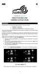
iShutter Manual 1 General Information about Z-Wave Reliable: Generally radio systems build a direct link between the transmitter and the receiver. The radio signal is attenuated by every obstacle along its path (in the household e.g. wall, furniture etc). In the worst case the radio system ceases to function. The advantage of the intelligent Z-Wave system is the so-called routing function: All mains powered devices of Z-Wave not only act as transmitter or receiver but also simultaneously as “repeater”. Should a direct radio link between the transmitter and the receiver not be possible, communication will be established with the assistance of other devices. Communicative: Z-Wave is a bidirectional radio system. This means that a signal is not just sent but also a feedback confirming the reception of the signal occurs automatically. The safety of transmission of the Z-Wave radiobus-technology is comparable with that of a wire-linked bus system. Trouble-free: Z-Wave transmits at a regulated frequency band with a frequency of 908 MHz (US) / 868 MHz (EU). Every ZWave network has its own unique network identification. Therefore, it is possible to operate two or more independently operating networks in a room or home without any interference. Troubles that can be caused by other devices, as is the case in open, non-regulated frequencies (e.g. 433 MHz) are excluded. Interoperable: Z-Wave is an international standard that ensures that products from different vendors work together seamlessly. The iShutter was certified by the Z-Wave Alliance to guarantee this interoperability. 2 Before Installation/Setup Please read carefully the enclosed user manual before installation of the radio-actuator, in order to ensure an error-free functioning. ATTENTION: only authorized technicians under consideration of the country-specific installation guidelines/norms may do works with 230 Volt networks. Prior to the assembly of the product, the voltage network has to be switched off and ensured against re-switching. The product is permitted only for proper use as specified in the user manual. Any kind of guarantee claim has to be forfeited if changes, modifications or painting are undertaken. The product must be checked for 1 damages immediately after unpacking. In the case of damages, the product must not be operated in any case. If a danger-free operation of the equipment cannot be assured, the voltage supply has to be immediately interrupted and the equipment has to be protected from unintended operation. 3 Installation The iShutter can be controlled both by using external analog switches, as well as wireless wall switch or remote control. The assembly must take place in a voltage-free state by an authorized electrical technician. Turn off the power supply prior to the mounting and confirm the absence of voltage with a 2-pin voltage checker. Protect your installation from re-switching. An assembly in built-in sockets is possible. As a result of the compact design, the iShutter is supposed to we either installed as a separate product in a wall box or behind a traditional wall switch. 4 Wireless Functions – Z-Wave 4.1 Z-Wave Network Inclusion In order to use the device by a controller the device needs to be included into a Z-Wave network. Only device that are part of the same network can send commands to the device. 1. Follow the instructions on your Z-Wave Primary or Inclusion Controller to include (add) a Z-Wave device 2. Triple press Up or Down button. 3. The LED going on for 2 secs indicates success. Failure is indicated by 8 blinks. 4. Your device is ready to work! 4.2 Z-Wave Network Exclusion ´ In order to remove the device from a Z-Wave network the following steps have to be performed. 1. Follow the instructions on your Z-Wave Primary or Inclusion Controller to exclude (remove) a ZWave device 2. Triple press Up or Down button. 3. The LED going on for 2 secs indicates success. Failure is indicated by 8 blinks. 4. Note! All configurations and associations stored in the device are deleted during Exclusion process 5. Your device can now be removed physically! Attention: Removing the device from the network means that it is turned back into factory default status. 4.3 Z-Wave Associations The iShutter supports two association groups. Refer to your Z-Wave Controller instructions to add devices in these association groups. A PC gateway/controller gives you the most comfortable and powerful way to configure your device. Association groups: 1. Click or hold down/up button controls devices in Association group No 1 2. Reports on Shutter state change will reported to devices in group No 2 All groups support up to 10 nodes and 10 (node, channel) pairs. If the device is associated to a static controller it can be used to activate scenes in this controller. If the configuration parameter #6 is set to the value 2 the following scene activation commands are sent to the target nodes of the association group: Scene 1: On moving Up Scene 2: On stopping Scene 3: On moving Down 3 4.4 Z-Wave Configuration Z-Wave products are supposed to work out of the box after inclusion, however certain configuration can adapt the function better to user needs or unlock further enhanced features. IMPORTANT: Controllers may only allow configuring signed values. In order to set values in the range 128…255 for parameters 4, 10, 11 and 12 the value sent in the application shall be the desired value minus 256. For example: to set parameter 4 in Window Blind to 200 s it may be needed to set a value of 200−256=−56. Similar rule applies to parameter 2: to set values in range 32768…65535 use value equal to desired value minus 65536. For example, to set auto switch off period to 10 hours = 36000 s it may be needed to set a value 36000−65536=−29536. Buttons Mode (parameter No 1, size 1 byte) One push button: One button is used (chose any), press while moving up and down stops, while stopped moves to opposite direction to previous. Two buttons with neutral position: Up click moves up if stopped and stops if moving down, Down click moves down if stopped and stops if moving up, Hold Up/Down moves in up/down, Release stops. Two toggle switch: Switch to Up/Down moves up/down. Two paddles with Power and Direction: Hold Up button to move blinds up. If Down button is pressed, blinds will move down. Release Up button to stop. Two paddles with Power and Direction toggle: Hold Up button to move blinds up. Down button toggle between up and down motion. Values: 0 One push button (default) 1 Two paddles with Power and Direction 2 Two toggle switch 3 Two buttons with neutral position 4 Two paddles with Power and Direction toggle Automatically close after (parameter No 2, size 2 bytes) If not zero, automatically switch off / close blind after a user defined time Values: 0 Disabled (default) 1 – 65535 Close after this time (in s) What to do on RF off command (parameter No 3, size 1 byte) Defines how to interpret RF Off command. Can be used in conjunction with Auto Close function: Ignore - to open the door by motion detectors and close it back after some amount of time: in case of multiple motion detectors each would try to open that would break logics; Open - to open on both On and Off paddle press on the remote and close after some amount of time. Button close click will still work (if button operations are not disabled). Note that Dim Down command will still begin close motion. Values: 0 Switch off (default) 1 Ignore 2 Switch on 3 Open if close, otherwise close Typical click timeout (parameter No 4, size 1 byte) Typical time used to differentiate click, hold, double and triple clicks Values: 1 – 100 in 10 ms units (default is 50, that is equivalent to 500 ms) Invert buttons (parameter No 5, size 1 byte) Values: 0 No (default) 1 Yes Action on button press or hold (parameter No 6, size 1 byte) 5 Defines which command should be sent to Association group on button press or hold. Scene mode will send 1 for Up event, 2 for Stop, 3 for Down. Values: 1 Switch On, Off and dim using Multilevel start/stop (default) 2 Send Scene LED mode (parameter No 7, size 1 byte) Set LED indication mode Values: 0 Disabled 1 Show working state (default) 2 always on 3 show opened state 4 Indicator Command Class Full close time (parameter No 10, size 1 byte) Time to go from opened to closed state. Used to estimate the current level. Note that in permanent motion mode the reported value would be closed or opened, while all Basic and Multilevel Set values (1…99, 255) would open except 0 value that would close. Values: 0 keep in permanent motion 1 – 255 in s (default is 60 s) Full open time (parameter No 11, size 1 byte) Time to go from closed to opened state. Used to estimate the current level. Note that in permanent motion mode the reported value would be closed or opened, while all Basic and Multilevel Set values (1…99, 255) would open except 0 value that would close. Values: 0 keep in permanent motion 1 – 255 in s (default is 60 s) Node Id of the blocking device (parameter No 12, size 1 byte) Id of the blocking device. Commands from this device would be interpreted not as Open/Close, but as block/unblock. Useful with door opening detector: if the door is open, block the blind not to break shades while they move. Values: 0 disabled (default) 1 – 232 Node Id of the blocking device On which command from blocking node to enable the protection (parameter No 13, size 1 byte) Defines which command from blocking device to interpret as closed door and hence, unprotected. Values: 0 on “On” (default) 1 on “Off” Invert Open and Close relays (parameter No 14, size 1 byte) Allow exchanging open and close relays if blind control is wired to the motor incorrectly Values: 0 No (default) 1 Yes Reset to factory Default (parameter No 254, size 1 byte) Attention: This will delete all your configuration, but the device will remain in the network. Handle with care. 7 Values: 254 Execute reset 4.5 Child Protection The device can be turn into a child protection mode. This means that the local operation of the device is not possible. The child protection mode MUST be turned on wirelessly. However it is possible to unlock the device for local operation with a triple click. The unlock state will last for 5 seconds. 4.6 Z-Wave Specific Device Information 4.6.1 Z-Wave Device Types Generic: Multilevel Switch Specific: Motor Control Class C 4.6.2 Supported Command Classes: All Switch (V1) Association (V2) Basic (V1) Binary Switch (V1) Configuration (V1) Indicator (V1) Manufacturer Specific (V1) Multi Channel Association (V2) Multilevel Switch (V3) Node Naming and Location (V1) Protection (V1) Version (V1) Scene Activation (V1) SceneActuatorConf (V1) 4.6.3 Controlled Command Classes Multi Channel Multilevel Switch Scene Activation 5 Electrical circuit: 6 LED Modes OK - 2 seconds Failed - 8 blinks Not in Network - Permanent blinks 7 Technical data 9 Receiving frequency: 868.42 MHz Switching capacity: resistive 1 800 W, Operating voltage: 230 V, 50 Hz Dimensions (H x W x D): 51 x 46 x 31 mm Operating temperature: 0°C to +40°C