1
ZCSS1
EN
in association with
™
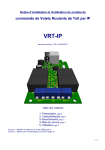
Z-WAVE® CORD SWITCH SET
Installation and User's Guide
FOREWORD
The basic Swiid® Cord Switch Set (called SwiidPack™ for short) contains :
1 SwiidInter™ cord switch
1 SwiidPlug™ adapter plug
1 wireless wall controller switch (a Z-Wave>Me™ product)
The pack provides a READY-TO-USE solution to automate the lighting in a room without having
to redo any of the wiring …
Typically in a bedroom, this enables you to operate your bedside lamp from the door and at
the same time to turn on and off other lights in the room from your bedside without having to
get out of bed !
What's more the installation and setup are incredibly easy, as we have already configured the
system for you in our factory. So, ALL YOU NEED IS TO :
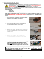
1. Replace the existing cord switch on your bedside lamp by the SwiidInter™ cord switch
(see Page 5),
2. Stick or screw the wall controller switch where you want (near the door ?) after having
activated the batteries (see Page 10), and
3. Fit the SwiidPlug™ adapter plug on another lamp in the room which you want to control
from your bedside (see Page 17).
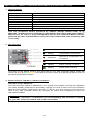
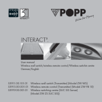
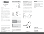
Et voilà ! It works RIGHT OUT OF THE BOX in the way shown on the following diagram.
IT'S THAT SIMPLE !!!
P.S. Just make sure the "adapter plug" lamp does not itself have one of those "good old" cord switches !!!
-1-
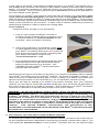
Up to now we have described way in which the devices of your SwiidPack™ have been preset in our factory. This being said, they are all fully certified Z-Wave® devices and can therefore
easily be incorporated into - or serve as the nucleus for - a more comprehensive Z-Wave®
home automation system which you can control locally or from a remote smartphone, tablet or
computer anywhere in the world. All the devices in your SwiidPack™ are Z-Wave® certified,
which means that they are fully interoperable with Z-Wave® devices from other manufacturers,
provided the latter are Z-Wave® certified as well and work on the same authorised radio
frequency (EU in our case).
The SwiidInter™ cord switch contained in the pack can be reprogrammed to activate by way
of a long press a complex home automation scenario through a static primary controller : for
example, turn off all the lights in the house, bolt-lock the front door, close the shutters and
finally activate the downstairs alarm.
The wall controller switch provided in your SwiidPack™ (a Z-Wave>Me™ product from Z-Wave
Europe GmbH) is a fully-fledged Z-Wave® primary controller and can therefore be used to
include other Z-Wave devices in its network or to exclude devices contained in your pack.
If you already have a Z-Wave® network, you can include the set's wall controller switch into
that network, whereby it will then be a "secondary" controller. In doing so, the factory-set
associations between the devices contained in your SwiidPack™ will obviously be destroyed
and they will have to be reprogrammed, if you want to them to function again.
-2-
TABLE OF CONTENTS
The Installation and User's Guide of this Swiid® Cord Switch Set has a separate section for
each of the three devices it contains namely :
1. The Swiid® cord switch,
2. The wall controller switch (a Z-Wave>Me™ product), and
3. The Swiid® adapter plug
NOTE : If you intend to use your Swiid® Cord Switch Set without changing its setup, all you
need to know is contained in the Chapters 3 and 4 of Sections I-III.
SECTION I – SWiiD® CORD SWITCH
1.
Specifications ............................................................................................................. 4
2.
Key features .............................................................................................................. 4
3.
Installation of the cord switch ..................................................................................... 5
4.
Operating the cord switch .......................................................................................... 6
5.
Inclusion of the cord switch into a Z-Wave® network .................................................. 6
6.
Exclusion of the cord switch from a Z-Wave® network ................................................ 7
7.
Cord switch associations ........................................................................................... 8
8.
Resetting the cord switch ........................................................................................... 9
9.
Advanced settings ..................................................................................................... 9
SECTION II – WALL CONTROLLER SWITCH (a Z-Wave>Me™ product)
1.
Specifications .............................................................................................................10
2.
Key features ..............................................................................................................10
3.
Installation of the wall controller switch ......................................................................10
4.
Operating the wall controller switch ............................................................................11
5.
Primary or secondary Z-Wave® controller ? ................................................................11
6.
The wall controller switch as a primary Z-Wave® controller ........................................12
7.
8.
The wall controller switch as a secondary Z-Wave® controller ....................................14
Wall controller switch associations .............................................................................15
9.
Resetting the wall controller switch ............................................................................16
10. Advanced settings .....................................................................................................16
SECTION III – SWiiD® ADAPTER PLUG
1.
Specifications .............................................................................................................18
2.
Key features ..............................................................................................................18
3.
Installation of the adapter plug ...................................................................................18
4.
Operating the adapter plug ........................................................................................18
5.
6.
Inclusion of the adapter plug into a Z-Wave® network ................................................19
Exclusion of the adapter plug from a Z-Wave® network ..............................................20
7.
Adapter plug associations ..........................................................................................20
8.
Resetting the adapter plug .........................................................................................20
SECTION IV – GENERAL
1.
What is Z-Wave® ? .....................................................................................................21
2.
Warranty ....................................................................................................................21
3.
Swiid® / CBCC Domotique SAS .................................................................................22
-3-
SECTION I - SWiiD® CORD SWITCH
1. SPECIFICATIONS
Device Type :
Power input :
Max. power :
EU Norms :
Protection index :
Size :
Radio protocol :
Radio frequency :
Transmission distance :
Working temperature :
ON/OFF signal :
Power consumption :
EU patent
BINARY POWER SWITCH
230V ± 10% - 50Hz
660W
EN 61058-2-1:2011 & EN 55015
IP20
84 x 32 x 29 mm
Z-Wave® (SDK 4.55)
868,42 MHz (EU)
Max. 30m indoors depending on construction materials
0 – 40°C
Blue LEDs
< 0,08W
Pending
Your Swiid® cord switch has been certified by a certification firm approved by the
Z-Wave® Alliance and, as such, is fully interoperable with all the certified Z-Wave®
devices produced by other manufacturers using the same authorised radio
frequency (EU in our case).
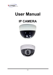
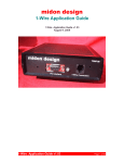
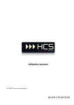
2. KEY FEATURES
Top outside
Bottom outside
1.
1. Z-Wave® pairing
guide (blinking red
LED during
inclusion/exclusion
and association)
2. Assembly screw
ON/OFF
button
(blue LEDs are lit
when "On")
Remember to disconnect from the power mains before opening the
switch
Top inside view
Bottom inside
view
1. Front AC wire
terminal towards
the device (lamp)
2. ON/OFF switch
3. Blue LED "On"
indicator
4. Back AC wire
terminal towards
the mains (socket)
1. Z-Wave®
inclusion/exclusion
and association
button (linked to the
pairing guide)
2. Red LED: inclusion/
exclusion,
association and
reset indicator
3. Fuse (fixed)
-4-
3. INSTALLATION OF THE CORD SWITCH
The first step in the installation of your Swiid® cord switch is the same as for
any cord switch, so first and foremost remember to disconnect from the
power mains the device on which you install the Swiid® cord switch.
Before starting, you must determine the exact location of the switch on the cord to be
able to operate the switch comfortably.
Tools required:
- Wire cutter
- Wire stripper
- Electrician's flat and Phillips screwdrivers
After making sure that the power cord on which you want to install your Swiid® cord
switch is disconnected from the power mains, carefully follow the steps described
below
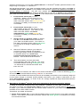
1. Using the Phillips screwdriver, remove the upper
shell cover of your Swiid® cord switch
2. Using the wire cutter, cut the cord where you
want to install your Swiid® cord switch
3. With the wire cutter, separate the two inner wires
and remove 6 mm of the outer insulation sheath
on both ends
4. With the wire stripper, strip 3-4 mm of the
insulation of the two inner wires on both ends
5. Using the flat screwdriver, connect the wires by
screwing them into two terminals inside the Swiid®
cord switch respecting the directions of the
wires: front towards the device (lamp – near the
bulb marking) and back towards the mains (socket
– near the "L" "N" marking)
WARNING: If you reverse the mounting direction of the wires, your Swiid® cord
switch will not work at all. This will not damage your Swiid® cord switch, but
you will need to reinstall the wires all over again always taking care to
disconnect the electrical power cord.
-5-
6. Using the Phillips screwdriver, tighten the security
clamps over the power cord, making sure they
pinch the cord's outer insulation sheath firmly, so
that it is held securely
7. Replace the upper shell cover of the switch and
tighten with the Phillips screwdriver the assembly
screw which joins the two shell covers of the
switch
WARNING: Make sure you do not cut or shorten the wire antenna attached to the
bottom of PCB, as its length is optimized for the radio frequency used by your
Swiid® cord switch.
8. Connect the plug of the power cord to the mains,
and then check that the Swiid® cord switch works
normally by pressing on the ON/OFF button.
When on the "ON" position, the blue LEDs should
illuminate the button and the lamp should switch
on
WARNING: The presence near your Swiid® cord switch of grounded metallic
objects or of high power conductors can affect the Z-Wave® radio signals and
thus the remote controlling of your Swiid® cord switch.
If your Swiid® cord switch is intended to replace a pre-existing cord switch, you must
first disassemble and remove the latter from the power cord (as always, only when the
power has been disconnected from the mains). Then you will need to adapt the ends
of the cord which will be fitted into your Swiid® cord switch so as to conform to what
was described in Steps 3 and 4 above. Apart from that, follow all the exact same steps
as described above.
4. OPERATING THE CORD SWITCH
Your Swiid® cord switch is operated by either a short press or a long press (> 0.5 seconds)
on the ON/OFF button. When your Swiid® cord switch is on, the blue LED's will light up
through the transparent rim ("") of the ON/OFF button.
A short press on the ON/OFF button will always toggle on or off the lamp on the cord on
which your Swiid® cord switch is attached.
If you intend to use your Swiid® Cord Switch Set without changing its configuration, then
a long press on the ON/OFF button will toggle both the lamp of the cord switch and the
Swiid® adapter plug.
More generally, the ON/OFF button a Swiid® cord switch functions as follows in operating
mode:
Short press toggles on or off the lamp and sends a signal to the Group 2
associated devices (see Chapter 7)
Long press toggle on or off the lamp and sends a signal to the Group 1 associated
devices
5. INCLUSION OF THE CORD SWITCH INTO A Z-WAVE® NETWORK
In order to control your Swiid® cord switch remotely, it needs to be recognized by a
Z-Wave® network. Many people are put off by the very use of the word "network", but it
may in fact designate a single remote control or wireless switch coupled with a plug or a
lamp. The important thing to remember is that your Swiid® cord switch needs to be
recognized by any device which is intended to control it (you can't call your dog, if you
don't know its name). To do this, an inclusion operation needs to be performed: this is
also often called an integration or a pairing operation.
-6-
In the case of the Swiid® cord switch provided as part of your Swiid® Cord Switch Set, it
has already been included in the factory in the Z-Wave® network of the set's wall controller
switch. It is therefore necessary to clear the memory of cord switch to include in another
Z-Wave® network. This is done by performing an exclusion procedure as described in
the next Chapter of this Section.
The inclusion of a Swiid® cord switch is performed with the switch fully assembled (shell
cover joined and screwed together) and with the power cord plugged into the mains.
When including a Swiid® cord switch, make sure that it is in its final position. If this location
is not in the direct range of the including controller then the Cord Switch has to be moved
closer to the controller for the Inclusion ; in which case a network rediscovery process is
subsequently needed in order to refresh the routing table.
Tools required:
- Fingernail (if thin enough) or any pointed tip
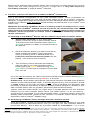
1. First put your primary Z-Wave® controller in
inclusion mode (generally done by pressing once
or several times on an inclusion button on the
controller : here an Aeotech Z-Stick2)
2. Using your fingernail or a pointed tip, press once
on the Z-Wave® pairing guide on the bottom of
your Swiid® cord switch after which a red LED will
light up through the pairing guide, indicating that
your Swiid® cord switch is now in the
"inclusion/exclusion" mode
3. The inclusion/exclusion process should then start
automatically and the red LED will blink before
staying lit permanently for 2 seconds. This
indicates that the Z-Wave® inclusion/exclusion
process was successful
Depending on the type of controller you are using, you may be immediately able to operate
your Swiid® cord switch via your Z-Wave® network. For some controllers, however, you
need to perform an additional pairing step in order to assign your Swiid® cord switch to a
specific command button on the controller (e.g. on a multi-button remote control)
Once you are able to operate your Swiid® cord switch remotely from your Z-Wave®
network, you are able to check that the blue LEDs light up to illuminate the perimeter of
the ON/OFF button when it is turned on remotely. Also check that your Swiid® cord switch
continues to respond to a manual press locally on the ON/OFF button.
WARNING : As with any Z-Wave® "binary switch" device, the Swiid® cord switch is
not able - for patent reasons - to report back its status changes automatically to a
Z -Wave® controller. The best way to monitor the change in status of your Swiid®
cord switch in real-time is to associate it via the second association group (see
Chapter 7 on "Cord switch associations") with your primary controller. This works
both when the change in status of your Swiid® cord switch is the result of a manual
action and when it is linked to a command communicated through the Z-Wave®
network.
FOR CERTAIN Z-WAVE® CONTROLLERS, THIS ASSOCIATION IS PREPROGRAMED TO BE IMPLEMENTED ON ITS OWN WHEN YOUR SWIID® CORD SWITCH IS FIRST
INCLUDED INTO THE NETWORK.
6. EXCLUSION OF THE CORD SWITCH FROM A Z-WAVE® NETWORK
To exclude your Swiid® cord switch from a Z-Wave® network, proceed in the same way as
for the integration/inclusion described in the previous Chapter, except that in Step 1, you
must press the exclusion button on the Z-Wave® controller that you will have brought
-7-
into the vicinity of your Swiid® cord switch (or vice versa). The red LED on the bottom of
your Swiid® cord switch will behave in the exact same way as during the inclusion process.
7. CORD SWITCH ASSOCIATIONS
“Associations” can be set up between your Swiid® cord switch and other devices in the ZWave® network in which they operate. In Z-Wave® speak, an "association " means that
one node (i.e. device) is programmed to control directly another node whenever the status
of the first of these two nodes changes (by being triggered or operated) and this without
needing to pass through any Z-Wave® controller.
A typical example would be an association between a Z-Wave® door sensor with a ZWave® light switch, so that when the door sensor is triggered the light switch is
automatically turned on, even if no Z-Wave® controller is active at the time.
Associations are obviously only possible between devices which are part of the same ZWave® network.
Associations are unidirectional (one-way) from a first node (the “primary”, "controlling" or
"source" node or device) which issues a message to the second node (the “secondary”,
"controlled" or "target" node or device) which receives the message and executes a
corresponding pre-agreed action. It is possible to have bi-directional (reciprocal)
associations between two devices A and B, but in order to achieve this, it is necessary to
create two separate associations : one from A to B and a second one from B to A.
A primary node can be associated with more than one secondary nodes, the maximum
number of which depends on the characteristics of the primary node device. This is known
as a "group" association. Conversely, a secondary node can receive and execute
commands from any number of primary nodes with which it has been associated.
Your Swiid® cord switch is capable of handling two association groups:
The first association group (Group 1) will respond to a long press (over 0.5
seconds) on the ON/OFF button of your Swiid® cord switch
The second association group (Group 2) works on every press (actually on every
release) on the ON/OFF button of your Swiid® cord switch (this is the one which can
be used to notify status changes)
In each of the two association groups, your Swiid® cord switch can be combined with up
to 5 normal Z-Wave® devices.
The process for associating your Swiid® cord switch with other Z-Wave® devices can be
made either via a Z-Wave® controller or - in the case where the cord switch will be the
"controlling" device - by direct association with the other Z-Wave® device.
Association via a Z-Wave® controller
To associate your Swiid® cord switch with another Z-Wave® device of the same Z-Wave®
network via the network's controller, please revert to and follow the association instructions
set out by the controller's manufacturer. Normally, this should not require your having to
do anything on your SwiidInter™ cord switch.
Direct association
To simplify association procedures, your Swiid® cord switch can create associations with
other Z-Wave® devices directly without having to go through a controller. Such "direct"
associations are, however, subject to three constraints:
All the devices must already be part of the same Z-Wave® network (i.e. have been
included in the Z-Wave® network directly or indirectly by the same primary controller)
These associations can only be made with the first association group (Group 1) of
your Swiid® cord switch
These associations are unidirectional : from your Swiid® cord switch to another ZWave® device which it will control and not the other way around
To create such "direct" associations, proceed as follows:
1. Press with your fingernail or a pointed tip on the Z-Wave® pairing guide on the bottom
of your Swiid® cord switch (plugged into the mains) and keep pressed for 1-2
-8-
seconds until the red LED lights up permanently through the pairing guide. This
indicates that your Swiid® cord switch is now in the "association" mode.
2. Place the Z-Wave® device to be associated in the immediate vicinity and put it in the
"inclusion/exclusion" mode in the way prescribed by the device's manufacturer
3. If the association is successful, the red LED on the bottom of your switch Swiid® cord
switch will blink twice and then turn off, indicating that your Swiid® cord switch has
gone back to its "normal" operating mode. If the association is not successful, the red
LED will go out after 20 seconds without flashing (back to "normal")
You can only associate in this way one Z-Wave® device at a time and you will need to
repeat the process to add another device Z-Wave® (always only on the Swiid® cord
switch's first association group).
WARNING: Sending relevant association information between devices may take
some time, in certain cases even a full minute.
WARNING: When your Swiid® cord switch is sending a command to one or more
associated devices and receives at the same time an instruction to issue a new
command, the original broadcast is interrupted and the new command is
immediately issued.
8. RESETTING THE CORD SWITCH
To reset your Swiid® cord switch to its factory settings (erasing the Home ID of the
network's primary controller), press with your fingernail or a pointed tip on the Z-Wave®
pairing guide on the bottom of your Swiid® cord switch (plugged into the power mains)
and keep pressed for a long time. The red LED will first turn on for a few seconds
(association mode) and ultimately turn off. Once the red LED turns off, release the pairing
guide, the red LED will then blink twice rapidly and once longer, indicating that your
Swiid® cord switch has been fully reset.
9. ADVANCED SETTINGS
Your Swiid® cord switch offers a limited range of advanced configuration options,
essentially turning on and off the Switch All functionality. Changing these configuration
options requires the use of one or other of the more sophisticated Z-Wave® controllers
(usually Z-Wave® IP gateways). For a description of these configuration options, please
refer to our website at :
www.swiid.com/en/support/documentation-swiidinter.html
-9-
SECTION II – WALL CONTROLLER SWITCH (a Z-Wave>Me™ product)
1. SPECIFICATIONS
Device Type :
Power supply :
Size :
EU Norms :
Radio protocol :
Radio frequency :
Transmission distance :
Working temperature :
LED :
REMOTE CONTROLLER
2x AAAA mini, 1.5V (LR8D425)
71 x 71 x 22 mm
EN 61058-1 & EN 55015
Z-Wave®
868,42 MHz (EU)
Up to 30m indoors (depending on construction materials)
0 – 40°C
Red/Green/Yellow 3-colour LED (inner front face)
This wall controlled switch produced by Z-Wave Europe GmbH under its ZWave>Me™ brand has been certified by a certification firm approved by the Z-Wave®
Alliance and, as such, is fully interoperable with all the certified Z-Wave® devices
produced by other manufacturers using the same authorised radio frequency (EU
in our case).
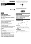
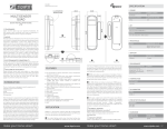
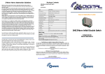
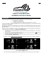
2. KEY FEATURES
Red/Green/Yellow
LED indicator
permanent
Configuration successful
blinking
Configuration mode active
permanent
ERROR : Device/group
defective or configuration not
successful
3x blink
Weak battery
blinking
Switch controls no device
blinking
Switch reset underway
As shown on the above picture, the inner face of your wall controller switch under the
rocker has a red/green/yellow LED and its various colour and blinking patterns when lit
provide the indications shown.
3. INSTALLATION OF THE WALL CONTROLLER SWITCH
Activation of the batteries:
The wall controller switch is delivered in your Swiid® Cord Switch Set with two batteries
(2x AAAA) already positioned in the battery casings, but one of them has a red insulation
tape at one end which needs to be removed. To do so, you may need to access the inner
face of your wall controller switch by unhinging its rocker and unclipping its frame as
described hereafter.
WARNING: If you need to change the batteries, make sure you insert them in the
correct (+)/(-) direction, as otherwise you could damage the electronic circuitry
of your wall controller switch and render it unusable.
- 10 -
Accessing the inner face of your wall controller switch:
To access the inner face of your wall controller switch,
insert a small flat screwdriver in one of the corners
between the rocker and frame, force sideway outwards
and up to lift away the rocker, as shown.
Mounting of your wall controller switch:
Thanks to its extremely flat design, the wall controller switch does not require any
substructure (e.g. pattress box) and can be mounted directly on a variety of different flat
wall surfaces.
To mount your wall controller switch, you can :
Stick it onto smooth surfaces such as glass or tiles using the pieces of two-faced
adhesives strips provided,
Screw it onto a wall or an existing pattress box, or
Clip it into a compatible existing multiple wall switch frame (Busch-Jaeger)
Both the second and third alternative require you first to unhinge the rocker and unclip the
frame of your wall controller switch as described previously.
In all cases, make sure that the arrow marked TOP on the inner face of your wall controller
switch is pointing upward.
Once fixed to the wall, clip first the frame and then the rocker back onto your wall controller
switch.
4. OPERATING THE WALL CONTROLLER SWITCH
If you intend to use your Swiid® Cord Switch Set without changing the setup of the devices
(or adding new devices), then :
a single press UP on the paddle will turn "ON" only the lamp attached to the Swiid®
Cord Switch and a single press DOWN on the paddle will turn it OFF
a double press UP on the paddle will turn "ON" BOTH the lamp attached to the
Swiid® Cord Switch and the one attached to the Swiid® Adapter Plug. Conversely,
a double press DOWN on the paddle button will turn them both "OFF".
If you use the wall controller switch in a different set up (but without changing its advanced
parameters), then :
Single press UP or DOWN on the paddle (and release) will turn the first controlled
device/group "ON" or "OFF"
Double press UP or DOWN on the paddle (and release) will turn the second
controlled device/group "ON" or "OFF"
Single press UP or DOWN on the paddle and hold will dim UP or DOWN the first
controlled device/group
Double press UP or DOWN on the paddle and hold will dim UP or DOWN the second
controlled device/group
5. PRIMARY OR SECONDARY Z-WAVE® CONTROLLER ?
As configured in your Swiid® Cord Switch Set, your wall controller switch is the primary
controller of the other devices contained in the set.
Your wall controller switch is a full-fledged certified Z-Wave® primary remote controller,
but it can also be used as a secondary controller.
As a primary controller, it creates its own network using its factory-set unique identification
number (known as Home ID), which will be attributed to all the devices (including additional
controllers) which will be included into its Z-Wave® network.
- 11 -
Because this wireless wall controller switch can control only a limited number of devices/
groups and was really designed to be used in a single room, it very often used as a
secondary controller in wider Z-Wave® networks.
6. THE WALL CONTROLLER SWITCH AS A PRIMARY Z-WAVE® CONTROLLER
This is the default configuration of your wall controller switch. There is therefore no
specific set up necessary for your wall controller switch to act as a primary controller.
However, configuration steps are necessary for each additional device which you want to
include in its network (over and above those already included as part of your Swiid® Cord
Switch Set).
REMINDER: Controlling a Z-Wave® device is in theory ALWAYS a 2-step process 1: FIRST
inclusion into a Z-Wave® network so that the device can communicate with all the
other devices and controllers of that network and SECOND defining which switch (or
switches, switch sequences or remote control buttons) will effectively control the
device concerned.
A- Including a new Z-Wave® device into the network of the wall controller switch
1.
Press three times (3x) on the "INCLUDE"
button on the front of your wall controller switch.
The LED on the wall controller switch will blink
green to indicate it is ready to include devices in
its network
2.
Get the Z-Wave® device you want to include to
issue a Node Information Frame (generally
done by pressing once or several times on a
FUNCTION (inclusion/exclusion) button on the
device – see manual of the device)
3.
The inclusion process will start automatically
with the LED on your wall controller switch
briefly lighting up yellow before turning solid
green for a 1-2 seconds to indicate success and
then turn off
If you are not successful, the LED on the wall controller switch continue blinking green
for around 5 seconds before turning red for 1-2 seconds.
PLEASE NOTE : at this stage, although the new device has been included in the Z-Wave®
network of your wall controller switch, it will NOT respond to any form of press on the UP
or DOWN buttons of the wall controller switch. This is because the allocation step
necessary to link the new device to specific paddle presses (simple vs. double) of your
wall controller switch has not yet been performed (see Section B below).
Indeed, there are cases where you might want to include devices into the Z-Wave®
network of your wall controller switch which you either cannot - or do not want to control through the paddle of your wall controller switch. A typical example, which has
already been mentioned, would be the inclusion a Z-Wave® motion sensor (say to
associate it with a Z-Wave® adapter plug).
B- Controlling a Z-Wave® device through the wall controller switch
Once the Z-Wave® device concerned has been included into the network of your wall
controller switch as described above, then you can get your wall controller switch to
control this device. This is done by a process called an "association". For a more
1
There are however certain controllers that are programmed so that the 2 steps are combined into what seems like a one-step
process of creating both the communication and the control allocation. The drawback is that this is ONLY valid for Z-Wave®
devices which do not have a network "Home ID" either because they come straight from the factory or because their previous
Home ID has been erased through an "Exclusion" procedure (see below).
- 12 -
detailed explanation of what are "associations" in Z-Wave® speak, please revert to the
beginning of Chapter 7 in Section I.
As mentioned earlier, your wall controller switch can be operated by either a single or
a double press UP or DOWN on its paddle and thereby control two different devices or
groups (sets) of devices. So you can create two different associations groups,
depending whether you single click or double click on the UP or DOWN button/paddle of
your wall controller switch during Step 3 of the association process described below :
1.
Press three times (3x) on the
"ASSOC." button on the front of your
wall controller switch. The LED on the
wall controller switch will blink yellow to
indicate it is ready to receive the next
command
2.
Press three times (3x) on the
"INCLUDE" button on the front of your
wall controller switch. The LED on the
wall controller switch will blink
alternatively green and yellow to
indicate it is ready to receive the next
command
3.
Single click (or double click) on either
the UP or the DOWN button the front of
your wall controller switch. The LED on
the wall controller switch will blink green
to indicate it is ready to associate a
device
4.
Get the Z-Wave® device you want to
control to issue a Node Information
Frame (generally done by pressing once
or several times on a FUNCTION
(inclusion/exclusion) button on the
device – see manual of the device
5.
The association process will start
automatically with the LED on your wall
controller switch turning solid green for
1-2 seconds to indicate success and
then turn off
K
If you are not successful, the LED on the wall controller switch continue blinking green
for around 5 seconds before turning red for 1-2 seconds.
In order to have additional devices (which are already included in the network) respond
to the same single or double press paddle command, you need to add them to the
same association group. In order to do so, simply repeat all steps described above
for each additional device.
C- Excluding a Z-Wave® device from the network of the wall controller switch
In order to exclude a device from the Z-Wave® network of your wall controller switch,
the steps to follow are exactly the same as for the inclusion of the device except that
in Step 1 you need to press on the "EXCLUDE" button of your wall controller switch
instead of the "INCLUDE" button.
Therefore, proceed as follows:
1. Press three times (3x) on the "EXCLUDE" button on the front of your wall controller
switch. The LED on the wall controller switch will blink green to indicate it is ready
to exclude devices.
- 13 -
2. Get the Z-Wave® device you want to exclude to issue a Node Information Frame
(generally done by pressing once or several times on a FUNCTION
(inclusion/exclusion) button on the device – see manual of the device.
3. The LED on the front of your wall controller switch will light solid green for 1-2
seconds before turning off, indicating that the device has been successfully excluded
and that the Home ID of the remote controller erased from the device.
The device from which Home ID of your wall controller switch will have been erased
will thus be ready to be included into another Z-Wave® network. Of course this means
that it can no longer be directly associated with any other device (e.g. switch) which is
part of the network from which it has been excluded : you would first need to re-include
it in the Z-Wave® network.
This deletion action is also recommended before including any device into a Z-Wave
network in order to make sure that it has not inadvertently retained the Home ID of
another network.
D- Removing the control over a Z-Wave® device from the wall controller switch
There may be cases where you will want to stop controlling a device from your wall
controller switch while keeping it in the Z-Wave® network (e.g. to preserve associations
with other devices in the network).
The steps you will need to follow to
unset/remove/delete the specific association are exactly the same as for the setting
up of the control over the device (Section B above) except that in Step 2 you need to
press three times (3x) on the "EXCLUDE" button of your wall controller switch instead
of on the "INCLUDE" button. So proceed as follows :
1. Press three times (3x) on the "ASSOC." button on the front of your wall controller
switch. The LED on the wall controller switch will blink yellow to indicate it is ready
to receive the next command.
2. Press three times (3x) on the "EXCLUDE" button on the front of your wall controller
switch. The LED on the wall controller switch will blink alternatively red and yellow
to indicate it is ready to receive the next command.
3. Single click (or double click) on either the up or the down button the front of your
wall controller switch. The LED on the wall controller switch will blink green to
indicate it is ready to dis-associate devices.
4. Get the Z-Wave® device you no longer want to control to issue a Node Information
Frame (generally done by pressing once or several times on a FUNCTION
(inclusion/exclusion) button on the device – see manual of the device
5. The LED on the front of your wall controller switch will light solid green 1-2 seconds
before turning off, indicating that the device has been successfully excluded from
the association (whereas the Home ID will have been retained).
If you are not successful, the LED on the wall controller switch continue blinking green
for around 5 seconds before turning red for 1-2 seconds.
7. THE WALL CONTROLLER SWITCH AS A SECONDARY Z-WAVE® CONTROLLER
In order to get your wall controller switch to act as a secondary controller, the first task is
to get it included into the network of your primary Z-Wave® controller: this means that it
will need to take on the Home ID of the primary controller instead of its own factory-set
identification.
The factory-set identification of your wall controller switch will however not be lost and can
be reinstated at any time as its Home ID by running "Reset" procedure (see Chapter 9) :
your wall controller switch will then of course be excluded from the network of the primary
controller.
A- Including the wall controller switch into another Z-Wave® network
Proceed as follows:
1. Press and hold the "ASSOC." button on the front of your wall controller switch for
2-3 seconds until it blinks yellow
2. Before the 4th yellow blink, press and hold the "INCLUDE" button of the front of
your wall controller switch until the LED on the wall switch starts blinking green
- 14 -
3. Put the primary Z-Wave® controller in the inclusion mode (see user's manual of
the controller)
4. The LED on the front of your wall controller switch which had been blinking green
will turn off to indicate the operation was successful.
If you are not successful, the LED on the wall controller switch will light up red.
B- Excluding the wall controller switch from a Z-Wave® network
The easiest way of excluding your wall controller switch from the Z-Wave® network of
a primary controller is to reset it to its factory settings as described later in Section 9.
Please remember that by doing this, your wall controller switch will remain in the
memory bank and routing table of your primary controller, which may create delays and
confusion in its Z-Wave® network. It is therefore generally preferable to use the
exclusion process described in the manual of your primary controller to exclude your
(secondary) wall controller switch.
C- Controlling a Z-Wave® device through the wall controller switch
Same process as when the wall controller switch is acting as primary controller : please
refer above to Point B, Chapter 6 of this Section.
D- Excluding a device from the Z-Wave® network
Exclusion is a fairly indiscriminate process, since it simply erase the Home ID of the
device being excluded and resets it to factory settings. Therefore, even when acting
as a secondary controller, your wall controller switch is capable of excluding devices
from whichever Z-Wave® networks it belongs to. The process is therefore the same
when your wall controller switch is a secondary controller as when it is the primary
controller. The procedure for the primary controller case is the one described in Point
C of Section 6 above.
8. WALL CONTROLLER SWITCH ASSOCIATIONS
Your wall controller switch is capable of creating and deleting associations between
devices (other than itself) which are in the same Z-Wave® network, independently of
whether the wall controller switch is the network's primary controller or one of its secondary
controllers.
However, as your wall controller switch cannot provide you a record of the associations
created, its association creation capabilities are really designed as an ancilliary function
to help cope with just a few simple associations when your wall controller switch is the
network's primary controller. It is therefore recommended that, when your wall controller
switch is setup as a secondary controller, associations between other devices be
programmed via the primary controller.
A- Creating associations
1. Press and hold the "ASSOC." button of your wall controller switch for 2-3 seconds
until the LED starts to blink yellow.
2. Single click on the "INCLUDE" button of the wall controller switch and the LED will
start blinking alternatively green and yellow.
3. Get the Z-Wave® device of the secondary node (i.e. target node) you want to
associate to issue a Node Information Frame (generally done by pressing once or
several times on an inclusion/exclusion button on the device – see manual of the
device), the LED on your wall controller switch will blink only green.
4. Get the Z-Wave® device of the primary node (i.e. source node) you want to
associate to issue a Node Information Frame (again, see manual of the device), the
LED on your wall controller switch will remain lit green for 2-3 seconds and then
turn off indicating that the association has been successfully set up.
In order to create a "group association" (association between one primary node and
several secondary nodes), simply repeat the above process with each of the secondary
nodes in the group.
- 15 -
B- Removing a device from a group association
1. Press and hold the "ASSOC." button of your wall controller switch for 2-3 seconds
until the LED starts to blink yellow.
2. Single click on the "EXCLUDE" button of the wall controller switch and the LED
will start blinking alternatively red and yellow.
3. Get the Z-Wave® device of the secondary node (i.e. target node) you want to disassociate to issue a Node Information Frame (generally done by pressing once or
several times on an inclusion/exclusion button on the device – see manual of the
device), the LED on your wall controller switch will blink only green.
4. Get the Z-Wave® device of the primary node (i.e. source node) which was
controlling the secondary node you want to dis-associate to issue a Node
Information Frame (again, see manual of the device), the LED on your wall
controller switch will remain lit green for 2-3 seconds and then turn off indicating
that the association has been successfully set up.
Note : The device which has been excluded from the group association remains in the
Z-Wave® network and can be further associated and remains controlled by the
network's (other) controllers.
WARNING: Sending relevant association information between devices may take
some time, in certain cases even a full minute.
WARNING: When your wall controller switch is sending a command to one or more
associated devices and receives at the same time an instruction to issue a new
command, the original broadcast is interrupted and the new command is
immediately issued.
9. RESETTING THE WALL CONTROLLER SWITCH
In order to reset your wall controller switch to its original factory status and for it to recover
its factory-set identification number as its Home ID, proceed as follows :
1. Press and hold the "EXCLUDE" button of the back for several seconds until the LED
on starts blinking red/yellow/green.
2. Release the "EXCLUDE" button and press 3x on the UP button and the red/yellow/
green blinking of the LED will accelerate.
3. Then press 3x on the DOWN button and the LED will then remain lit green for 1-2
seconds and then turn off indicating that your wall controller switch has been reset.
All associations in which your wall controller switch was acting as a primary node will
obviously be lost. Associations between devices will however remain intact.
10. ADVANCED SETTINGS
Your wall controller switch offers a range of advanced options, including :
Modification of the configuration parameters of your wall controller switch,
Double press of the UP and DOWN buttons (via the paddle) to operate a second
set of devices,
Single and double press of the UP and DOWN buttons (via the paddle) to activate
up to 16 different Z-Wave® scenes (prior modification of a configuration parameter
required),
Activation of the child protection mode,
Resetting the wake-up intervals (your wall controller switch is battery operated) and
broadcasting wake-up notifications,
Issuing a "Node Information Frame", and
Shifting the primary role to another Z-Wave® controller.
The implementation of any of these advanced options requires the use of one or other of
the more sophisticated Z-Wave® controllers (usually Z-Wave® IP gateways). For a detailed
- 16 -
description of these advanced settings and how to activate them, please refer to the
website of Z-Wave Europe at :
http://manuals.zwaveeurope.com/make.php?lang=en&type=&sku=ZME_05460&pdf=1
- 17 -
SECTION III - SWIID® ADAPTER PLUG
1. SPECIFICATIONS
Device Type :
Power input :
Max. power :
EU Norms :
Protection index :
Size :
Radio protocol :
Radio frequency :
Transmission distance :
Working temperature :
ON/OFF signal :
Power consumption :
BINARY POWER SWITCH
230V ± 10% - 50Hz
3600W
EN300220, EN301489-1/-3 & EN60669-1 + EN60669-2-1
IP20
60.0 x 49.0 x 60.5 mm
Z-Wave® (SDK 4.55)
868,42 MHz (EU)
Max. 30m indoors depending on construction materials
0 – 40°C
blue/yellow LED on FUNCTION button
< 1.5W
Your Swiid® adapter plug has been certified by a certification firm approved by the
Z-Wave® Alliance and, as such, is fully interoperable with all the certified Z-Wave®
devices produced by other manufacturers using the same authorised radio
frequency (EU in our case).
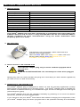
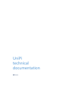
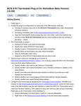
2. KEY FEATURES
Translucent FUNCTION button, which also acts as a
manual on/off toggle switch.
LED is lit blue when "On" and yellow when "Off" and
blinking alternatively blue and yellow when not
included in a Z-Wave® network.
3. INSTALLATION OF THE ADAPTER PLUG
Insert Swiid® adapter plug only in mains sockets equipped with a
ground wire
RISK OF ELECTROCUTION : Do not attempt to clean when plugged
in
Simply plug into the mains socket and plug into it the lamp (or other electric appliance)
you wish to turn on and off remotely.
4. OPERATION OF THE ADAPTER PLUG
The Swiid® adapter plug is designed to switch on and off remotely appliances (mainly
lights) which are plugged into its female socket, The Swiid® adapter plug is suitable for
the wireless Z-Wave® switching of incandescent light as well as halogen and LED lights
(all transformer types).
The Swiid® adapter plug can be operated manually by pressing on its FUNCTION button
which then acts as an on/off toggle switch.
If you intend to use your Swiid® Cord Switch Set without changing its configuration, then
your Swiid® adapter plug has been programmed to be operated remotely and wirelessly
- 18 -
by Z -Wave® (i.e. turned on and off) jointly with the device connected to the set's Swiid®
cord switch by way of :
LONG press on the ON/OFF button of the pack's Swiid® cord switch (assuming the
latter has been mounted on a power supply cable and the cable is plugged in)
DOUBLE press on the UP ("ON") or DOWN button ("OFF") of the pack's wall
controller switch (assuming its batteries are activated and functioning)
5. INCLUSION OF THE ADAPTER PLUG INTO A Z-WAVE® NETWORK
In order to control your Swiid® adapter plug remotely from a different controller, it needs
to be recognized by that controller's Z-Wave® network. Many people are put off by the
very use of the word "network", but it may in fact designate a single remote control or
wireless switch coupled with a single adapter plug. The important thing to remember is
that your Swiid® adapter plug needs to be recognized by any device by which you intend
to control it (you can't call your dog, if you don't know its name). To do this, an inclusion
operation needs to be performed: this is also often called integration or a pairing
operation.
NOTE : If your Swiid® adapter plug came straight from a Swiid® Cord Switch Set, it is
already integrated into the network of the set's wall controller switch (LED lit blue
or yellow permanently) and will need to be excluded before it can be included into
the network of another Z-Wave® primary controller (see Chapter 6 of this Section).
Once cleansed of any pre-existing Home ID (LED blinking alternatively blue and yellow,
the Swiid® adapter plug is ready to be included into the network of any Z-Wave® primary
controller. This is performed with the plug plugged into the active mains and does not
require the use of any tools. Bring your Swiid® adapter plug (always plugged into the
mains) close to the Z-Wave® controller (or vice versa) and proceed as follows :
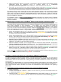
1. First put your primary Z-Wave® controller in
inclusion mode (generally done by pressing once
or several times on an inclusion button on the
controller : here an Aeotech Z-Stick2)
2. With the LED flashing alternatively blue and
yellow, press the FUNCTION button of your Swiid®
adapter plug 3 times (3x) within 2 seconds.
3. The inclusion/exclusion process should then start automatically and the LED will
remain lit blue or yellow based on switch status. This indicates that the Z-Wave®
inclusion/exclusion process was successful.
Depending on the type of controller you are using, you may be immediately able to operate
your Swiid® adapter plug via your Z-Wave® network. For some controllers, however, you
need to perform an additional pairing step in order to assign your Swiid® adapter plug to a
specific command button on the controller (e.g. on a multi-button remote control).
Once you are able to operate your Swiid® adapter plug remotely from your Z-Wave®
network, you are able to check that the blue LED lights up to illuminate the FUNCTION
button when it is turned "ON" (yellow when "OFF"). You can also check that your Swiid®
adapter plug continues to respond to a manual press locally on the FUNCTION button.
- 19 -
WARNING : As with any Z-Wave® "binary switch" device, the Swiid® adapter plug is
not able - for patent reasons - to report back its status changes automatically to a
Z -Wave® controller. The best way to monitor the change in status of your Swiid®
adapter plug in real-time is to use the "association" procedure to associate it with
your primary controller. This works both when the change in status of your Swiid®
adapter plug is the result of a manual action and when it is linked to a command
communicated through the Z-Wave® network.
FOR CERTAIN Z-WAVE®
CONTROLLERS, THIS ASSOCIATION IS PRE-PROGRAMED TO BE IMPLEMENTED ON ITS OWN
WHEN YOUR SWIIDPLUG™ IS FIRST INCLUDED INTO THE NETWORK.
6. EXCLUSION OF THE ADAPTER PLUG FROM A Z-WAVE® NETWORK
To exclude your Swiid® adapter plug from a Z-Wave® network, proceed in the same way
as for the integration/inclusion described in the previous Chapter, except that in Step 1,
you must press the exclusion button on the Z-Wave® controller that you will have brought
into the vicinity of your Swiid® adapter plug (or vice versa). The LED beneath the
translucent FUNCTION button of your Swiid® adapter plug will blink alternatively blue and
yellow to indicate that the exclusion process has been successfully completed.
7. ADAPTER PLUG ASSOCIATIONS
As explained in more detail in Chapter 7 of Section 1, association procedures in a Z-Wave®
network enable your Swiid® adapter plug to control directly other Z-Wave® devices (real
or virtual) or vice versa to be controlled by other Z-Wave® devices without passing through
a controller. A typical example would be the association of a Z-Wave® presence detector
with your Swiid® adapter plug, so the latter switches "ON" when a presence is detected.
Your Swiid® adapter plug is capable of handling only one single association group as
a primary node which enables it to send commands to associated devices whenever it is
switched from "ON" to "OFF" or vice versa. Your Swiid® adapter plug can command up to
5 normal Z-Wave® associated devices.
The process for associating your Swiid® adapter plug with other Z-Wave® devices can
ONLY be made via a Z-Wave® controller: please revert to and follow the association
instructions set out by the controller's manufacturer.
WARNING: Sending relevant association information between devices may take
some time, in certain cases even a full minute.
8. RESETTING THE ADAPTER PLUG
To reset your Swiid® adapter plug to its factory settings (erasing the Home ID of the
network's primary controller), unplug it from the active mains, press and hold the
FUNCTION button of your SwiidPlug™ and then, while continuing to press the FUNCTION
button, plug it back into the active mains. After about five (5) seconds, the LED will
blink alternatively blue and yellow indicating that your Swiid® adapter plug has been fully
reset.
- 20 -
SECTION IV - GENERAL
1. WHAT IS Z-WAVE® ?
Z-Wave® is a bidirectional communication protocol designed specifically for controlling,
operating, measuring and monitoring home automation equipment via radio frequency:
lighting, heating/AC, security, home entertainment, etc.
The Z-Wave® protocol utilizes an optimized radio technology for narrow bandwidth radio
communications (9-100 kbps). In Europe, Z-Wave® devices operate in the 868.4 MHz
band, which ensures the absence of any interference with the WiFi connections or with
other wireless receivers operating in 2.4 GHz such as Bluetooth or ZigBee®. Please note:
For legal reasons, the Z-Wave® devices function in different frequencies - all below 1GHz in other parts of the world, e.g. 909 MHz in the US. Therefore, the Z-Wave® devices from
these other geographic zones can generally not be used in Europe.
The range of the Z-Wave® signal is approximately 50m (higher outdoors and lower
indoors). However, the Z-Wave® technology automatically and dynamically creates a
"mesh network" between the various Z-Wave® devices that compose it and each of these
devices becomes itself a repeater. This increases the reach and reliability of radio signals
being transmitted in the Z-Wave® network and enables connections between devices that
are not within direct range of each other.
Each Z-Wave® network has its own identifier (Home ID), which enables multiple Z-Wave®
networks in a single location to operate completely independently and without interfering
with each other.
The main advantage of the Z-Wave® radio protocol over other mesh network competitors
such as ZigBee® is the complete interoperability between the various Z-Wave® devices
from different manufacturers. This interoperability is guaranteed by a "Zertification"
process which is performed by companies approved by Sigma Designs, which itself is the
creator and owner of the Z-Wave®, and by the Z-Wave Alliance, which was created in
2005 to bring together all the stakeholders in the Z-Wave® ecosystem.
The Z-Wave Alliance has to date (September 2014) more than 250 members and nearly
1200 products have been "Zertified". It is estimated that, as of end 2012, more than 12
million devices using the Z-Wave® technology had been sold worldwide.
Z-Wave® devices can be used either independently in a decentralized way (e.g. a wireless
switch or associated with a single remote controlled plug) or in centralized manner using
a central controller or integrated IP gateway. Integrated IP gateways allow access by/to
your Z-Wave® network to/from the outside world: both the internet (and off course your
smartphone via the internet...) and your local area network. The main integrated Z-Wave®
IP gateways available in Europe today (July 2014) are in alphabetical order:
Connected Object's eedomus
Fibaro's Home Center 2 and Home Center Lite
HomeSeer's Hometroller Zee with an Aeotech Z-Stick2
Vera's range of IP gateways : Vera2, Vera3 and Vera Lite
Zipato's Zipabox
ZODIANET's Zibase
Z-Wave>Me's Z-Box
The devices included in your Swiid™ Cord Switch Set have been successfully tested with
each of these integrated IP gateways, as well as with most other remote controls available
in Europe.
2. WARRANTY
CBCC Domotique SAS (as defined in the next Chapter and hereinafter referred to as the
"Supplier") warrants to the original purchaser for a period of twelve (12) months from the
date of purchase that the Swiid™ Cord Switch and the Swiid™ Adapter Plug included in
the present Cord Switch Set are free from material defects in materials and workmanship
and undertakes, subject to continuing availability of the above defined devices, to supply
at its cost a new device to replace any such device which malfunctions or is otherwise
defective. In no event, shall the Supplier refund any monies paid for the devices.
- 21 -
Warranty claims must be filed by using the warranty claims form provided on the Supplier's
website (swiid.com/en/contact.html) and completing it in full and sending us (against
refund) the defective device and a copy of the proof of purchase (with the date of purchase
or delivery!). Warranty claims made more than thirty (30) days after the occurrence of the
event giving rise to the warranty claim and claims made without following the procedure
set out above shall not be admissible.
The present warranty shall NOT cover, whether for damages to any of the defined devices
themselves and for consequential damages, faults not resulting from a material or
manufacturing defect on the defined devices, including but not limited to:
Accidents, actions of civil or military authority, civil disturbances, war, strikes, fires,
floods or other catastrophic events ;
Installation or operation of the device other than in conformity with the present
Installation and User's Guide ;
Devices which have been repaired or modified by any person not duly authorised to do
so by the Supplier ;
Damages caused by (i) software utilized directly or indirectly by the device's owner or
user, (ii) computer viruses or other malware attacks or (iii) failure to implement any
firmware updates supplied without charge by the Supplier ; and
Damages caused by power surges, by improper connection to the power grid or by
using unauthorised accessories
The present warranty shall be governed by the laws of France.
3. SWIID® / CBCC DOMOTIQUE SAS
Swiid® is a registered trademark of CBCC Domotique SAS, a French limited liability
company, incorporated in Paris under the Commerce Registry number 791 884 125 and
having its registered address at 27 avenue de l'Opéra, 75001 Paris, France.
- 22 -
- 23 -
V01.11
- 24 -