1
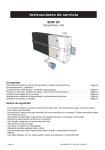
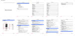
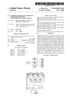
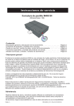
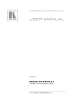
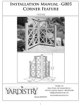
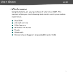
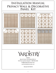
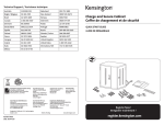
Installation Manual -G006
Corner Climber
YM11554
63 ½”
(1.61m)
(0.51m)
(0.69m)
(0.51m)
(0.69m)
Yardistry Ltd.
Mount Forest, ON Canada N0G 2L1
Toll Free Customer Support: 1.888.509.4382
[email protected]
www.yardistrystructures.com
Revised 08/24/2011
1
!Important Safety Notice!
•
Yardistry components are intended for privacy, decorative and ornamental use only. Product is NOT
INTENDED for the following:
- A safety barrier to prevent unsupervised access to pools, hot tubs, spas, or ponds.
- Safety railings for elevated platforms or decks.
- As load bearing support for a building, structure, heavy objects or swings. - Used in structures that trap
wind, rain or snow that would create extra load on the product.
•
Permanent structures may require a building permit. As the purchaser and or installer of this product you
are advised to consult local planning, zoning, and building inspection departments for guidance on applicable
building codes and or zoning requirements.
•
Wood is NOT flame retardant and will burn. Grills, fire pits and chimneys are a fire hazard if placed too
close to a Yardistry structure. Consult user’s manual of the grill, fire pit or chimney for safe distances from
combustible materials.
•
During installation, follow all safety warnings provided with your tools and use OHSA approved safety
glasses.
•
Some structures may require two or more people to install safely. Check for underground utilities
before digging or driving stakes into the ground!
General Information: Wood components are manufactured with Cedar (C. Lanceolata) which is protected with
factory applied water-based stain. Knots, small checks (cracks) and weathering are naturally occurring and do
not affect the strength of the product. Annual application of a water-based water repellent sealant or stain will help
reduce weathering and checks.
Keys to Assembly Success
Tools
Required
Warranty: Yardistry Limited products are backed by a 5 year limited lifetime warranty from the date of original
retail
purchase
and if installed as• Open
per manufacturer’s
installation
• Tape
Measure for manufacturing
• #1, defects
#2 & #3 Phillips
End Wrench
• 3/16”instructions.
Hex Key
• Carpenters Level
• Carpenters Square
• Claw Hammer
• Standard or Cordless Drill
• Tape Measure
or Robertson Bits
(7/16”, 1/2” & 9/16”)
Patents Pending
or Screwdriver
• Adjustable Wrench
• Ratchet with extension Tools Required
• 1/8” & 3/16” Drill Bits
(1/2” & 9/16” sockets)
• Pencil
• #2 Phillips or Robertson
Bits or Screwdriver
Part
Identification
Key
• Carpenters
Level
On each page, you will find the parts
andDrill Bit
• 1/8”
• Carpenters
Square
quantities
required
to complete the assembly
Pencil
step illustrated on that page. Here• is
a sample.
• Standard or Cordless
Drill
Symbols
• 8’ Step Ladder
• Safety Glasses
• Adult Helpers
• Safety Glasses
• Adult Helpers
2X A1 Post 2 x 4 x83”
• 8’ Step Ladder
Quantity
Key Number
Part Description, Part Size
Throughout these instructions symbols are provided
as To
important
reminders
for proper and safe assembly.
Keys
Assemble
Success
This identifies information that requires special
attention. Improper assembly could lead to an
unsafe or dangerous condition.
Use
Help
Measure
Distance
Use
Help
Check that set or assembly is properly level
before proceeding.
Pre-drill 1/8” & 3/16” Bit
Where this is shown, 2 or 3
people are required to safely
complete the step. To avoid
injury or damage to the
assembly make sure to get help!
Check that assembly is square
before tightening bolts.
Pre-drill a pilot hole
before fastening screw
or lag to prevent
splitting of wood.
Square
Assembly
Tighten
Bolts
This indicates time to tighten bolts, but
not too tight! Do not crush the wood.
This may create splinters and cause
structural damage.
Use a measuring tape to assure
proper location.
No
CAUTION – Protrusion Hazard
Use
Level
2
Yes
If Bolt protrudes
beyond T-Nut
Material List
R
Top and Bottom Rail -2x 7 1/4” (18.4cm) and 2x 20” (50.8cm)
S4
S4
S4
S7
#8 x 2 1/4” Wood Screw
S5
S4
S7
S5
#10 x 1” Pan Head Screw
P
4x4 Posts - 1x 63” (1.60m) and 2x 49 1/4” (1.25m)
S7
S7
S6
S5
#8 x 1 1/2” Wood Screw
S6
S5
(3) Post Caps
S6
(12) Panel Clips
PA1 (2)Arch Topper
PX2 (2) Two High X Panel
3
Insert male into female. Slide down until flush with
also be connected together as
à deux ou à trois carreaux de hauteur
Panels if required.
altos apanel.
medida que se adquieran.
adjacent
purchased.
séparément).
os paneles.*Use 2 1/4" stainless steel screws *Use los tornillos de acero inoxidable (vendus
*Utilisez
vis en acier inoxydable de
de 2 1/4"el
queextremo
se incluyen en
el juego en el les
Introduzca
macho
extremo
hembra.
the Panel
Clip set Wings
to
Step 1-included
Assemble
s supérieures
et inles
panneaux
dans
l'orientation
exigée
pour
votredeprojet.
2-1/4
po
fournies
dans le
nécessaire
de sujetadores de paneles para
Deslícelo hacia abajo
secure and strengthen the assembly.
el ensamblado.
panel reforzar
adyacente.
hasta que
quede
al rasafin
del
fixations
pour panneaux
de fixer et
20"
Two Wide
de renforcer l'assemblage.
1. Remove the upper metal connectors on both sides of PX2 - Two High X Panel. Reattach the metal connectors
Insérez les
pièces
debyraccordement
mâles dans les
Three Wide
Assemble
Panels
side
side.
to PX2 by securing the bottom
two holes
the metal
connectors
to the Faites
top twoglisser
holes on
pièces
deofraccordement
femelles.
le PX2 so that the metal
connectors stick out from theConecte
top.
Slide
PA1
– Arch
Topper
between
the two
los
paneles
lado
a lado.
panneau
vers
le bas
jusqu'à
ce qu'il
soit protruding
au mêmemetal connectors on
the top of PX2. Attach the metal
connectors
to
the
factory
drilled
holes
in
PA1.
(Fig. 1A) *Ensure Panels are
niveau que
panneau
adjacent.
Assemblez
leslepanneaux
côte
à côte.
oriented correctly! (Fig. 1B)
Groove
Four Wide
2
2. Secure panels with a S4 - 2
1/4” Wood Screw the location
indicated by the large arrow in
Notez l'orientation
en direction of the arrow. When
de l'encoche
the
trou de serrure.
pre-drilled holes are not available
use a 1/8” Drill Bit to drill holes on
an angle in the inside of the panel
as shown. (Fig. F)
Skinny Piece
of Wood
Thick Piece
of Wood
Fig. F
R
Note orientation of keyhol
3. Secure R-Top and Bottom Rails to
Panel Assembly with S4 - 2Insert
1/4”male into female. Slide down until flush with adjacent panel.
ectorsWood
and
reattach
Instructions deTenga
base en cuentaCut
atta
laand
orient
Screws
locations using
indicated
Pautas
Introduzca el extremo
machobásicas
en el extremo para
hembra.
Deslícelo
hacia
3. Connect
last assembled
panels to make a fence section.
2
1/4”
Screw
pour l'assemblage
del agujero de la cerradur
d holes
on panel.
ensamblado
de
by arrows
in the direction
ofabajo
thehasta queelquede
Basic
Guidelines
al ras del panel adyacente.
PA1
Corte y fije l
des
panneaux
Drill Hole on an Angle
los paneles
for
Panel
Assembly
arrow. *RTop
and Bottom
Rails
Insérez les pièces de raccordement mâles dans les pièces
de l'enc
Les assemblages illustrés Notez
comportentl'orientation
des
will overhang
1/4”
either using Las ilustraciones muestran
Taillez
et fix
grandes
y Shown
vuelva
a
here
areon
configurations
de raccordement
femelles. Faites
glisser le panneau
en
trou
deserrure.
pièces
supérieures.
Il
est
possible
configuraciones
con
topes.
También
side
of
panel.
Except
on
Arch
avers
Topper.
and 3 High
Panels
canmême niveau que
dos agujeros
le bas2 jusqu'à
ce qu'il
soit au
également d'assembler des panneaux
One Wide
se pueden conectar 2 y 3 paneles
Top and Bottom
Rail will
Topper!!also
be
connected
together
as
le panneau adjacent.
male
à deux ou à trois carreaux de hauteur
3
anel.
altos a medida que se adquieran.
purchased.
* R- Top and Bottom Rails may
*Use los tornillos de acero inoxidable (vendus séparément).
e Small Connectors. *Use 2 1/4" stainless steel screws
*Utilisezthe
les visoutside
en acier inoxydable
Remove
male
connectors
of thede
to be
cutintothe20”
de 2the
1/4" que
se incluyen
en el juego from
èces need
de raccordement
included
Panel(50.8cm)
Clip setet
to
2-1/4
po
fournies
dans
le
nécessaire
de
onectores
panel
assembly.
and
7 1/4”
(18.4cm)
secure
and
strengthen
the assembly. de sujetadores de paneles para
fixations
pour
panneaux
afin
de
fixer
et
au moyen
des
deux
trous
reforzar el ensamblado.
de renforcer
l'assemblage.
(Itpièces
is
recommended
to useàa Mitre
Quite los conectores masculinos
del exterior
de la
au
qui
ont
été percés
les petites
Box or Mitre Saw)
ent.
asamblea de panel.
C.
2
Assemble Panels side by side.
4. Repeat until two panel assemblies
Enlever los
les paneles
connecteurs
Conecte
lado a mâles
lado. de l'extérieur de
are created.
l'assemblée de panneau.
Assemblez les panneaux côte à côte.
actory
holes.
Notezdrilled
l'orientation
en
de l'encoche
eros
pretaladrados.
trou de serrure.
prépercés à l'usine.
*Les vis sont celles de 2-1/4 po en acier inoxydable qui sont fournies dans le nécessaire de fixations pour panneaux.
x2
Insert male into female. Slide down until flush with adjacent panel.
connecteur
mâle Three Wide
1/4"
Los tornillos* son de acero inoxidable de 2 1/4"
y se incluyen en el juego de sujetadores de paneles.
Fig. 1B - Filler Strips on Bottom
of Panel!
through factory drilled hol
On Bottom,Two
space
Screws
conector
Wide
4" from edges of panels.
masculino
short male
Four Wide
connector
Screws* are 2 1/4" stainless
steel included in Panel Clip set.
Pilot holes to the right
20" si
overhang 1/4"on either
connector
Attach Top with Screws*
1/4"
conector
masculino
corto
le connecteur
mâle court
Fig. 1A
Do not remove Smal
Introduzca el extremo macho en el extremo hembra.
Deslícelo
hacia
3. Connect
last assembled
panels to make a fence section.
PX2
abajo hasta que quede al ras del panel adyacente.
No retire
los conecto
R
Insérez les pièces de raccordement mâles dans les pièces
m
er.
de raccordement femelles. Faites glisser le panneau
vers le bas jusqu'à ce qu'il soit au même niveau que
le panneau adjacent.
dera2x PA1 Arch Topper
ón
deConnectors.
e Small
2x
conectores
2x
en bois
PX2
R
Ne retirez pas les pe
raccordement.
Top and Bottom Rail will
2x
R
Top & Bottom Rail At 7 1/4” (18.4cm) overhang 1/4"on either s
8x
S4
#8- 2 1/4” Wood Screws
Two High X Panel
Top & Bottom Rail At 20” (50.8cm)
s les petites pièces
ment.
4
Attach Top with Screws*
through factory drilled ho
On Bottom, space Screw
4" from edges of panels.
Step 2- Attach Panel Clips For Wings
1. On a flat surface place P- 4x4 Post on its side and position Panel Clips in
locations indicated in Figures 1 and 1A. Ensure Panel Clips are oriented
as shown in Diagrams!
Fig. 2
2. Panel Clips should be placed in the centre of the post or the leading edge
of the clip should be 1 3/8” or 3.49cm away from the side of the post as
shown in Fig. 2.
3. With Panel Clips in place, mark screw holes with a pencil and pre-drill
holes with a 1/8” drill bit. (Not provided)
4. Secure Panel Clips in locations indicated in figure 1 and 1A with S7- #8 x 1
1/2” wood screws.
1 3/8”
(3.5cm)
Pre-drill holes and secure with S7- #8 x
1 1/2” Wood Screws
5. Repeat for each post configuration.
Fig. 1A- Top View
C
Note: Post A has Panel
Clips on two sides!
A
B
Side View
Fig. 1
Front View
Fig. 1
A
B
C
(138.2cm)
(111.8cm)
(111.8cm)
38”
(101.6cm)
(96.5cm)
38”
(101.6cm)
(96.5cm)
(20.3cm)
(20.3cm)
2x
P
4x4 Post at 49 1/4” (1.25m)
12x - Panel Clips
1x
P
4x4 Post at 63” (1.60m)
24x S7 #8 x 1 1/2” Wood Screw
5
38”
(101.6cm)
(96.5cm)
(20.3cm)
Step 3- Attaching Post Caps
1. Place a Post Cap on each 4x4 Post
2. Secure Post Cap with 2 S7- #8- 1 1/2” Wood Screws
x3
3x Post Caps
6x 6
S7
#8- 1 1/2” Wood Screws
This identifies information that requires special
Check that set or assembly is properly level
before proceeding.
Step 4- A
ttach
to
attention. Wings
Improper assembly
couldPosts
lead to an
unsafe or dangerous condition.
Use
Use
Pre-drill 1/8” & 3/16” Bit
Where this is shown, 2 or 3
Help
Help
Pre-drill a pilot hole
1. Place panel assemblies on posts as shownpeople
(Fig.1)
a safely
2” gap between
areallowing
required to
before fastening screw
the step.rail
To avoid
the bottom of the post and the bottom edgecomplete
of the bottom
on the panel
or lag to prevent
injury
or
damage
to
the
assembly. Note: Assemble with the help of another adult!
splitting of wood.
assembly make sure to get help!
2. With a 1/8” drill bit, predrill holes as shown in figure 2.
Measure to Check
that and
assembly
is Clips
squarewith aSquare
3. Fasten the panel assembles
the post
Panel
S5- 1” Pan
Distance
Assembly
before
tightening
bolts.
Head Screw provided in location of circles. (Fig. 1)
This indicates time to tighten bolts, but
*Posts must be securely installed
to support structure. Consult local not too tight! Do not crush the wood.
Use a measuring tape to assure
building codes and ground conditions
for required footing design. It is This may create splinters and cause
proper location.
recommended the structure be secured to existing stone, concrete or structural damage.
deck.
Fig. 2. Predrill Holes and Fasten
No S5- 1” Pan Head Screw
with
If Bolt protrudes
beyond T-Nut
CAUTION – Protrusion Hazard
1
Once the assembly is tightened, watch forFig.
exposed
threads. If a thread protrudes from the T-Nut, remove
the bolt and add washers to eliminate this condition.
Extra washers have been provided for this purpose.
Use an extra
Flat Washer
Lag Screw
For bolts, tap T-Nut into hole with
hammer. Insert the hex bolt through
lock washer first then flat washer then
hole. Because the assemblies need to
be squared do not completely tighten
until instructed. Pay close attention to
diameter of the bolts. 5/16” is slightly
larger than 1/4”.
Before mounting
use factory drilled
guides to drill 1/8
Flat Washer
Bolt Assembly
Hex Bolt
Lock
Washer
Note: Wafer head bolts with blue lock
tight or a bolt with a Ny-Lok nut do
NOT require a lock washer.
Flat
Washer
6
12x
P
2” (5.1cm)
Ye
Lag Assembly
Proper Hardware Assembly
Lag screws require drilling pilot
holes to avoid splitting wood. Only
a flat washer is required. For ease of
installation liquid soap can be used
on all lag-type screws.
B
Tigh
Bo
A
2” (5.1cm)
C
4x4 Post
12x S5 #10 x 1” Pan Screws
7
T-Nut
(Hammer
Do not cr