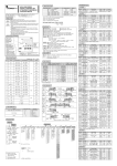
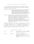
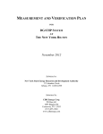
1
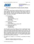
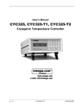
masibus
LC5296/5006-RN/LC5296H
Temperature Controller
Ref No: m61C/om/101
Issue No: 02
User’s Manual
L C 5 2 96/ 5 0 0 6- R N/ L C 5 2 96H T e m p e r a t u r e
C o nt r o l l e r
Masibus Automation & Instrumentation Pvt. Ltd.
B/30, GIDC Electronics Estate,
Sector-25, Gandhinagar-382044, Gujarat, India
Email: [email protected]
Web: www.masibus.com
User’s Manual
Page 1 of 19
LC5296/5006-RN/LC5296H
Temperature Controller
Ref No: m61C/om/101
Issue No: 02
masibus
Contents
(1) TEMPERATURE CONTROLLER OVERVIEW
(04)
(2) SPECIFICATIONS
(06)
2.1:
2.2:
2.3:
2.4:
2.5:
2.6:
2.7:
2.8:
2.9:
Displays
Inputs
Input Range
Accuracy
Output
Calibration
Types of Set points
Power Supply
Environmental condition
(3) MOUNTING DETAILS
(07)
(4) TERMINAL CONNECTION
(08)
(5) FRONT PANEL DESCRIPTION
(09)
(6) CONFIGURATION MODE
(09)
6.1: Password mode
6.2: Configure Input Type
6.3: Configure Zero
6.4: Configure Span
6.5: Configure Setpoint-1
6.6: Configure Setpoint-2
6.7: Configure Open Sensor
6.8: Configure Decimal Point
6.9: Configure Display set Point
6.10: Configure Brightness
6.11: Configure Serial number
6.12: Configure Baud rate
6.13: Configure Relay Delay 1
6.14: Configure Relay Delay 2
6.15: Configure Retransmission-1 type
6.16: Configure Retransmission-2 type
6.17: Configure Hysterisis 1
6.18: Configure Hysterisis 2
6.19: Configure change user’s password
6.20: Version No.
(7) RUN MODE
(12)
7.1: Set Value of Setpoint-1
7.2: Set Value of Setpoint-2
7.3: See Value of Ambient
(8) CALIBRATION MODE
User’s Manual
(13)
Page 2 of 19
masibus
LC5296/5006-RN/LC5296H
Temperature Controller
Ref No: m61C/om/101
Issue No: 02
8.1:
8.2:
8.3:
8.4:
8.5:
8.6:
8.7:
Calibration
Calibration
Calibration
Calibration
Calibration
Calibration
Calibration
of
of
of
of
of
of
of
Ambient
Zero
Span
Retransmission-1
Retransmission-1
Retransmission-2
Retransmission-2
Zero
Span
Zero
Span
(9) APPLICATIONS OF LC5296 TEMPERATURE CONTROLLER
(13)
(10) MODBUS RTU PROTOCOL ADDRESSES FOR RS 485 COMMUNICATION (14)
(11) Maintenance
(19)
Figures
Figure 1: Typical Relay Operation
(05)
Figure 2: Mounting Details
(07)
Figure 3: Terminal Connections
(08)
Figure 4: Lead Termination
(08)
Figure 5: RS-485 Communication Detail
(08)
Figure 6: Details of Front Panel
(09)
Figure 7: Direct Load connected With Line
(14)
Figure 8: Direct Load Connected With Neutral
(14)
Note:
User’s Manual
Page 3 of 19
LC5296 Temperature Controller
Ref No: m61C/om/101
Issue No: 00
masibus
Information in this manual is subject to change without prior
notice or permission.
Warning Symbol
The symbol calls attention to the operating procedure,
practice or the like which if not correctly performed or adhered to , could result
in personal injury or damage to or destruction of part or all of the product and
system. Do not proceed beyond a warning symbol until the indicated condition
are fully understood and met.
Class-2 Type of instrument
Note: Class-2 – Instrument is using Line & Neutral for Power Supply
Input.
1.0
TEMPERATURE CONTROLLER OVERVIEW
Model LC5296/5006-RN is a microcontroller based On/Off
Temperature controller, incorporate bright, 4 Digit Seven Segment Display
indicating process value and set value.
ON/OFF Controller is the simplest form of temperature control
device. The output from the device is either on or off, with no middle state. An
on-off controller will switch the output only when the temperature crosses the
setpoint. For heating control, the output is on when the temperature is below the
set point, and off above set point.
Since the temperature crosses the set point to change the output
stage, the process temperature will be cycling continually, going from below set
point to above, and back below. In cases where this cycling occurs rapidly, and
to prevent damage to contactors and valves, an on-off differential, or
“hysterisys,” is added to the controller operations. This hysterisys assures, if
temperature exceed set point by a certain amount before then only output will
turn off or on again. On-Off hysterisys prevents the output from “chattering” or
making fast, continual switches if the cycling above and below the set point
occurs very rapidly.
User’s Manual
Page 4 of 19
LC5296 Temperature Controller
Ref No: m61C/om/101
Issue No: 00
masibus
Figure 1: Typical Relay operation
High type:
For High type of set value, once process value reaches up to set
point + Hysterisys value, relay will be ON and it will be ON until process value
goes down to Set point.
Low type:
For Low type of set value, once process value reaches down to set
point + Hysterisys value relay will be ON and it will be ON until process value
goes up toward Set point.
On/Off control is usually used where a precise control is not
necessary, in systems which cannot handle having the energy turned on
and off frequently, where the mass of the system is so great that
temperature change extremely slowly.
User’s Manual
Page 5 of 19
masibus
LC5296 Temperature Controller
Ref No: m61C/om/101
Issue No: 00
2.0
SPECIFICATIONS
2.1 DISPLAYS:
•
LC5296:
•
•
•
4 digits 0.56" Seven Segment Red
LED’s for Process Variable in °C.
4 digits 0.40" Seven Segment Green
LED’s for Status Variable in °C.
Individual discrete Red LED’s to
indicate
relay
status
and
communication (Rx and Tx).
5006-RN:
•
•
2.4 ACCURACY:
4 digits 0.56" Seven Segment Red
LED’s for Process Variable in °C.
Individual discrete Red LED’s to
indicate
relay
status
and
communication (Rx and Tx).
•
2.5 OUTPUT:
•
Relay O/P:
Rating: 2A/230VAC
•
Re-transmission 1:
Type: 4-20 mA, 0-20 mA
Load: 500 Ohms Max
Type: 0-5 V DC, 1-5 V DC, 0-10 V
DC
Load: 2K minimum
Isolation: 500VDC
Accuracy: ±0.25% of Full scale
•
Re-transmission - 2:
Type: 4-20 mA, 0-20 mA
Load: 500 Ohms Max
Type: 0-5V DC, 1-5V DC, 0-10V DC,
Load: 2K minimum
Isolation: 500VDC
Accuracy: ±0.25% of Full scale
LC5296H:
•
•
4 digits 0.56" Seven Segment Red
LED’s for Process Variable in °C.
Individual discrete Red LED’s to
indicate
relay
status
and
communication (Rx and Tx).
2.2 INPUTS:
•
•
•
•
•
•
•
•
•
RTD - PT100 3-wire
(Automatic 3 wire compensation)
RTD – PT100(0.1°C).
Thermo-couple types J, K, T, R, S
(ANSI standard) (Cold junction
compensation)
4-20mA/1-5 V dc linear
0-20mA/0-5 V dc linear
Burn out Current : 0.25 uA
CMRR : > 120dB
NMRR : > 40dB
Input Impedance : > 1MΩ
* +/- (0.25% of Full Scale + 1
degree) for T/C and RTD input.
* +/- (0.25% of Full Scale + 1
count) for Linear input.
• Subject to recalibration for i/p
change.
•
Transmitted Power Supply:
24VDC @ 30mA (±10% Accuracy)
•
Isolated RS485 Communication:
Protocol: Modbus RTU
Parity: None
Baud Rate: 9600, 19.2k, 38.4k.
Isolation: 500VDC
2.3 INPUT RANGE:
PT100
:
PT100 (0.1ºC) :
J
:
K
:
T
:
R
:
S
:
-200 to 850 ºC
-199.9 to 850.0 ºC
-200 to 1200ºC
-200 to 1372ºC
-100 to 400ºC
0 to 1768ºC
0 to 1768ºC
4-20mA/1-5VDC, 0-20mA/0-5VDC:
-1999 to 9999 (Field Scalable)
User’s Manual
2.6 CALIBRATION:
•
•
•
•
Zero and Span calibration using
front key pad.
Auto zero calibration in
thermocouple (T/C) type input.
CJC (Cold Junction
Compensation) for T/C type input
And Software 3-wire lead
Compensation for RTD sensor.
Instrument Warm-up Time < 30 Min.
Page 6 of 19
masibus
LC5296 Temperature Controller
Ref No: m61C/om/101
Issue No: 00
2.7 TYPES OF SET POINT:
•
•
Set point types are configurable to
energize relays for actual value
below or above set point with delay
time for individual Relay.
Hysteresis setting 1 to 100 Counts.
3.0
MOUNTING DETAILS
LC5296/5006-RN:
2.8 POWER SUPPLY:
•
•
Operating Supply:
85-265VAC @ 50Hz
18-36VDC (Optional)
Power consumption:
< 10 VA
2.9 ENVIRONMENTAL
CONDITION:
•
Insulation Resistance:
>50MΩ @ 500VDC
•
Isolation Specifications:
Measured Input terminal: Isolated
from other Output terminals & Not
isolated from the internal circuit.
24V DC Supply[TPS]: Isolated from
other output terminals & Not isolated
from the internal circuit & input.
Retransmission
output
terminal:
Isolated
from
input
terminals
&
communication terminal.
RS-485 communication terminal:
Isolated from Input terminals & isolated
from the Other Output terminal.
Relay Contact o/p terminal: Isolated
from input terminals, internal circuit and
other output terminals.
Retransmission
output1
&
Retransmission output1 terminal:
Non Isolate from each other and
Isolated from Input Terminals.
Power supply terminal: Isolated from
other input and Output terminals and
internal circuit.
•
•
•
•
•
Molding type: ABS Plastic
Weight: 300 Gms Appx.
Ambient Temperature:
0 to 55 °C
Humidity:
20 to 95% RH non-condensing
Storage Temperature:
0-80 °C
User’s Manual
LC5296H:
Figure 2: Mounting Detail
LC5296/5006-RN:
FRONT BEZEL: 96 x 96 mm
PANEL CUTOUT:
92mm (+0.8) x 92mm(+0.8)
• DEPTH BEHIND THE PENAL:
65.0mm
LC5296H:
• FRONT BEZEL: 48 x 96 mm
• PANEL CUTOUT:
45 (+0.6)mm x 92 (+0.8)mm
• DEPTH BEHIND THE PENAL:
75.0mm with Terminal
•
•
Note:
UNPACKING: Upon receipt of
the shipment remove the unit form
the carton and inspect the unit for
Page 7 of 19
masibus
LC5296 Temperature Controller
Ref No: m61C/om/101
Issue No: 00
shipping damage. If any damage
due to transit, report and claim with
the carrier. Write down the model
number, serial number, and date
code for future reference, when
communicating with our Customer
Support Division.
Use external switch or circuit
breaker and external over current
protection devices to protect whole
panel or instrument in hazardous
condition.
Do not use this instrument in
areas such as excessive shock,
vibration, dirt, moisture, corrosive
gases
or
rain.
The
ambient
temperature of the areas should not
exceed
the
maximum
rating
specified.
4.0
1
2
+ 24V
C+
3
+
+
9
L/ +
Sr. No.
INPUT
RANGE
POWER
-
-4
*-
5
6
T/C
RTD
mA
Volt
7
8
Rx2+
/D+
Rx2/D-
*2 5 0 Ohm , 0 .1 % U s e E x te r na lly
10
11
12
13
14
15
16
N/
C2
NO 2
NC2
C1
NO 1
NC1
85-265VAC
18-30VDC
OUTPUT
24VTPS
2
Rx-O/P 1
COMM.
Class-2
www.masibus.com
Figure 3: Terminal connection
LC5296/5006-RN:
1. Terminal 2 & 3 & 4:
For Relay-1 potential free
Contacts (Use 230V -2A load)
2. Terminal 5 & 6 & 7:
For Relay-2 potential free
Contacts (Use 230V -2A load)
TERMINAL CONNECTIONS
LC5296/5006-RN:
2
+24V
11
C+
12
V+
13
GND
14
Rx1+
17
Rx1-
18
Rx2+/D+
19
Rx2-/D-
20
NC1
Figure 4: Lead Termination
RTD
3
NO1
+
*m A
4
C1
5
NC2
6
NO2
7
C2
8
9
N/
10
L/+
LC5296H:
-
+
V
-
+
T/C
-
*
3. Terminal 9 & 10:
Power Supply Input
(85-265VAC @ 50Hz /
120-290VDC).
24VDC (Optional)
4. Terminal 11:
+24V Transmitted power supply
Output.
5. Terminal12:
For RTD Input Only (Three wire
Compensation – c+ terminal).
6. Terminal 13 & 14:
For T/C & Linear Input
7. Terminal 17 & 18:
For retransmission no. 1 output
8. Terminal 19 & 20:
For retransmission no. 2 output
or
Communication.
LC5296H:
1. Terminal 14 & 15 & 16:
User’s Manual
Page 8 of 19
masibus
LC5296 Temperature Controller
Ref No: m61C/om/101
Issue No: 00
2.
3.
4.
5.
6.
7.
8.
or
For Relay-1 potential free
Contacts (Use 230V -2A load)
Terminal 11 & 12 & 13:
For Relay-2 potential free
Contacts (Use 230V -2A load)
Terminal 9 & 10:
Power Supply Input
(85-265VAC @ 50Hz /
120-290VDC).
24VDC (Optional)
Terminal 1:
+24V Transmitted power supply
Output.
Terminal 2:
For RTD Input Only (Three wire
Compensation – c+ terminal).
Terminal 3 & 4:
For T/C & Linear Input
Terminal 5 & 6:
For retransmission no. 1 output
Terminal 7 & 8:
For retransmission no. 2 output
Communication.
3. Switch off the power before
wiring.
4. Supply voltage must be below
maximum voltage rating specified
on the label.
5. All wiring must confirm to
appropriate standards of good
practice and local codes and
regulations. Wiring must be
suitable for Voltage, Current and
temperature rating of the system.
6. Unused control terminals should
not be used as jumper points as
they may be internally connected,
which may cause damage to the
unit.
Note:
1) Use >250V-1Amp Cable for
Power Supply.
2) If cable has two parallel wires
inside then isolation between them
must be 2.5 KV.
5.0
19
20
FRONT PANEL
DESCRIPTION
LC5296/5006-RN:
19
20
19
20
Figure 5: RS-485 Communication
Detail
Note:
1. Use Repeater after each and
every
set of 32 instruments.
2. Do not connect 3rd terminal (C+)
when linear or TC input is
selected.
User’s Manual
Page 9 of 19
masibus
LC5296 Temperature Controller
Ref No: m61C/om/101
Issue No: 00
menu of Conf mode.
1001
SET1
6.0
Press
Key together to enter
configuration
mode
after
entering
correct password.
SET2
6.1
LC5296H:
PV
SET2
SET2
100
.1
LC5296H
1. Increment Key:
- Increment value in PV window.
2. Decrement Key:
-Shows ambient value for T/C
Input in run mode.
- Decrements value in
PV window.
3. SET-1 key:
On pressing this key set value-1
is displayed in PV window.
4. SET-2 key:
On pressing this key set value-2
is displayed in PV window.
5. PV window:
- 4 digital 0.56 inch RED Display.
6. SV window:
- 4 digital 0.28 inch GREEN
Display.
7. Relay-1 Indication:
- ON when relay-1 is energized.
8. Relay-2 Indication:
- ON when relay-2 is energized.
9. Set Value-1 Indication:
- ON when set-1 is saved in Disp
menu of Conf mode.
10. Set Value-2 Indication:
- ON when set-2 is saved in Disp
PASSWORD
Display
PASS
Press
1
Press
ConF
Once correct password is entered,
Configure mode is displayed.
6.2
Figure 6: Details of Front Panel
User’s Manual
MODE
, the
Note: When user Press
Parameters will change in SV window for
LC5296 Model.
5006-RN
SET1
SET1
CONFIGURATION
6.3
6.4
CONFIGURE INPUT TYPE
Display
ConF
Press
InPt
Press
tC K
Press
InPt.
Press
to configure ZERO,
CONFIGURE ZERO
Display
zero
Press
-100
Press
zero.
Press
to configure SPAN
CONFIGURE SPAN
spaN
Display
Press
1200
Press
spaN.
Press
to configure SET POINT1
Page 10 of 19
masibus
LC5296 Temperature Controller
Ref No: m61C/om/101
Issue No: 00
6.5
6.6
6.7
CONFIGURE SET POINT 1
TSP1
Display
Press
L on
Press
TSP1.
Press
to configure SET POINT2,
CONFIGURE SET POINT 2
Display
tSP2
Press
St-1
Press
dIsp.
Press
6.10
Press
Press
TSP2.
Press
Press
to configure OPEN
SENSOR,
CONFIGURE OPEN SENSOR
Display
oPES
Press
POINT,
UP
Press
6.11
Press
Press
6.12
CONFIGURE DP
Note: This option is available
only when the selected input
type is linear (0-5V or 1-5V),
else it’s not displayed.
Press
Press
dP
1
dP.
Press
to configure Display set
Point,
CONFIGURE
DISPLAY
SET
POINT
User’s Manual
brht.
to configure Serial Number
CONFIGURE SERIAL NUMBER
Display
SrNO
Press
to configure DISPLAY SET
Up scale: Under Open condition
PV is treated above set point.
Display
50
For
Communication
Feature,
following Parameters are there
in configuration mode.
oPES.
Down
scale:
Under
Open
Condition PV is treated below set
point.
to configure Brightness,
CONFIGURE BRIGHTNESS
brht
Display
H on
Press
6.9
dIsp
Press
Press
6.8
Display
SrNO.
to configure Baud Rate,
CONFIGURE BAUD RATE
Display
bAUd
Press
9600
Press
bAUd.
Press
Relay1,
6.13
1
to configure Delay time for
CONFIGURE RELAY1 DELAY
TIME
rd1
Display
Press
Press
Press
Relay2,
5
rd1.
to configure Delay time for
Page 11 of 19
masibus
LC5296 Temperature Controller
Ref No: m61C/om/101
Issue No: 00
6.14
Press
Press
rd2.
Press
to configure
Retransmission - 1 type volt.
Press
6.18
Press
Display
rt 1
Press
Press
0-10
Press
rt 1.
Press
6.19
Press
to configure
RETRANSMISSION-2 TYPE CURRENT
Retransmission2/Communication
is optional. Either of them will be
available. For retransmission2
Feature, following Parameters
are available in configuration
mode.
6.16
6.17
rt 2
Press
4-20
Press
rt 2.
Press
to configure Hysterisis-1
TO SET VALUE OF
HYSTERISIS 1
User’s Manual
HY-1.
to configure Hysterisis-2
HY-2
2
+
HY-2.
to configure Pass word
CONFIGURE
CHANGE PASSWORD
Display
Pass
Press
0
Press
Press
6.20
Pass.
to configure Conf. mode
VERSION NO
Display
VErS
Display on SV window 01.00
CONFIGURE
RETRANSMISSION-2 TYPE
Display
1
+
TO SET VALUE OF
HYSTERISIS 2
Display
CONFIGURE
RETRANSMISSION-1 TYPE
Note: If retransmission current
type is selected then
retransmission voltage type
cannot be selected, at a time only
one will work while the other will
lock.
HY-1
Press
5
Press
6.15
Display
CONFIGURE RELAY2 DELAY
TIME
Rd2
Display
Press
VErS.
Press
COnF.
Press
Key together to come out
of configuration mode or in Run Mode.
Now Instrument is in Run Mode.
7.0
RUN MODE
In Run mode, press
for configure
Setpoint-1 and Press
Setpoint-2.
for configure
7.1
TO SET VALUE OF SET POINT1
Page 12 of 19
masibus
LC5296 Temperature Controller
Ref No: m61C/om/101
Issue No: 00
Display
If thermocouple input type, then
calibration of zero will not be
displayed.
CALZ
Display
St-1
Press
100
+
To change Set Point1 Value.
7.2
TO SET VALUE OF SET POINT2
st-2
Display
Press
-099
Press
CALZ.
Press
Press
100
+
8.3
To change Set Point2 Value
7.3
TO SEE AMBIENT
30.0
Press
To Check Ambient Value in Run
mode.
8.0
Press
1
Press
ConF
Press
CAL
Press
mode.
enter calibration
CALIBRATION OF AMBIENT
AMb
Display
CALIBRATION OF SPAN
Display
CALS
Press
1099
Press
CALS.
Press
to calibrate
RETRANSMISSION-1 ZERO.
Steps to calibrate Retransmission
o/p: -
while calibrating the retransmission output, input is
not required. When entered in rx-zero calibration
submenu,
respective
zero
output
will
be
transmitted. To calibrate the rx-zero, simply
increment or decrement the counts until correct
value obtained.
Example:
If Rx o/p type:- 4-20mA
Rx-zero calib o/p:- 4.12mA
Now, press decrement until the o/p value
Becomes 4.00mA. At this point, number of
counts decremented will be displayed on
SV window. Follow similar steps to
calibrate Rx. Span.
8.4
CALIBRATION OF
RETRANSMISSION-1 ZERO
Display
23.8
Press
Press
AMb.
(Adjust req. Amb. value)
Press
Press
Press
8.2
calibrate Span.
CALIBRATION MODE
Press
Key together to enter
configuration
mode
after
entering
correct password.
PASS
Display
8.1
to
to calibrate Zero,
CALIBRATION OF ZERO
User’s Manual
rtZ1
0
rtZ1.
Press
to calibrate
RETRANSMISSION-1 SPAN.
8.5
CALIBRATION OF
RETRANSMISSION-1 SPAN
rtS1
Display
Page 13 of 19
masibus
LC5296 Temperature Controller
Ref No: m61C/om/101
Issue No: 00
Press
RETRANSMISSION-2 SPAN
Display
rtS2
0
Press
rtS1.
Press
Press
Press
to calibrate
RETRANSMISSION-2 ZERO.
8.6
Press
CALIBRATION OF
RETRANSMISSION-2 ZERO
rtZ2
Display
Press
rtS2.
to configure Cal mode .
Display
Cal
Press
Key together to come out
of calibration mode to Run Mode.
0
Press
0
rtZ2.
Note: Amb calibration is only
available with J,K,R,T,S - T/C
input.
Press
to calibrate
RETRANSMISSION-2 SPAN,
8.7
CALIBRATION OF
9.0
Applications Of LC5296 Temperature Controller:
L
L
RELAY
LOAD
LC5296
Temp.
NC N
O
Controller
C
N
N
Figure 7: Direct Load Connected with Line
L
L
LC5296
C
Temp.
Controller
NC NO
LOAD
RELAY
N
Note:
User’s Manual
N
Figure 8: Direct Load Connected with Neutral
Page 14 of 19
masibus
LC5296 Temperature Controller
Ref No: m61C/om/101
Issue No: 00
1. Relay has three potential free terminals C, NC & NO. User can use according
to application either C to Line or Neutral.
2. The application Figure is for reference only.
10 COMMUNICATION PROTOCOL – MODBUS-RTU DETAILS:
INTRODUCTION
The unit can be connected in RS-485 communication data link either in multi drop
or repeat mode. Each unit must have unique Serial Number. Entire range of addresses
(1 to 247) may be used. Before starting any communication, choose a baud rate
compatible to the host computer. The serial protocol used is MODBUS RTU.
Protocol details:
The function codes used Read Write of parameters are:
03. – READ HOLDING REGISTERS (REFERENCE - 4x).For Read operation
06. – PRESET SINGLE REGISTER (REFERENCE - 4x).For Write operation
The error checking field contains a 16-bit value implemented as two eight-bit bytes. The
error check value is the result of a Cyclical Redundancy Check (CRC) calculation
performed on the message contents.
Modbus RTU protocol addresses for RS 485 Communication
Sr.
No.
Analog Parameters
Absolut
e
Address
Type
Access Type
Model
Model
LC5296
LC5296H
/5006RN
1
PROCESS VALUE
30001
Int
Read Only
√
√
1
Input Type
40001
Int
Read/Write
√
√
40002
Int
Read/Write
√
√
√
√
√
√
2
Zero
3
Span
40003
Int
4
SET Type-1
40004
Int
Read/Write
Read/Write
5
SET Type-2
40005
Int
Read/Write
√
√
6
Open Sensor Status
40006
Int
Read/Write
√
√
7
Decimal Point
40007
Int
Read/Write
√
√
8
Display set point
40008
Int
Read/Write
√
NA
9
Brightness
40009
Int
Read/Write
√
√
10
Serial Number
40010
Int
Read/Write
√
√
11
Baud Rate
40011
Int
Read/Write
√
√
12
Relay Delay -1
40012
Int
Read/Write
√
√
13
Relay Delay -2
40013
Int
Read/Write
√
√
14
Retransmission o/p
Type -1
40014
Int
Read/Write
√
√
15
Retransmission o/p
40015
NA
NA
NA
User’s Manual
Page 15 of 19
masibus
LC5296 Temperature Controller
Ref No: m61C/om/101
Issue No: 00
Type -2
16
Hysterisis 1
40016
Int
17
Hysterisis 2
40017
Int
18
Pass word
40018
Int
19
Set Value 1
40019
Int
20
Set Value 2
Note: NA = Not Applicable.
40020
Int
Read/Write
√
√
Read/Write
√
√
Read/Write
√
√
Read/Write
√
√
Read/Write
√
√
Note:
1) The possible values to be entered through modbus for above parameter’s in
Table are as follows:
a) Input Type (Applicable values : 0 to 9):
Input Type
J-tc
T-tc
K-tc
R-tc
S-tc
Rtd
Rtd.1
0 – 5V
1 – 5V
Value
0
1
2
3
4
5
6
7
8
b) Set point Type -1 / Set point Type -2 :
Type
L-on
h-on
Value
0
1
c) SET VALUE-1 HYSTERESIS / SET VALUE-2 HYSTERESIS:
(Applicable Values: 0 to 100)
d) Open Sensor Status:
Type
DN(down)
UP
Value
0
1
e) Decimal Position :
Input Type
Rtd
Rtd.1
J-tc
K-tc
T-tc
R-tc
User’s Manual
Maximum Value
0
0
0
0
0
0
Page 16 of 19
masibus
LC5296 Temperature Controller
Ref No: m61C/om/101
Issue No: 00
S-tc
1 – 5v
0 – 5v
0
3
3
f) Display Set Point:
Type
Set point - 1
Set point - 2
Value
0
1
g) Brightness : (Applicable Values : 0 to 100)
h) Serial Number : (Applicable Values : 0 to 255)
i) Baud Rate :
Type (bps)
9600
19200
38400
Value
0
1
2
j) Relay Delay-1/ Relay Delay-2: (Applicable Values : 0 to 99)
k) Retransmission o/p Type -1/2: (Applicable Values : 0 to 99)
Type (bps)
0-10V
0-5V
1-5V
4-20mA
0-20mA
Value
0
1
2
3
4
l) Pass word: (Applicable Values : 0 to 99)
m) Hysterisis 1/2: (Applicable Values : 0 to 100)
n) Set Value 1: (Applicable Values : >Zero & <Span)
9.4:
EXCEPTION RESPONCE:
CODE
MEANING
01
Function code Invalid. It must be 01, 05, 03 or 06.The function code received in the query is not
allowable action for the slave.
02
Illegal address value. The data address received in the query is not an allowable address for the
salve.
03
Illegal data value. A value contained in the query data field is not an allowable value for the
salve.
Table 4: Exceptional Response
User’s Manual
Page 17 of 19
masibus
LC5296 Temperature Controller
Ref No: m61C/om/101
Issue No: 00
10.0 Parameter Description:
Mode of Operation
Conf
Description
Configuration
Mode
Message
inp
J tc
T tc
K tc
R tc
S tc
rtd
Rtd.1
0-5V
1-5V
Zero
Span
Cal
Calibration Mode
Tsp1 or tsp2
l-on
h-on
Dp
Opes
dISP
brht
Srno
Baud
Rd1
Rd2
Rt 1
Hy-1
Hy-2
PASS
vErS
AMb
CALZ
CALS
Rtz1
User’s Manual
Description
Input Type
J type T/C Input
T type T/C Input
K type T/C Input
R type T/C Input
S type T/C Input
RTD Input (1%)
RTD Input (0.1%)
0 -5V Linear Input
1 -5V Linear Input
Zero setting for
input
Span setting for
input
Type of setpoint
High type setpoint
Low type setpoint
Decimal Point
Open sensor
Serial number
Baud rate
Relay1 Delay Time
Relay2 Delay Time
Types of Rx O/P 1
HYSTERESIS 1
HYSTERESIS 2
PASSWORD
S/W version No.
Calibration
Ambiant
Calibration
Zero Value
Calibration
Span Value
Calibration of
Page 18 of 19
of
of
of
masibus
LC5296 Temperature Controller
Ref No: m61C/om/101
Issue No: 00
Rts1
Rtz2
Rts2
Process Value on
PV Window.
Run mode
Open*
Derr*
Retransmission
Output Zero1
Value
Calibration of
Retransmission
Output Sapn
1Value
Calibration of
Retransmission
Output Zero2
Value
Calibration of
Retransmission
Output Sapn
2Value
Open
Sensor
indication
Data Error
11 Maintenance:
Dangerous voltages capable of causing death are sometimes present in
this instrument. Before installation or beginning of any troubleshooting
procedures the power to all equipment must be switched off and isolated. Units
suspected of being faulty must be disconnected and removed first and brought
to a properly equipped workshop for testing and repair. Component
replacement and interval adjustments must be made by a company person
only.
User’s Manual
Page 19 of 19