1
Embedded Solutions
20F206-00 E5 – 2012-03-21
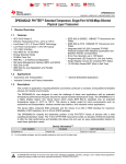
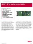
F206 – 3U CompactPCI® Octal
UART for SA-Adapters™
Configuration example
User Manual
®
F206 – 3U CompactPCI® Octal UART for SA-Adapters™
F206 – 3U CompactPCI® Octal UART for SA-Adapters™
The F206 is a universal octal UART based on 3U CompactPCI®. The physical layer
can be realized individually for each channel by means of SA-Adapters™.
SA-Adapters™ are small universal boards providing the physics for legacy serial I/
O, fieldbus interfaces and other small I/O functions. Most SA-Adapters™ use 9-pin
D-Sub connectors which are accessible at the front panel. Alternatively, the adapter
can be connected to the front panel via ribbon cable. The SA concept allows to add
additional I/O interfaces to the F206, enhancing flexibility with regard to the line
transceivers and isolation requirements.
Two SA-Adapters™ can be mounted directly on the F206 (single-slot solution), the
other maximum six adapters need more front-panel space and are connected to the
carrier via ribbon cable. Especially useful adapters for the F206 are isolated and
non-isolated adapters for RS232, RS422 and RS485 interfaces. Different types can
be used on one F206.
The octal UART is realized by means of an FPGA. The register set is fully 16450
compatible, even with larger, 60-byte FIFOs.
The FPGA is loaded automatically after power-up from a 2-MB standard NOR
Flash device. It is also possible to access this Flash from the CompactPCI® bus to
update its contents. There is a primary and a secondary FPGA filling in the Flash.
Normally just the secondary code is used. Only in case of a fault during the update
process the primary contents allow another update of the Flash from the
CompactPCI® bus.
Optionally also 16 MB SDRAM can be installed to complement the functions of the
FPGA. This DRAM can be used for example as a large buffer memory for more
complex protocols.
The F206 is designed for use in rugged environments. For example, all components
are specified for an operating temperature of -40 to +85°C.
MEN Mikro Elektronik GmbH
20F206-00 E5 – 2012-03-21
2
Technical Data
Technical Data
UARTs
•
•
•
•
Up to eight UARTs
Accessible via onboard connectors
Physical interface at front panel using SA-Adapters™ via 10-pin ribbon cable
Different variations with SA-Adapters™ possible:
- RS232
- RS422
- RS485
• Data rates up to 2 Mbit/s
• 60-byte transmit/receive buffer
• Handshake lines: full support; lines depend on SA-Adapters™
FPGA
• Standard factory FPGA configuration:
- Main bus interface
- 16Z054_SYSTEM – System unit
- 16Z025_UART – UART controller (controls four UARTs)
- 16Z025_UART – UART controller (controls four UARTs)
- 16Z045_FLASH – Flash interface
• The FPGA offers the possibility to add customized I/O functionality. See FPGA.
• Option matrix showing possible IP cores and SA-Adapters™ (PDF)
Miscellaneous
• Four status LEDs
Local PCI Bus
• 32-bit/33-MHz, 3.3 V V(I/O)
• Compliant with PCI Specification 2.2
CompactPCI® Bus
• Compliance with CompactPCI® Core Specification PICMG 2.0 R3.0
• Peripheral slot
• V(I/O): +3.3 V
Electrical Specifications
• Supply voltage/power consumption:
- +5 V (-3%/+5%), current depends only on mounted SA-Adapters™
- +3.3 V (-3%/+5%), > 500 mA typ.
Mechanical Specifications
•
•
•
•
•
Dimensions: conforming to CompactPCI® specification for 3U boards
Single 3U front panel slot for up to two UARTs
Up to two supplementary front panel slots required for overall eight UARTs
Front panel: aluminum with 1 handle
Weight: 95 g
MEN Mikro Elektronik GmbH
20F206-00 E5 – 2012-03-21
3
Technical Data
Environmental Specifications
• Temperature range (operation):
- -40..+85°C (qualified components)
- Airflow: min. 1.0 m/s
• Temperature range (storage): -40..+85°C
• Relative humidity (operation): max. 95% non-condensing
• Relative humidity (storage): max. 95% non-condensing
• Altitude: -300 m to +3000 m
• Shock: 15 g, 11 ms (EN 60068-2-27)
• Bump: 10 g, 16 ms (EN 60068-2-29)
• Vibration (sinusoidal): 1 g, 10 Hz - 150 Hz (EN 60068-2-6)
• Conformal coating on request
MTBF
• 308 000 h @ 40°C (derived from MIL-HDBK-217F)
Safety
• PCB manufactured with a flammability rating of 94V-0 by UL recognized manufacturers
EMC
• Tested according to EN 55022 (radio disturbance), IEC 61000-4-2 (ESD) and
IEC 61000-4-4 (burst)
Software Support
• Driver software for Windows®, Linux, VxWorks®, QNX®
• Flash update tools for Windows®, Linux, VxWorks®
• For more information on supported operating system versions and drivers see
online data sheet.
MEN Mikro Elektronik GmbH
20F206-00 E5 – 2012-03-21
4
Block Diagram
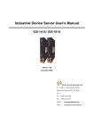
Block Diagram
Configuration
Flash
F
Front connector
B
Onboard connector
SA
SA‐Adapter™
Options
4 HP
4 HP (additional)
F
SA
B
UART
F
SA
B
UART
F
SA
B
UART
F
SA
B
UART
F
SA
F
UART
SA
UART
B
MEN Mikro Elektronik GmbH
20F206-00 E5 – 2012-03-21
F
SA
UART
F
SA
UART
FPGA
Cyclone™
EP1C12
CompactPCI® J1
4 HP
5
Configuration Options
Configuration Options
Physical Layers
• Via up to eight SA-Adapters™
• Different variations possible through FPGA IP cores and SA-Adapters™:
- RS232
- RS422
- RS485
- IBIS master/slave
- CAN bus
- HDLC
- Binary I/O
- InterBus-S
- GPS
- Other physical layers dependent on FPGA configuration
- Option matrix showing possible IP cores and SA-Adapters™ (PDF)
Mechanical
• 4, 8 or 12 HP front panel dependent on number of SA-Adapters™
- 4 HP with 2 onboard SA-Adapters™
- 8 HP with 5 SA-Adapters™
- 12 HP with 8 SA-Adapters™
• One-piece front panel
• Different front panel cut-outs possible
Please note that some of these options may only be available for large volumes.
Please ask our sales staff for more information.
For available standard configurations see online data sheet.
MEN Mikro Elektronik GmbH
20F206-00 E5 – 2012-03-21
6
FPGA
FPGA
This product offers the possibility to add customized I/O functionality in FPGA.
Flexible Configuration
• Customized I/O functions can be added to the FPGA.
• It depends on the board type, pin counts and number of logic elements which IP
cores make sense and/or can be implemented. Please contact MEN for information on feasibility.
• You can find more information on our web page "User I/O in FPGA"
FPGA Capabilities
• FPGA Altera® Cyclone® EP1C12
- 12 060 logic elements
- 239 616 total RAM bits
• For UART functions
• 2 MB Flash for FPGA configurations
• Connection
- Total available pin count: 64 pins
- Functions available via onboard I/O connectors
- SA-Adapters™ are used to realize the physical lines.
• Functional updates via software
- MEN offers Flash update tools for different operating systems.
• Option matrix showing possible IP cores and SA-Adapters™ (PDF)
MEN Mikro Elektronik GmbH
20F206-00 E5 – 2012-03-21
7
Product Safety
Product Safety
!
Electrostatic Discharge (ESD)
Computer boards and components contain electrostatic sensitive devices.
Electrostatic discharge (ESD) can damage components. To protect the board and
other components against damage from static electricity, you should follow some
precautions whenever you work on your computer.
• Power down and unplug your computer system when working on the inside.
• Hold components by the edges and try not to touch the IC chips, leads, or circuitry.
• Use a grounded wrist strap before handling computer components.
• Place components on a grounded antistatic pad or on the bag that came with the
component whenever the components are separated from the system.
• Store the board only in its original ESD-protected packaging. Retain the original
packaging in case you need to return the board to MEN for repair.
MEN Mikro Elektronik GmbH
20F206-00 E5 – 2012-03-21
8
About this Document
About this Document
This user manual describes the hardware functions of the board, connection of
peripheral devices and integration into a system. It also provides additional
information for special applications and configurations of the board.
The manual does not include detailed information on individual components (data
sheets etc.). A list of literature is given in the appendix.
History
Issue
Comments
Date
E1
First issue
2006-03-01
E2
Description of kit for installation of six additional SA- 2006-12-21
Adapters added
E3
General update, minor errors corrected
2009-03-20
E4
Added chapters 2.2.2.1 to 2.2.2.4
2010-12-14
E5
Complete review of manual, especially links, drawings and description of driver software; changed
confusing COM numbering
2012-03-21
Conventions
!
italics
bold
monospace
This sign marks important notes or warnings concerning proper functionality of the
product described in this document. You should read them in any case.
Folder, file and function names are printed in italics.
Bold type is used for emphasis.
A monospaced font type is used for hexadecimal numbers, listings, C function
descriptions or wherever appropriate. Hexadecimal numbers are preceded by "0x".
comment
Comments embedded into coding examples are shown in green color.
hyperlink
Hyperlinks are printed in blue color.
The globe will show you where hyperlinks lead directly to the Internet, so you can
look for the latest information online.
IRQ#
/IRQ
Signal names followed by "#" or preceded by a slash ("/") indicate that this signal is
either active low or that it becomes active at a falling edge.
in/out
Signal directions in signal mnemonics tables generally refer to the corresponding
board or component, "in" meaning "to the board or component", "out" meaning
"coming from it".
Vertical lines on the outer margin signal technical changes to the previous issue of
the document.
MEN Mikro Elektronik GmbH
20F206-00 E5 – 2012-03-21
9
About this Document
Legal Information
MEN Mikro Elektronik GmbH ("MEN") reserves the right to make changes without further notice to any products herein.
MEN makes no warranty, representation or guarantee of any kind regarding the suitability of its products for any particular
purpose, nor does MEN assume any liability arising out of the application or use of any product or circuit, and specifically
disclaims any and all liability, including, without limitation, consequential or incidental damages. TO THE EXTENT
APPLICABLE, SPECIFICALLY EXCLUDED ARE ANY IMPLIED WARRANTIES ARISING BY OPERATION OF LAW,
CUSTOM OR USAGE, INCLUDING WITHOUT LIMITATION, THE IMPLIED WARRANTIES OF
MERCHANTABILITY AND FITNESS FOR A PARTICULAR PURPOSE OR USE. In no event shall MEN be liable for
more than the contract price for the products in question. If buyer does not notify MEN in writing within the foregoing
warranty period, MEN shall have no liability or obligation to buyer hereunder.
The publication is provided on the terms and understanding that:
1. MEN is not responsible for the results of any actions taken on the basis of information in the publication, nor for any error in
or omission from the publication; and
2. MEN is not engaged in rendering technical or other advice or services.
MEN expressly disclaims all and any liability and responsibility to any person, whether a reader of the publication or not, in
respect of anything, and of the consequences of anything, done or omitted to be done by any such person in reliance, whether
wholly or partially, on the whole or any part of the contents of the publication.
The correct function of MEN products in mission-critical and life-critical applications is limited to the environmental
specification given for each product in the technical user manual. The correct function of MEN products under extended
environmental conditions is limited to the individual requirement specification and subsequent validation documents for each
product for the applicable use case and has to be agreed upon in writing by MEN and the customer. Should the customer
purchase or use MEN products for any unintended or unauthorized application, the customer shall indemnify and hold MEN
and its officers, employees, subsidiaries, affiliates, and distributors harmless against all claims, costs, damages, and expenses,
and reasonable attorney fees arising out of, directly or indirectly, any claim or personal injury or death associated with such
unintended or unauthorized use, even if such claim alleges that MEN was negligent regarding the design or manufacture of the
part. In no case is MEN liable for the correct function of the technical installation where MEN products are a part of.
All products or services mentioned in this publication are identified by the trademarks, service marks, or product names as
designated by the companies who market those products. The trademarks and registered trademarks are held by the companies
producing them. Inquiries concerning such trademarks should be made directly to those companies.
Copyright © 2012 MEN Mikro Elektronik GmbH. All rights reserved.
Please recycle
Germany
MEN Mikro Elektronik GmbH
Neuwieder Straße 3-7
90411 Nuremberg
Phone +49-911-99 33 5-0
Fax +49-911-99 33 5-901
E-mail [email protected]
www.men.de
MEN Mikro Elektronik GmbH
20F206-00 E5 – 2012-03-21
France
MEN Mikro Elektronik SA
18, rue René Cassin
ZA de la Châtelaine
74240 Gaillard
Phone +33 (0) 450-955-312
Fax +33 (0) 450-955-211
E-mail [email protected]
www.men-france.fr
USA
MEN Micro, Inc.
24 North Main Street
Ambler, PA 19002
Phone (215) 542-9575
Fax (215) 542-9577
E-mail [email protected]
www.menmicro.com
10
Contents
Contents
1 Getting Started . . . . . . . . . . . . . . . . . . . . . . . . . . . . . . . . . . . . . . . . . . . . . . . .
1.1 General Concept . . . . . . . . . . . . . . . . . . . . . . . . . . . . . . . . . . . . . . . . .
1.2 Front Panel and Interfaces . . . . . . . . . . . . . . . . . . . . . . . . . . . . . . . . . .
1.3 Map of the Board. . . . . . . . . . . . . . . . . . . . . . . . . . . . . . . . . . . . . . . . .
1.4 Installing SA-Adapters . . . . . . . . . . . . . . . . . . . . . . . . . . . . . . . . . . . .
1.4.1
Direct Connection (X1, X2) . . . . . . . . . . . . . . . . . . . . . . . . .
1.4.2
Connection via Ribbon Cable (X3-X8) . . . . . . . . . . . . . . . .
1.5 Integrating the Board into a System . . . . . . . . . . . . . . . . . . . . . . . . . .
1.6 Installing Driver Software . . . . . . . . . . . . . . . . . . . . . . . . . . . . . . . . . .
13
13
14
15
16
16
18
22
22
2 Functional Description . . . . . . . . . . . . . . . . . . . . . . . . . . . . . . . . . . . . . . . . . .
2.1 Power Supply. . . . . . . . . . . . . . . . . . . . . . . . . . . . . . . . . . . . . . . . . . . .
2.2 UART Interfaces . . . . . . . . . . . . . . . . . . . . . . . . . . . . . . . . . . . . . . . . .
2.2.1
Connection . . . . . . . . . . . . . . . . . . . . . . . . . . . . . . . . . . . . . .
2.2.2
Setting the Physical Layer. . . . . . . . . . . . . . . . . . . . . . . . . . .
2.3 Front-Panel LEDs . . . . . . . . . . . . . . . . . . . . . . . . . . . . . . . . . . . . . . . .
2.4 CompactPCI Interface . . . . . . . . . . . . . . . . . . . . . . . . . . . . . . . . . . . . .
23
23
23
24
27
29
29
3 FPGA . . . . . . . . . . . . . . . . . . . . . . . . . . . . . . . . . . . . . . . . . . . . . . . . . . . . . . . .
3.1 General . . . . . . . . . . . . . . . . . . . . . . . . . . . . . . . . . . . . . . . . . . . . . . . .
3.2 System Unit . . . . . . . . . . . . . . . . . . . . . . . . . . . . . . . . . . . . . . . . . . . . .
3.2.1
Functional Description . . . . . . . . . . . . . . . . . . . . . . . . . . . . .
3.2.2
Address Organization . . . . . . . . . . . . . . . . . . . . . . . . . . . . . .
3.3 Standard Factory FPGA Configuration . . . . . . . . . . . . . . . . . . . . . . . .
3.3.1
IP Cores. . . . . . . . . . . . . . . . . . . . . . . . . . . . . . . . . . . . . . . . .
3.3.2
FPGA Configuration Table . . . . . . . . . . . . . . . . . . . . . . . . . .
30
30
31
31
32
35
35
35
4 Appendix . . . . . . . . . . . . . . . . . . . . . . . . . . . . . . . . . . . . . . . . . . . . . . . . . . . . .
4.1 PCI Configuration . . . . . . . . . . . . . . . . . . . . . . . . . . . . . . . . . . . . . . . .
4.2 Literature and Web Resources . . . . . . . . . . . . . . . . . . . . . . . . . . . . . . .
4.2.1
CompactPCI . . . . . . . . . . . . . . . . . . . . . . . . . . . . . . . . . . . . .
4.3 Finding out the Board’s Article Number, Revision and Serial
Number . . . . . . . . . . . . . . . . . . . . . . . . . . . . . . . . . . . . . . . . . . . . . . . .
36
36
36
36
MEN Mikro Elektronik GmbH
20F206-00 E5 – 2012-03-21
37
11
Figures
Figure 1.
Figure 2.
Figure 3.
Figure 4.
Figure 5.
Figure 6.
Figure 7.
Front panel and interfaces. . . . . . . . . . . . . . . . . . . . . . . . . . . . . . . . . . .
Map of the board (top view) . . . . . . . . . . . . . . . . . . . . . . . . . . . . . . . . .
Installing SA-Adapters on F206 directly . . . . . . . . . . . . . . . . . . . . . . .
Installing three additional SA-Adapters via ribbon cable . . . . . . . . . .
Installing six additional SA-Adapters via ribbon cable . . . . . . . . . . . .
FPGA – Block diagram . . . . . . . . . . . . . . . . . . . . . . . . . . . . . . . . . . . .
Labels giving the board’s article number, revision and serial number.
14
15
17
19
21
30
37
Signal mnemonics of UART interfaces . . . . . . . . . . . . . . . . . . . . . . . .
Pin assignment of the 10-pin UART X1 receptacle connector . . . . . .
Pin assignment of the 10-pin UART X2 receptacle connector . . . . . .
Pin assignment of the 10-pin UART X3 plug connector . . . . . . . . . . .
Pin assignment of the 10-pin UART X4 plug connector . . . . . . . . . . .
Pin assignment of the 40-pin UART X8, X7, X6, X5 plug connector.
Front-panel LEDs . . . . . . . . . . . . . . . . . . . . . . . . . . . . . . . . . . . . . . . . .
FPGA – Address map . . . . . . . . . . . . . . . . . . . . . . . . . . . . . . . . . . . . . .
FPGA – Factory standard configuration table for F206 . . . . . . . . . . . .
24
24
24
25
25
26
29
32
35
Tables
Table 1.
Table 2.
Table 3.
Table 4.
Table 5.
Table 6.
Table 7.
Table 8.
Table 9.
MEN Mikro Elektronik GmbH
20F206-00 E5 – 2012-03-21
12
Getting Started
1
Getting Started
This chapter gives an overview of the board and hints for first installation in a system.
1.1
General Concept
The F206 is a UART interface board with a maximum of 8 interfaces. All of the
board's I/O functions are realized inside its FPGA, making it a very flexible solution
for dedicated serial I/O. The physical layer is implemented individually for each
channel by means of MEN standard SA-Adapters.
Two SA-Adapters can be mounted directly on the F206, the other maximum six
adapters need more front-panel space and are connected via ribbon cable.
The standard version of F206 lets you connect up to two SA-Adapters to implement
its line interfaces on 4 HP (one slot). The other six interfaces can be made available
through the use of mechanical extension kits.
Suitable SA-Adapters are available for all interface types of the standard version,
with different options, e.g., RS232, RS422/485 or IBIS master/slave.
For ordering information of available SA-Adapters and extension kits please see
the F206 data sheet on MEN’s website.
Ask our sales team for tailor-made, custom assembly and configuration options.
For details on...
• UART functions see Chapter 2.2 UART Interfaces on page 23.
• front-panel LEDs see Chapter 2.3 Front-Panel LEDs on page 29.
• FPGA see Chapter 3 FPGA on page 30.
MEN Mikro Elektronik GmbH
20F206-00 E5 – 2012-03-21
13
Getting Started
1.2
Front Panel and Interfaces
The F206 has two slots for standard 9-pin D-Sub connectors at the front. The
standard configuration includes two UART interfaces, with a total of eight UARTs
already included in the board’s FPGA.
Figure 1. Front panel and interfaces
Additional Interfaces (Optional)
F206 Standard
Second Slot
Third Slot
®
1 2 3 4
X7
X8
X3
X6
X4
X5
X1
X2
F206
MEN Mikro Elektronik GmbH
20F206-00 E5 – 2012-03-21
14
Getting Started
1.3
Map of the Board
Figure 2. Map of the board (top view)
LEDs
1
UART X3
1
UART X8
UART X7
1
Optional receptacles for long SA‐Adapters
UART X6
UART X5
1
UART X2
MEN Mikro Elektronik GmbH
20F206-00 E5 – 2012-03-21
1
1
UART X4
1
CompactPCI J1
UART X1
15
Getting Started
1.4
Installing SA-Adapters
The F206 offers the possibility to connect up to eight SA-Adapters. Two SAAdapters can be mounted directly on the F206 (single-slot solution) (see Chapter
1.4.1 Direct Connection (X1, X2) on page 16), the other maximum six adapters
need more front-panel space (up to 12 HP) and are connected to the carrier via
ribbon cable (see Chapter 1.4.2 Connection via Ribbon Cable (X3-X8) on page 18).
1.4.1
Direct Connection (X1, X2)
Two SA-Adapters can be mounted directly on the F206 on the 10-pin receptacle
connectors X1 and X2.
Note: The optional receptacles are meant for special applications with longer SAAdapters. They are not needed in this application.
Make sure that the adapter matches the standard dimensions for SA-Adapters.
(See also installation hints in the adapter’s user manual or the list of compatible
accessories in the F206 data sheet on MEN’s website.)
Power down your system and remove the F206 from the system.
Remove the front panel: Loosen and remove the two screws highlighted in red.
Screws to uninstall front panel
MEN Mikro Elektronik GmbH
20F206-00 E5 – 2012-03-21
16
Getting Started
Remove the two front panel screws and the two screws on top of the mounting
bolts of the SA-Adapter.
Remove the blind connector from the front panel, if you need a slot that is covered: Loosen the two screws at the front of the panel.
Hint: Hold the screw in place with a suitable tool from the back of the panel,
then loosen the screw at the front.
The SA-Adapter is plugged on the F206 with the component sides of the PCBs
facing each other.
Carefully put it down, making sure that the connectors are properly aligned.
Press the SA-Adapter firmly onto the F206.
Reinstall the front panel: Place the front panel back over the connectors, taking
care not to damage the LEDs.
Put back and fasten the two front-panel screws removed before.
Screw the SA-Adapter tightly to the F206 PCB using the two pan-head screws
removed before.
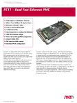
Figure 3. Installing SA-Adapters on F206 directly
Optional 10‐pin 10‐pin plug
receptacle
D‐Sub front connector
40‐pin plug
10‐pin receptacle
F206
2 M3x6 pan‐head screws according to DIN85 with washers
MEN Mikro Elektronik GmbH
20F206-00 E5 – 2012-03-21
17
Getting Started
1.4.2
Connection via Ribbon Cable (X3-X8)
MEN offers two special mounting kits for easy installation of up to six additional
SA-Adapters on the F206. They include an additional front panel with the required
number of cut-outs for D-Sub connectors and any ribbon cables needed.
Please refer to MEN’s website for ordering information.
!
Note: MEN gives no warranty on functionality and reliability of the board and SAAdapters used if you install SA-Adapters in a different way than described in
MEN’s documentation.
1.4.2.1
Installation of Three Additional SA-Adapters
Perform the following steps to install up to three additional SA-Adapters:
Make sure that the adapter matches the standard dimensions for SA-Adapters.
(See also installation hints in the adapter’s user manual or the list of compatible
accessories in the F206 data sheet on MEN’s website.)
Power-down your system and remove the F206 from the system.
Remove the blind connectors from the additional front panel if you need a cutout that is covered: Loosen the screws highlighted in the drawing.
Remove the front panel screws and the two screws on top of the mounting bolts
of the SA-Adapter.
Plug the 40-pin connector with the three prefolded ribbon cables to the 40-pin
plug of the carrier board.
Plug the suitable 10-pin connector of the ribbon cable to the respective 10-pin SAAdapter connector.
Make sure to always align the pins correctly (pin 1 is marked by a triangle on the
ribbon cable connector).
Use the front panel screws of the SA-Adapters to fasten the adapters at the additional front panel.
MEN Mikro Elektronik GmbH
20F206-00 E5 – 2012-03-21
18
Getting Started
You can now reinsert the board and the additional front panel into your system.
Make sure to fasten the SA-Adapter front panel appropriately in your enclosure!
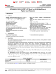
Figure 4. Installing three additional SA-Adapters via ribbon cable
Second front panel
Ribbon cable
D‐Sub front connectors
10‐pin plug
40‐pin plug
F206
2 M3x6 pan‐head screws according to DIN85 with washers
1.4.2.2
Installation of Six Additional SA-Adapters
Perform the following steps to install up to six additional SA-Adapters:
Make sure that the adapter matches the standard dimensions for SA-Adapters.
(See also installation hints in the adapter’s user manual or the list of compatible
accessories in the F206 data sheet on MEN’s website.)
Power-down your system and remove the F206 from the system.
Remove the blind connectors from the additional front panel if you need a cutout that is covered: Loosen the screws highlighted in the drawing.
Remove the front panel screws and the two screws on top of the mounting bolts
of the SA-Adapter.
MEN Mikro Elektronik GmbH
20F206-00 E5 – 2012-03-21
19
Getting Started
Plug the two prefolded ribbon cables to the 10-pin plugs of the carrier board.
Plug the 10-pin connectors of the ribbon cables to the 10-pin SA-Adapter plugs.
10‐pin plug
Plug the 40-pin connector with the four prefolded ribbon cables to the 40-pin
plug of the carrier board.
Plug the suitable 10-pin connector of the ribbon cable to the respective 10-pin SAAdapter connector.
Make sure to always align the pins correctly (pin 1 is marked by a triangle on the
ribbon cable connector).
40‐pin connector
2nd front panel slot
3rd front panel slot
Fasten the three SA-Adapters for the second front panel slot (see picture above)
to the lower three cutouts of the additional front panel using the front panel
screws of the SA-Adapters.
MEN Mikro Elektronik GmbH
20F206-00 E5 – 2012-03-21
20
Getting Started
Bend over the three SA-Adapters for the third front panel slot and fasten these
on the upper three cutouts of the additional front panel using the front panel
screws of the SA-Adapters.
You can now reinsert the board and the additional front panel into your system.
Make sure to fasten the SA-Adapter front panel appropriately in your enclosure!
Figure 5. Installing six additional SA-Adapters via ribbon cable
Second front panel
Ribbon cables
D‐Sub front connectors
40‐pin plug
F206
2 M3x6 pan‐head screws according to DIN85 with washers
MEN Mikro Elektronik GmbH
20F206-00 E5 – 2012-03-21
10‐pin plug
21
Getting Started
1.5
Integrating the Board into a System
You can use the following check list when installing the board in a system for the
first time.
Install the desired SA-Adapters on the F206. (See Chapter 1.4 Installing SAAdapters on page 16.)
Power-down the system.
Insert the F206 into a peripheral slot of your CompactPCI system, making sure
that the CompactPCI connectors are properly aligned.
Note: The peripheral slots of every CompactPCI system are marked by a circle
on the backplane and/or at the front panel.
Power-up the system.
You can now install driver software for the F206 I/O interfaces.
1.6
Installing Driver Software
For a detailed description on how to install driver software please refer to the
respective documentation.
You can find any driver software available for download on MEN’s website.
MEN Mikro Elektronik GmbH
20F206-00 E5 – 2012-03-21
22
Functional Description
2
Functional Description
2.1
Power Supply
Power supply is fed via the CompactPCI backplane. The board operates on +3.3 V
and +5 V.
2.2
UART Interfaces
The F206 offers up to eight UARTs that can be configured as a non-differential
(single-ended) RS232, or differential RS422 (full duplex) or RS485 (half duplex)
interface with full handshake support. The physical layers are defined through SAAdapters, and can be set individually for each channel through software. (See
software documentation for more details.)
MEN provides a range of standard adapters with different line interfaces, e.g.
RS232, RS422/485, or IBIS.
The UART controller is a standard IP core from MEN called 16Z025_UART
implemented in an onboard FPGA.
Please see MEN’s website for ordering information of SA-Adapters.
You can find more information in the 16Z025_UART data sheet on MEN’s website.
Please see MEN’s website for up-to-date driver software and documentation.
The register set of the octal UART is fully 16550 compatible.
MEN Mikro Elektronik GmbH
20F206-00 E5 – 2012-03-21
23
Functional Description
2.2.1
Connection
Table 1. Signal mnemonics of UART interfaces
Signal
Direction
Function
CTS
in
Clear to send
DCD
in
Data carrier detected
DSR
in
Data set ready
DTR
out
Data terminal ready
GND
-
Ground
RI
in
Ring indicator
RTS
out
Request to send
RXD
in
Receive data
TXD
out
Transmit data
+5V
in
Power supply
Note: The following pin tables give the supported standard pin-out for RS232. This
pin assignment differs depending on the SA-Adapter used, for example
RS422/485. Please refer to the user manual of the actually used SA-Adapter
for details. See Chapter 4.2 Literature and Web Resources on page 36.
2.2.1.1
Connection via 10-pin Receptacle Connectors
Table 2. Pin assignment of the 10-pin UART X1 receptacle connector
9
1
10
2
9
DCD1#
1
RI1#
7
DSR1#
8
CTS1#
5
DTR1#
6
RTS1#
3
TXD1
4
RXD1
1
GND
2
+5V
X1
Table 3. Pin assignment of the 10-pin UART X2 receptacle connector
9
1
10
2
9
DCD2#
10
RI2#
7
DSR2#
8
CTS2#
5
DTR2#
6
RTS2#
3
TXD2
4
RXD2
1
GND
2
+5V
X2
Connector types:
• 10-pin receptacle, 2.54mm pitch, for SA-Adapter connection
Mating connector:
• 10-pin SA-Adapter plug
MEN Mikro Elektronik GmbH
20F206-00 E5 – 2012-03-21
24
Functional Description
2.2.1.2
Connection via 10-pin Plug Connectors
Table 4. Pin assignment of the 10-pin UART X3 plug connector
10
2
10
RI3#
9
DCD3#
8
CTS3#
7
DSR3#
6
RTS3#
5
DTR3#
4
RXD3
3
TXD3
2
+5V
1
GND
9
1
X3
Table 5. Pin assignment of the 10-pin UART X4 plug connector
10
2
10
RI4#
9
DCD4#
8
CTS4#
7
DSR4#
6
RTS4#
4
DTR4#
4
RXD4
3
TXD4
2
+5V
1
GND
9
1
X4
Connector types:
• 10-pin plug, IDC ribbon-cable connector according to DIN41651/MIL-C-83503,
plug connector with lock
• Mating connector:
10-pin receptacle, available with or without tension relief for ribbon-cable connection, 1.27mm pitch
MEN Mikro Elektronik GmbH
20F206-00 E5 – 2012-03-21
25
Functional Description
2.2.1.3
Connection via 40-pin Plug Connector
Table 6. Pin assignment of the 40-pin UART X8, X7, X6, X5 plug connector
40
2
39
1
40
RI8#
39
DCD8#
38
CTS8#
37
DSR8#
36
RTS8#
35
DTR8#
34
RXD8
33
TXD8
32
+5V
31
GND
30
RI7#
29
DCD7#
28
CTS7#
27
DSR7#
26
RTS7#
25
DTR7#
24
RXD7
27
TXD7
22
+5V
21
GND
20
RI6#
19
DCD6#
18
CTS6#
16
DSR6#
16
RTS6#
6
DTR6#
14
RXD6
13
TXD6
12
+5V
11
GND
10
RI#5
9
DCD#5
8
CTS#5
7
DSR#5
6
RTS#5
5
DTR#5
4
RXD5
3
TXD5
2
+5V
1
GND
X8
X7
X6
X5
Connector types:
• 40-pin low-profile plug, 2.54mm pitch, for ribbon-cable connection
• Mating connector:
40-pin IDC receptacle, e.g. Elco Series 8290 IDC socket
MEN Mikro Elektronik GmbH
20F206-00 E5 – 2012-03-21
26
Functional Description
2.2.2
Setting the Physical Layer
The UART channels can be configured individually as differential RS422 or RS485,
or non-differential (single-ended) RS232 interfaces. The setting is made using driver
software. For Windows MEN offers a driver installation package that allows easy
configuration through the Device Manager. For Linux, VxWorks and QNX MEN
also offers driver software that provides the necessary functions to write application
software.
The following chapters give hints on how to make settings under the supported
operating systems.
For further details on the different driver packages, please refer to the respective
software documentation.
Please see MEN’s website for up-to-date driver software and documentation.
2.2.2.1
Configuration under Windows
MEN’s driver installation package (Installset) for Windows allows easy
configuration through the Device Manager.
To do this, open the Properties page of each F206 UART device via the Windows
Device Manager, select the Port Interface tab and choose the used physical
interface.
You can find more details on the Windows Installset in the F206 Windows Installset User Manual.
You can download the Windows driver and user manual from MEN’s website.
2.2.2.2
Configuration under Linux
MEN provides a Linux driver that allows to configure the interface mode and baud
rate.
You can download the Linux driver and documentation from MEN’s website.
The baud_base parameter must be set to 115200.
MEN’s Linux driver supports the following values for the mode parameter:
se
single ended (RS232)
df_fdx
differential, full duplex (RS422)
df_hdxe
differential, half duplex, with echo (RS485)
df_hdx
differential, half duplex, no echo (RS485)
MEN Mikro Elektronik GmbH
20F206-00 E5 – 2012-03-21
27
Functional Description
The following examples show how to use the driver with F206.
Set all UART ports to RS232 mode
# modprobe men_lx_chameleon usePciIrq=1
# modprobe men_lx_is baud_base=115200 mode=se,se,se,se,se,se,se,se,se
Set all UART ports to RS422 full-duplex mode
In order to change the settings, the driver needs to be removed first.
# rmmod men_lx_frodo
# modprobe men_lx_frodo baud_base=115200
mode=df_fdx,df_fdx,df_fdx,df_fdx,df_fdx,df_fdx,df_fdx,df_fdx,df_fdx
!
Note: Most Linux kernels only support 4 UARTs by default. If you need more than
4 UARTs, add parameter 8250.nr_uarts=48 to your kernel boot line in the
bootloader or adjust kernel parameter CONFIG_NR_8250_UARTS and
recompile the kernel.
2.2.2.3
Configuration under VxWorks
MEN provides a VxWorks driver that provides comprehensive I/O control support
to configure the interfaces.
You can find more details on MEN’s VxWorks driver software in the driver’s
included HTML documentation.
You can download the VxWorks driver from MEN’s website.
The UART clock frequency must be set to 1843200. You can use driver function
Z25_CreateDevice or Z25_SetBaseBaud to do this.
2.2.2.4
Configuration under QNX
MEN provides a QNX driver that allows configuration of the interfaces through
QNX tool stty.
The stty tool together with MEN’s QNX driver provides a large number of
parameters to configure serial interfaces. MEN’s driver includes options to set the
physical interface itself. You can get details on the driver using QNX command use
devc-serz025.
You can download the QNX driver from MEN’s website.
To get details on the driver use QNX command use devc-serz025.
You can find more information on stty also on the QNX developer community website.
MEN Mikro Elektronik GmbH
20F206-00 E5 – 2012-03-21
28
Functional Description
2.3
Front-Panel LEDs
The F206 is equipped with four user LEDs which are controlled by the LED Control
Register (LEDCR) of the FPGA. See Chapter 3.2.2.3 Registers on page 34 for more
information.
Once the F206 has successfully loaded its FPGA content, the red LED (#1) is
flashing. This is the default setting, which can also be configured by software (see
also Chapter 3.2.2.3 Registers on page 34).
Table 7. Front-panel LEDs
LED No. / Color
1 2 3 4
2.4
Function
1 - red
User LED, controlled through bit 0 of the LEDCR
2 - yellow
User LED, controlled through bit 1 of the LEDCR
3 - yellow
User LED, controlled through bit 2 of the LEDCR
4 - green
User LED, controlled through bit 3 of the LEDCR
CompactPCI Interface
The F206 supports a 32-bit 33-MHz CompactPCI interface fully compatible with
CompactPCI specification PICMG 2.0 Rev. 3.0. The board works with 3.3 V VI/O.
For full CompactPCI functionality only the J1 connector is needed, therefore the
board only has a J1 connector to the bus.
Connector type of J1:
• 110-pin shielded, 2mm-pitch, 5-row receptacle according to IEC 917 and IEC
1076-4-101
The pin assignment of connector J1 as defined in the CompactPCI specification will
not be repeated here.
MEN Mikro Elektronik GmbH
20F206-00 E5 – 2012-03-21
29
FPGA
3
FPGA
3.1
General
The FPGA – as a part of the F206 – represents an interface between a userselectable configuration of I/O modules (IP cores) and the PCI bus. The PCI core
included in the FPGA can be a PCI target or master. It can be accessed via memory
single/burst read/write cycles.
The Wishbone bus is the uniform interface where IP cores can be connected in
addition to the System Unit to provide the highest possible flexibility for different
configurations of the FPGA.
Each implementation contains a bridge from the PCI bus to the Wishbone bus.
Additionally each implementation contains a system unit for system-specific
functions such as reset/interrupt control or watchdog etc. and the system library. The
presence of the single system unit functions (and system registers) depends on the
necessity in the actual implementation and cannot be described in general.
Figure 6. FPGA – Block diagram
PCI bus
FPGA
PCI
Master
PCI‐to‐
Wishbone Bridge
PCI
Slave
FPGA IP Core 1
System Unit
I/O signals
FPGA IP Core 2
...
I/O signals
FPGA IP Core n
...
I/O signals
Wishbone Interconnection
The FPGA System Unit contains a configuration table providing the information
which modules are implemented (device number) in the current configuration.
Furthermore the revision, the instance number (one module can be instantiated more
than one time), the interrupt routing and the base address of the module are stored.
At initialization time, the CPU has to read the configuration table to get the
information of the base addresses of the included modules.
Note that with regard to the FPGA resources such as available logic elements or pins
it is not possible to grant all possible combinations of the FPGA IP cores. Chapter
3.3 Standard Factory FPGA Configuration on page 35 describes one possible
configuration of the FPGA. Please ask our sales staff for other configurations.
MEN Mikro Elektronik GmbH
20F206-00 E5 – 2012-03-21
30
FPGA
3.2
System Unit
The system unit is available in all configurations and contains a number of modules
with system functionality communicating with the CPU.
3.2.1
Functional Description
3.2.1.1
Interrupt Controller
The interrupt controller combines the interrupt requests of all implemented
modules, one interrupt line for one module. The system registers are consolidated to
one module, therefore interrupt line 0 is reserved for the system register unit. Since
the interrupt controller handles 16 interrupt requests, 15 IP cores can request an
interrupt without sharing.
The interrupt requests are stored in a 16-bit Interrupt Request Register (IRQR).
There is one PCI interrupt line for all interrupt requests. All used interrupt requests
are ORed to this interrupt line. Any module's interrupt request can be enabled or
disabled only in the module which generates the interrupt by writing 1 or 0 to the
corresponding bit of the module's interrupt enable register.
MEN Mikro Elektronik GmbH
20F206-00 E5 – 2012-03-21
31
FPGA
3.2.2
Address Organization
3.2.2.1
Address Map
Table 8. FPGA – Address map
Address
D15..D0
0x0000
Identification Word (IW) (r)
0x0004
Magic Word (MW) (r)
0x0008
Configuration Table (CT) (r)
0x0080
Interrupt Request Register (IRQR) (r)
0x009C
General Purpose Memory Register (GPMR) (r/w)
0x00A0
LED Control Register (LEDCR) (r/w)
0x00A4..0x00FF Reserved
0x0100..0x1FFF FPGA IP cores (see detailed address map in the respective
IP core user manual)
MEN Mikro Elektronik GmbH
20F206-00 E5 – 2012-03-21
32
FPGA
3.2.2.2
Identification Word and Configuration Table
The address space of the FPGA starts with an identification word and a
configuration table. The identification word (BAR0; address 0x0000) describes the
FPGA configuration by a character (A to Z) and its revision number. Byte 0 at
address 0x0000 contains the revision number, byte 1 at address 0x0001 contains
the describing character in ASCII format.
Example: address 0x0000 identification word 0x4103 variant A3
In the FPGA address space the identification word is followed by the configuration
table which gives detailed information about the implemented modules.
The Magic Word at address 0x0004 is used by software to identify the
configuration table.
It is possible to use different Base Address Registers of the PCI Configuration
Space. (This is necessary for modules which require an address space larger than
256 bytes.) If other BARs are used, the module's memory space which is allocated
with the BARs other than BAR 0 has other base addresses as viewed from the PCI
bus. Inside the board’s FPGA the module's address space starts at 0x0000 too, but
all modules are enabled by a chip select signal generated in consideration of the
used BAR.
A separate Base Address Register (apart from BAR 0) can be used e.g. to access
memory. This simplifies PCI host accesses to that module because the memory's
address always starts at 0x0000. The PCI host must access the FPGA with the
correct base address only.
To provide the information which modules are implemented, the FPGA
configuration table contains two binary words for each module to code module
information such as
•
•
•
•
•
•
Device
Revision
Used Base Address Register
Number of instance
Used interrupt line for that device
Start address in F206 memory space
You can find an overview and descriptions of all available FPGA IP cores on MEN’s
website.
Chapter 3.3 Standard Factory FPGA Configuration on page 35 gives an example
configuration, including a configuration table.
MEN Mikro Elektronik GmbH
20F206-00 E5 – 2012-03-21
33
FPGA
3.2.2.3
Registers
Interrupt Request Register IRQR (0x0080) (read only)
The read-only Interrupt Request Register IRQR provides information about the
interrupt source that has generated an interrupt. Each implemented module supplies
one Interrupt Request Register bit. The configuration table gives the information
about the interrupt routing to show which module corresponds to which IRQR bit.
15
14
13
12
11
10
9
8
7
6
5
4
3
2
1
0
Irqn Irqn Irqn Irqn Irqn Irqn Irqn Irqn Irqn Irqn Irqn Irqn Irqn Irqn Irqn Irqn
S15 S14 S13 S12 S11 S10 S9 S8 S7 S6 S5 S4 S3 S2 S1 S0
Reset value: 0xFFFF
IrqnSx
0 = Pending interrupt of source (module) x
1 = No interrupt of source (module) x is pending
General Purpose Memory Register GPMR (0x009C) (read/write)
The GPMR is an 8-bit register that the programmer can use to store data which will
not be changed during a reset phase. The register can be read from and written to by
the programmer. Only power on resets the register to its initial value.
15..8
7..0
Reserved for future use
GPMR
Reset value: 0x0000
LED Control Register LEDCR (0x00A0) (read/write)
The LED Control Register allows to switch on or off four LEDs (as supported by
carrier board) by setting the corresponding register bit to 0 (on) or 1 (off). After
power-on and after reset LED0 is set to 0, which means in normal mode that the
LED is switched on. After power-on and after reset, this LED is used for diagnosis
and is toggled by the System Unit until a value was written to bit LED0. After this
procedure, LED0 can be used in a normal way.
15..4
Reserved for future use
3
2
1
0
LED3 LED2 LED1 LED0
Reset value: 0x000E
LEDx
MEN Mikro Elektronik GmbH
20F206-00 E5 – 2012-03-21
0 = LED is on
1 = LED is off
34
FPGA
3.3
Standard Factory FPGA Configuration
3.3.1
IP Cores
The factory FPGA configuration for standard boards comprises the following FPGA
IP cores:
•
•
•
•
•
Main bus interface
16Z054_SYSTEM – System unit
16Z025_UART – UART controller (controls four UARTs)
16Z025_UART – UART controller (controls four UARTs)
16Z045_FLASH – Flash Interface
3.3.2
FPGA Configuration Table
The resulting configuration table of the standard FPGA is as follows:
Table 9. FPGA – Factory standard configuration table for F206
IP Core
16Z054_SYSTEM
16Z025_UART
16Z025_UART
16Z045_FLASH
Magic Word
Variant
Revision
MEN Mikro Elektronik GmbH
20F206-00 E5 – 2012-03-21
Device ID
36
19
19
2D
Revision
ABCD
B
3
IRQ
1
B
B
1
BAR
0
1
2
3
Offset
0
0
0
0
0
100
200
300
All values are given in
hexadecimal notation.
35
Appendix
4
Appendix
4.1
PCI Configuration
The F206 has the following IDs on the PCI bus:
•
•
•
•
PCI Device ID: 0x000B
PCI Vendor ID: 0x1172
Subsystem Device ID: 0x5A14
Subsystem Vendor ID: 0x4D45
4.2
Literature and Web Resources
• F206 data sheet with up-to-date information and documentation:
www.men.de/products/02F206-.html
• MEN SA-Adapters:
www.men.de/products/search,SA--Adapters,accessories.1.html
4.2.1
CompactPCI
• CompactPCI Specification PICMG 2.0 R3.0:
1999; PCI Industrial Computers Manufacturers Group (PICMG)
www.picmg.org
• PCI Local Bus Specification Revision 2.2:
1995; PCI Special Interest Group
P.O. Box 14070
Portland, OR 97214, USA
www.pcisig.com
MEN Mikro Elektronik GmbH
20F206-00 E5 – 2012-03-21
36
Appendix
4.3
Finding out the Board’s Article Number, Revision and
Serial Number
MEN user documentation may describe several different models and/or hardware
revisions of the F206. You can find information on the article number, the board
revision and the serial number on two labels attached to the board.
• Article number: Gives the board’s family and model. This is also MEN’s ordering number. To be complete it must have 9 characters.
• Revision number: Gives the hardware revision of the board.
• Serial number: Unique identification assigned during production.
If you need support, you should communicate these numbers to MEN.
Figure 7. Labels giving the board’s article number, revision and serial number
Complete article number
02F206-00
00.00.00
Revision number
Serial number
MEN Mikro Elektronik GmbH
20F206-00 E5 – 2012-03-21
37