1
AN10255
Philips LPC210x microcontroller family
Rev. 02 — 25 October 2004
Application note
Document information
Info
Content
Keywords
LPC210x, JTAG
Abstract
This application note demonstrates how to use the LPC210x secondary
JTAG interface while debugging the user application. The secondary
JTAG interface provides the customer with 10 additional port pins, which
would otherwise be allocated to the Embedded Trace Macrocell (ETM).
The secondary JTAG interface can be used if the application only needs
JTAG support for debugging.
AN10255
Philips Semiconductors
Philips LPC210x microcontroller family
Revision history
Rev
Date
02
20041025
01
20040107
Description
•
The format of this application note has been redesigned to comply with the new
presentation and information standard of Philips Semiconductors
•
Interrupt handling code was updated. In the earlier version, the interrupt vector setup
was incorrect.
•
Using secondary JTAG interface for debugging the application from Flash has been
added.
•
More comprehensive information on DBGSEL and RTCK was added.
Initial version
9397 750 14066
Application note
© Koninklijke Philips Electronics N.V. 2004. All rights reserved.
Rev. 02 — 25 October 2004
2 of 10
AN10255
Philips Semiconductors
Philips LPC210x microcontroller family
1. Introduction
Before examining the secondary JTAG let’s take a look at the LPC210x debug mode. The
Debug Select (DBGSEL) and Returned Test Clock Output (RTCK) pins are used to enter
the debug mode (primary JTAG and ETM). If DBGSEL is configured high (on or after
reset) and if RTCK is latched high on reset then pins P0[17:31] are configured as debug
pins. The ARM7TDMI-S Debug Architecture uses the JTAG port along with the
EmbeddedICE debug logic to provide on-chip debug support.
When JTAG and ETM are enabled, port pins P0[17:31] are not usable by the application.
The Primary JTAG interface uses pins P0[17:21] and pins P0[22:31] are used by the ETM
(Embedded Trace Macrocell). The user may wish to debug the application using Primary
JTAG only, but even then the bottom 10 port pins are not usable by the application.
The secondary JTAG interface is provided to free the ETM pins for use as port pins when
debug with trace is not required. Under this interface user can debug the application and
can have 10 additional port pins for the application, which would otherwise be used by the
ETM. However, in this case the port pins used by the secondary JTAG interface will be
pins P0[27:31], which implies that all the remaining port pins from P0[0:26] are usable by
the application.
2. How to configure the secondary JTAG in LPC210x
2.1 Debugging the application from SRAM
For configuring the secondary JTAG interface, the user needs to run a simple application
from Flash on reset. If at least one of the DBGSEL or RTCK lines is low on reset then
neither primary JTAG nor ETM pins are enabled. The code should map port pins
(P0[27:31]) to alternate function 1, which is the secondary JTAG interface (Please refer to
the Pin Configuration and Pin Connect Block chapters in the LPC2106/2105/2104 User
Manual where the port pins P0[27:31] are shown to be configurable to alternate
function1). Since this application runs after reset the user can’t switch to secondary JTAG
in the same debug session.
Steps on how to switch to secondary JTAG are as follows:
1. Load the application in Flash using the software debugger and the primary JTAG
interface. This application could also be loaded using an ISP utility (provided by some
of our tool partners or by Philips itself)
2. Close the debugger or ISP utility (be sure to disconnect P.14 from ground)
3. Drive DBGSEL and/or RTCK low and connect port pins P0[27:31] to the JTAG port (If
your evaluation board supports the secondary JTAG interface then there should be a
jumper that does the above)
4. Reset the part.
5. If the correct signature resides at 0x14 (More information in the Flash Memory System
and Programming chapter in the LPC2106/2105/2104 User Manual) then user
application in Flash will run and the port pins P0[27:31] will be configured to
secondary JTAG. The Philips Flash-programming tool and most of the debuggers
handle the signature generation automatically.
9397 750 14066
Application note
© Koninklijke Philips Electronics N.V. 2004. All rights reserved.
Rev. 02 — 25 October 2004
3 of 10
AN10255
Philips Semiconductors
Philips LPC210x microcontroller family
6. User should then be able to debug the application using the secondary JTAG
interface.
2.2 Debugging the application from Flash
If the application needs to be debugged from Flash then the secondary JTAG application
needs to be added to the end-user’s application code. The code should be linked in such
a way that the secondary JTAG application runs first and this should be followed by main
end-user application code.
The steps for configuring the interface for debugging out of Flash remain the same as
above. After performing steps 1, 2, 3 and 4 (reset) the main application may run until the
end user could connect the debugger to the JTAG port. That is not a problem since once
connected to the Secondary JTAG interface one could start the debugging process all
over again. To avoid this situation, after the Pin Select register is written to there could be
a delay routine before running the main application which will give the end-user sufficient
time to connect the debugger.
2.2.1 Software Example for configuring secondary JTAG
The application that runs from Flash at reset is provided in assembly and C. Since the
interrupt vectors for ARM lie at 0x00-0x1C, this code must be linked to memory location
0x0. After the interrupt vectors, a few instructions are listed where the secondary JTAG
interface is configured. The code has been developed in the ARM Development Suite
(ADS) v1.2.
2.2.1.1
Assembly code
; --------------------------------------------------------;
Assembler Directives
; --------------------------------------------------------AREA IVT, CODE ; New Code section
CODE32 ; ARM code
entry
; --------------------------------------------------------LDR
PC, =start
LDR
PC, Undefined_Addr
LDR
PC, SWI_Addr
LDR
PC, Prefetch_Addr
LDR
PC, Abort_Addr
;
;
;
;
;
;
;
;
;
;
At 0x14 the user should insert a signature (checksum).
This signature enables the bootloader to determine if
there is valid user code in the Flash. Currently most of
the Flash programming tools (debuggers and ISP utility)
have this feature built-in so the end user need not worry
about it. If the tool does not provide this feature then
the value has to be computed manually and has to be
inserted at 0x14. Details on computation of checksum
could be found in the Flash programming chapter in the
LPC2106/2105/2104 User Manual.
DCD } .
9397 750 14066
Application note
© Koninklijke Philips Electronics N.V. 2004. All rights reserved.
Rev. 02 — 25 October 2004
4 of 10
AN10255
Philips Semiconductors
Philips LPC210x microcontroller family
LDR
LDR
PC, IRQ_Addr
PC, FIQ_Addr
Undefined_Addr
SWI_Addr
Prefetch_Addr
Abort_Addr
IRQ_Addr DCD
FIQ_Addr
DCD
Undefined_Handler
DCD
SWI_Handler
DCD
Prefetch_Handler
DCD
Abort_Handler
IRQ_Handler
DCD
FIQ_Handler
; --------------------------------------------------------;
Exception Handlers
; --------------------------------------------------------; The following dummy handlers do not do anything useful in
; this example. They are set up here for completeness.
Undefined_Handler
B
Undefined_Handler
SWI_Handler
B
SWI_Handler
Prefetch_Handler
B
Prefetch_Handler
Abort_Handler
B
Abort_Handler
IRQ_Handler
B
IRQ_Handler
FIQ_Handler
B
FIQ_Handler
;---------------------------------------------------------; Main code
;---------------------------------------------------------start
LDR SP=0x4 }}
; Set the Stack pointer for
; the Supervisor mode
LDR R0, JTAG2
; Load R0 with 0x55400000
LDR R1, PINSEL1 ; Load R1 with 0xE002C004
STR R0, [R1]
; Load PINSEL1 with 0x55400000
Always
B Always
; Stay here if application to
; be debugged resides in
; SRAM else should be
; followed by the
; application(or jump to
; application) if it needs to
; be debugged from Flash(see
; below) after an optional
; delay routine
;---------------------------------------------------------9397 750 14066
Application note
© Koninklijke Philips Electronics N.V. 2004. All rights reserved.
Rev. 02 — 25 October 2004
5 of 10
AN10255
Philips Semiconductors
Philips LPC210x microcontroller family
; Allocate words in memory and assign values
;---------------------------------------------------------JTAG2
DCD 0x55400000
PINSEL1
DCD 0xE002C004
END
The user may have to modify the assembler directives depending upon the assembler
being used. The function of the exception vectors here is to provide the signature for the
bootloader at memory location 0x14, which enables the bootloader to detect, that there is
valid user code in the Flash memory.
On reset the first instruction to be executed would be
LDR
PC, =start
which would branch to symbol start where SFR Pin Function Select Register 1 (Refer to
Pin Connect block section in the LPC2106/2105/2104 User Manual) is loaded with
0x55400000. Port pins P0[27:31] are now configured for alternate function 1(secondary
JTAG pins).
After loading this application into Flash and then performing the steps mentioned above,
the debugger must be able to talk via the secondary JTAG interface.
2.2.1.2
C code (Interrupt Vector Table in assembly)
The code has been developed in the ARM Development Suite (ADS) v1.2. Only the
relevant files are mentioned here, tool specific files are excluded. The code remains very
much the same as above except that the main section where the secondary JTAG
interface is configured is now written within C main (). The assembly code should reside
from 0x0. The C file could be linked immediately after the interrupt vectors.
Interrupt Vector Table:
; --------------------------------------------------------;
Assembler Directives
; --------------------------------------------------------AREA IVT, CODE
; New Code section
CODE32
; ARM code
IMPORT __main
; symbol main not
; defined in this
; section
entry
; --------------------------------------------------------LDR PC, =start ; jump to start
LDR PC, Undefined_Addr
LDR PC, SWI_Addr
LDR PC, Prefetch_Addr
LDR PC, Abort_Addr
; At 0x14 the user should insert a signature (checksum).
; This signature enables the bootloader to determine if
; there is valid user code in the Flash. Currently most of
9397 750 14066
Application note
© Koninklijke Philips Electronics N.V. 2004. All rights reserved.
Rev. 02 — 25 October 2004
6 of 10
AN10255
Philips Semiconductors
Philips LPC210x microcontroller family
;
;
;
;
;
;
;
the Flash programming tools (debuggers and ISP utility)
have this feature built-in so the end user need not worry
about it. If the tool does not provide this feature then
the value has to be computed manually and has to be
inserted at 0x14. Details on computation of checksum
could be found in the Flash programming chapter in the
LPC2106/2105/2104 User Manual.
DCD } .
LDR PC, IRQ_Addr
LDR PC, FIQ_Addr
Undefined_Addr
SWI_Addr
Prefetch_Addr
Abort_Addr
IRQ_Addr
FIQ_Addr
DCD
DCD
DCD
DCD
DCD
DCD
Undefined_Handler
SWI_Handler
Prefetch_Handler
Abort_Handler
IRQ_Handler
FIQ_Handler
; --------------------------------------------------------;
Exception Handlers
; --------------------------------------------------------; The following dummy handlers do not do anything useful in this example. They are
set up here for completeness.
Undefined_Handler
B
Undefined_Handler
SWI_Handler
B
SWI_Handler
Prefetch_Handler
B
Prefetch_Handler
Abort_Handler
B
Abort_Handler
IRQ_Handler
B
IRQ_Handler
FIQ_Handler
B
FIQ_Handler
;---------------------------------------------------------; Linked from the first instruction
;---------------------------------------------------------start
LDR SP,=0x4 } .. ; Setting up SP for SVC mode
LDR LR,=__main ; Jump to C main()
MOV PC,LR
END
C code:
#define PINSEL1 (*((volatile unsigned int *)0xE002C004))
9397 750 14066
Application note
© Koninklijke Philips Electronics N.V. 2004. All rights reserved.
Rev. 02 — 25 October 2004
7 of 10
AN10255
Philips Semiconductors
Philips LPC210x microcontroller family
int main()
{
PINSEL1=0x55400000; // Configure Pins P0[27:31] // to alternate function 1
// which sets up the
// secondary JTAG
// Should be replaced by main application (or jump to // main application) after an
optional delay routine // if application needs to be debugged from Flash
while(1){}
}
2.3 Concluding statements
Combination of (DBGSEL+ RTCK) pins takes LPC210x into debug mode and configures
port pins P0[17:31] as debug pins. If you wish to debug only through JTAG use the
secondary JTAG interface (Port pins P0[27:31]) by running a simple application from
Flash and by driving either or both DBGSEL and/or RTCK low. Hardware support is
needed to use the secondary JTAG interface.
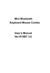
Table 1 summarizes the debug pins configuration.
Table 1:
Debug pins configuration
DBGSEL (On or
after reset)
RTCK (latched
on reset)
JTAG primary
pins
JTAG Secondary ETM
pins
1
1
Yes
No
No
0
1
No
SW
1
0
No
SW config[1]
No
0
0
No
SW config[1]
No
[1]
Start-up-code residing in Flash should configure port pins P0[27:31] for JTAG function by setting
appropriate bits in PINSEL1 register.
9397 750 14066
Application note
Yes
config[1]
© Koninklijke Philips Electronics N.V. 2004. All rights reserved.
Rev. 02 — 25 October 2004
8 of 10
AN10255
Philips Semiconductors
Philips LPC210x microcontroller family
3. Disclaimers
Life support — These products are not designed for use in life support
appliances, devices, or systems where malfunction of these products can
reasonably be expected to result in personal injury. Philips Semiconductors
customers using or selling these products for use in such applications do so
at their own risk and agree to fully indemnify Philips Semiconductors for any
damages resulting from such application.
Right to make changes — Philips Semiconductors reserves the right to
make changes in the products - including circuits, standard cells, and/or
software - described or contained herein in order to improve design and/or
performance. When the product is in full production (status ‘Production’),
relevant changes will be communicated via a Customer Product/Process
Change Notification (CPCN). Philips Semiconductors assumes no
responsibility or liability for the use of any of these products, conveys no
licence or title under any patent, copyright, or mask work right to these
products, and makes no representations or warranties that these products are
free from patent, copyright, or mask work right infringement, unless otherwise
specified.
Application information — Applications that are described herein for any
of these products are for illustrative purposes only. Philips Semiconductors
make no representation or warranty that such applications will be suitable for
the specified use without further testing or modification.
9397 750 14066
Application note
© Koninklijke Philips Electronics N.V. 2004. All rights reserved.
Rev. 02 — 25 October 2004
9 of 10
AN10255
Philips Semiconductors
Philips LPC210x microcontroller family
4. Contents
1
2
Introduction . . . . . . . . . . . . . . . . . . . . . . . . . . . .
How to configure the secondary JTAG in
LPC210x . . . . . . . . . . . . . . . . . . . . . . . . . . . . . . .
2.1
Debugging the application from SRAM. . . . . . .
2.2
Debugging the application from Flash . . . . . . .
2.2.1
Software Example for configuring secondary
JTAG. . . . . . . . . . . . . . . . . . . . . . . . . . . . . . . . .
2.2.1.1
Assembly code . . . . . . . . . . . . . . . . . . . . . . . . .
2.2.1.2
C code (Interrupt Vector Table in assembly). . .
2.3
Concluding statements . . . . . . . . . . . . . . . . . . .
3
Disclaimers. . . . . . . . . . . . . . . . . . . . . . . . . . . . .
3
3
3
4
4
4
6
8
9
© Koninklijke Philips Electronics N.V. 2004
All rights are reserved. Reproduction in whole or in part is prohibited without the prior
written consent of the copyright owner. The information presented in this document does
not form part of any quotation or contract, is believed to be accurate and reliable and may
be changed without notice. No liability will be accepted by the publisher for any
consequence of its use. Publication thereof does not convey nor imply any license under
patent- or other industrial or intellectual property rights.
Date of release: 25 October 2004
Document number: 9397 750 14066
Published in The U.S.A.