1
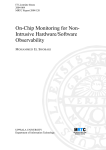
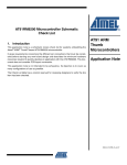
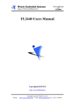
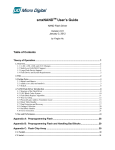
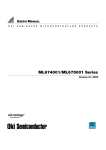
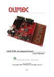
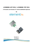
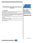
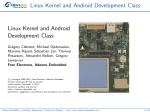
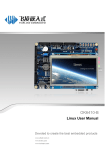
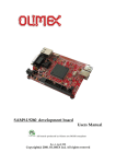
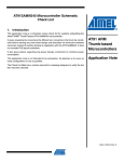
Users Manual
Copyright@2010-2011
http://www.arm9board.net
Copyright reserved© Witech Co., Ltd.
Website: http://www.arm9board.net Email: [email protected] Tel: +86-871-5899845
COPYRIGHT STATEMENT
Contents (content being images, text, programs and scripts)
of this manual is copyright © Witech Systems Ltd. All rights
expressly reserved.
Any content of the manual printed or downloaded may not be
sold, licensed, transferred, copied or reproduced in whole or in part
in any manner or in or on any media to any person without the prior
written consent of Witech Systems Ltd. including but not limited to:
z transmission by any method
z storage in any medium, system or program
z display in any form
z performance
z hire, lease, rental or loan
Requests for permission to reproduce material from this manual
should be addressed to Witech Systems Ltd.
Copyright reserved© Witech Co., Ltd.
Website: http://www.arm9board.net Email: [email protected] Tel: +86-871-5899845
The TE9263 is an ARM9 Embedded SBC based on the Atmel AT91SAM9263
microcontroller. TE9263 SBC consists of a 6-layer core board and a 4-layer base board, such
structure not only makes the TE9263 more flexible but also brings the SBC much more stable and
reliable performance. Together with the TE9263 we provide BSPs (Board Support Packages) for
Embedded Linux and WindowsCE including basic drivers for all the components on the board and
illustrating programs, which we believe can help the users in understanding the ARM architecture
and shortening their development circle.
Here are some dos and don’ts for using the TE9263:
1. After opening the TE9263 package, please check and make sure that the following
components are all enclosed:
2.
3.
4.
5.
6.
z 1 × TE9263 board
z 1 × serial port cable
z 1 × USB cable
z 1 × Ethernet cable
z 1 × 5V power supply
z 1 × DVD
z (Any other optional components that you ordered)
After purchasing the TE9263, please do inform us with your purchase information,
including your name, registered email address, purchase date, invoice number and
board ID to validate your membership for downloading the latest data from our website.
When using the SBC for the first time, please do read and follow the user manual to
prevent unnecessary troubles and damages.
Every time before powering on the SBC, please touch anyone of the metallic interface
with your fingers to unload the Electrostatic. Do not touch the chips with your fingers!
Before physically operating the SBC, please switch the power off. Hot plugging is not
supported except on the USB and Ethernet interfaces.
We provide for the TE9263 12 weeks’ guarantee (in the precondition of non-artificial
damage) and 24 weeks technical support.
Editor: Witech Co. Ltd.
Tel: 86-871-5899845
Fax: 86-871-5899845
Email: [email protected]
Website: http://www.arm9board.net/
Copyright reserved© Witech Co., Ltd.
Website: http://www.arm9board.net Email: [email protected] Tel: +86-871-5899845
Chapter One: Introduction
The TE9263 Single Board Computer consists of a 6-layer core board and a 4-layer base board.
Layout and wiring on the TE9263 is meticulously designed by professionals to ensure stable
performance, which, together with a variety of interfaces, connectors, and peripherals such as
Ethernet card, sound card, CAN bus, Camera, SD card, VGA/TV output, makes the TE9263 a
reliable device for the development of medical devices, mobile devices, GPS devices, hand-held
device, consumer electronics and Industrial control equipment.
Components in the Package
Standard Components:
1. 1 × TE9263 board
2. 1 × serial port cable
3. 1 × USB cable
4. 1 × Ethernet cable
5. 1 × 5V power adapter
6. 1 × DVD
Optional Components:
1. 3.5” TFT LCD with touch panel and stylus.
2. 5.6” TFT LCD with touch panel and stylus.
3. 7” TFT LCD with touch panel and stylus.
4. 8” TFT LCD with touch panel and stylus.
5. OV9650 CMOS camera
6. USB camera
7. WIFI module
Hardware Connection
a) Connect the 5V power adapter to the power socket on the TE9263
b) Connect the COM1 to the PC serial port via the Serial cable.
c) Connect the USB Device interface to a USB port on the PC via USB cable;
d) Connect the Ethernet port to the PC via the crossover Ethernet cable;
e) Connect the LCD (if any) to the LCD interface on the TE9263, and set the Jumper J2
(LCD power voltage selector)
f) Connect the Audio output interface to a speaker
Copyright reserved© Witech Co., Ltd.
Website: http://www.arm9board.net Email: [email protected] Tel: +86-871-5899845
1. Introduction
1.1 AT91SAM9263
The AT91SAM9263 microcontroller-based system-on-chip embeds a 200 MIPS ARM926EJS-based processor. Its parallel bus architecture incorporating distributed DMA overcomes the
bottlenecks that occur with conventional ARM9-based MCUs in graphically-interfaced, dataintensive applications such as networked medical monitoring equipment and GPS navigation
systems. The AT91SAM9263 employs 27 DMA channels including Atmel’s 20-channel peripheral
DMA controller (PDC), a 9-layer bus matrix, and two additional busses for data- and instructiontightly-coupled-memories (TCMs) to boost CPU performance and provide on-chip data transfer
rates of up to 41.6 Gbps. Two external bus interfaces (EBIs) support gigabyte-plus external
memories.
On-chip human interface peripherals include a camera interface, TFT/STN LCD controller, a
6-channel audio front-end interface (AC97), I2S and a 2D graphics co-processor that off-loads line
draw, block transfer, polygon fill, and clipping functions from the CPU. Networking peripherals
include a 12 Mbps USB host and device, a 10/100 Ethernet MAC and a 1 Mbps control area
network (CAN). There are also four USARTs, two 50 Mbps serial peripheral interfaces (SPI),
CompactFlash, SDIO (MCI) and a two-wire interface (TWI) which can be connected to external
wired and wireless communication modules like GPRS modem and Wi-Fi.
Networking and Communications. Networking peripherals include a 12 Mbps USB host and
device, a 10/100 Ethernet MAC and a 1 Mbps control area network (CAN). There are also four
USARTs, two 50 Mbps serial parallel interfaces (SPI), CompactFlash®, SDIO (MCI) and a twowire interface (TWI) which can be connected to external wired and wireless communication
modules like GPRS modem and Wi-Fi®.
Peripheral DMA Controller Relieves CPU of Peripheral-to-Memory Transfers – Conventional
ARM9-based processors use load/store instructions that require at least 80 CPU cycles to transfer
a single byte of data between memory and a peripheral. Running at 200 MHz with a bus frequency
of 100 MHz, these processors typically reach the limit of their capability at about 20 Mbps even
Copyright reserved© Witech Co., Ltd.
Website: http://www.arm9board.net Email: [email protected] Tel: +86-871-5899845
with the memory management unit and instruction- and data-cache controllers enabled.
Atmel's AT91SAM9263 integrates 18 simple, silicon-efficient, single-cycle, peripheral DMA
controllers (PDC), five DMA controllers with burst mode support to the USB host, Ethernet MAC,
camera interface, LCD controller and 2D graphics controller, plus a memory-to-memory DMA
controller with burst mode, scatter-gather and linked lists support. The DMA controllers
completely off-load the execution of data transfers between external serial interfaces and
memories. At a 20 Mbps data rate, Atmel's SAM9263 still has 88% of its MIPS available for
application execution.
Eleven-layer Bus plus 96 kBytes on-chip SRAM Eliminates Bandwidth Bottlenecks. Atmel
has implemented 11 busses and 96 Kbytes of on-chip scratchpad SRAM on the AT92SAM9263.
The SRAM can be partly configured as tightly-coupled data and instruction memory (TCM). The
busses provide multiple parallel on-chip data transfer channels and a total on-chip bandwidth of
41.6 Gbps.
Dual EBI Allows Simultaneous, Parallel Operation of the ARM9 CPU and Graphics
Processors. The AT91SAM9263 has two external bus interfaces (EBI): one for the system memory
and one for the human interface. The second EBI eliminates the need for the LCD controller and
CPU to share memory and can increase available CPU MIPS by 20% to 40%.
Features
• Incorporates the ARM926EJ-S™ ARM® Thumb® Processor
– DSP instruction Extensions, Jazelle® Technology for Java® Acceleration
– 16 Kbyte Data Cache, 16 Kbyte Instruction Cache, Write Buffer
– 220 MIPS at 200 MHz
– Memory Management Unit
– EmbeddedICE™, Debug Communication Channel Support
– Mid-level Implementation Embedded Trace Macrocell™
• Bus Matrix
– Nine 32-bit-layer Matrix, Allowing a Total of 28.8 Gbps of On-chip Bus Bandwidth
Copyright reserved© Witech Co., Ltd.
Website: http://www.arm9board.net Email: [email protected] Tel: +86-871-5899845
– Boot Mode Select Option, Remap Command
• Embedded Memories
– One 128 Kbyte Internal ROM, Single-cycle Access at Maximum Bus Matrix Speed
– One 80 Kbyte Internal SRAM, Single-cycle Access at Maximum Processor or Bus
Matrix Speed
– One 16 Kbyte Internal SRAM, Single-cycle Access at Maximum Bus Matrix Speed
• Dual External Bus Interface (EBI0 and EBI1)
– EBI0 Supports SDRAM, Static Memory, ECC-enabled NAND Flash and
CompactFlash®
– EBI1 Supports SDRAM, Static Memory and ECC-enabled NAND Flash
• DMA Controller (DMAC)
– Acts as one Bus Matrix Master
– Embeds 2 Unidirectional Channels with Programmable Priority, Address
Generation, Channel Buffering and Control
• Twenty Peripheral DMA Controller Channels (PDC)
• LCD Controller
– Supports Passive or Active Displays
– Up to 24 bits per Pixel in TFT Mode, Up to 16 bits per Pixel in STN Color Mode
– Up to 16M Colors in TFT Mode, Resolution Up to 2048x2048, Supports Virtual
Screen Buffers
• 2D Graphics Accelerator
– Line Draw, Block Transfer, Polygon Fill, Clipping, Commands Queuing
• Image Sensor Interface
– ITU-R BT. 601/656 External Interface, Programmable Frame Capture Rate
– 12-bit Data Interface for Support of High Sensibility Sensors
– SAV and EAV Synchronization, Preview Path with Scaler, YCbCr Format
• USB 2.0 Full Speed (12 Mbits per second) Host Double Port
Copyright reserved© Witech Co., Ltd.
Website: http://www.arm9board.net Email: [email protected] Tel: +86-871-5899845
– Dual On-chip Transceivers
– Integrated FIFOs and Dedicated DMA Channels
• USB 2.0 Full Speed (12 Mbits per second) Device Port
– On-chip Transceiver, 2,432-byte Configurable Integrated DPRAM
• Ethernet MAC 10/100 Base-T
– Media Independent Interface or Reduced Media Independent Interface
– 28-byte FIFOs and Dedicated DMA Channels for Receive and Transmit
• Fully-featured System Controller, including
– Reset Controller, Shutdown Controller
– Twenty 32-bit Battery Backup Registers for a Total of 80 Bytes
– Clock Generator and Power Management Controller
– Advanced Interrupt Controller and Debug Unit
– Periodic Interval Timer, Watchdog Timer and Double Real-time Timer
• Reset Controller (RSTC)
– Based on Two Power-on Reset Cells, Reset Source Identification and Reset Output
Control
• Shutdown Controller (SHDWC)
– Programmable Shutdown Pin Control and Wake-up Circuitry
• Clock Generator (CKGR)
– 32768Hz Low-power Oscillator on Battery Backup Power Supply, Providing a Permanent
Slow Clock
– 3 to 20 MHz On-chip Oscillator and Two Up to 240 MHz PLLs
• Power Management Controller (PMC)
– Very Slow Clock Operating Mode, Software Programmable Power Optimization
Capabilities
– Four Programmable External Clock Signals
• Advanced Interrupt Controller (AIC)
Copyright reserved© Witech Co., Ltd.
Website: http://www.arm9board.net Email: [email protected] Tel: +86-871-5899845
– Individually Maskable, Eight-level Priority, Vectored Interrupt Sources
– Two External Interrupt Sources and One Fast Interrupt Source, Spurious Interrupt
Protected
• Debug Unit (DBGU)
– 2-wire UART and Support for Debug Communication Channel, Programmable ICE
Access Prevention
• Periodic Interval Timer (PIT)
– 20-bit Interval Timer plus 12-bit Interval Counter
• Watchdog Timer (WDT)
– Key-protected, Programmable Only Once, Windowed 16-bit Counter Running at Slow
Clock
• Two Real-time Timers (RTT)
– 32-bit Free-running Backup Counter Running at Slow Clock with 16-bit Prescaler
• Five 32-bit Parallel Input/Output Controllers (PIOA, PIOB, PIOC, PIOD and PIOE)
– 160 Programmable I/O Lines Multiplexed with Up to Two Peripheral I/Os
– Input Change Interrupt Capability on Each I/O Line
– Individually Programmable Open-drain, Pull-up Resistor and Synchronous Output
• One Part 2.0A and Part 2.0B-compliant CAN Controller
– 16 Fully-programmable Message Object Mailboxes, 16-bit Time Stamp Counter
• Two Multimedia Card Interface (MCI)
– SDCard/SDIO and MultiMediaCard™ Compliant
– Automatic Protocol Control and Fast Automatic Data Transfers with PDC
– Two SDCard Slots Support on eAch Controller
• Two Synchronous Serial Controllers (SSC)
– Independent Clock and Frame Sync Signals for Each Receiver and Transmitter
– I²S Analog Interface Support, Time Division Multiplex Support
– High-speed Continuous Data Stream Capabilities with 32-bit Data Transfer
Copyright reserved© Witech Co., Ltd.
Website: http://www.arm9board.net Email: [email protected] Tel: +86-871-5899845
• One AC97 Controller (AC97C)
– 6-channel Single AC97 Analog Front End Interface, Slot Assigner
• Three Universal Synchronous/Asynchronous Receiver Transmitters (USART)
– Individual Baud Rate Generator, IrDA® Infrared Modulation/Demodulation, Manchester
Encoding/Decoding
– Support for ISO7816 T0/T1 Smart Card, Hardware Handshaking, RS485 Support
• Two Master/Slave Serial Peripheral Interface (SPI)
– 8- to 16-bit Programmable Data Length, Four External Peripheral Chip Selects
– Synchronous Communications at Up to 90Mbits/sec
• One Three-channel 16-bit Timer/Counters (TC)
– Three External Clock Inputs, Two Multi-purpose I/O Pins per Channel
– Double PWM Generation, Capture/Waveform Mode, Up/Down Capability
• One Four-channel 16-bit PWM Controller (PWMC)
• One Two-wire Interface (TWI)
– Master Mode Support, All Two-wire Atmel® EEPROMs Supported
• IEEE® 1149.1 JTAG Boundary Scan on All Digital Pins
• Required Power Supplies
– 1.08V to 1.32V for VDDCORE and VDDBU
– 3.0V to 3.6V for VDDOSC and VDDPLL (Peripheral I/Os)
– 2.7V to 3.6V for VDDIOP0 (Peripheral I/Os)
– 1.65V to 3.6V for VDDIOP1 (Peripheral I/Os)
– Programmable 1.65V to 1.95V or 3.0V to 3.6V for VDDIOM0/VDDIOM1 (Memory I/Os)
• Available in a 324-ball BGA Green Package
Copyright reserved© Witech Co., Ltd.
Website: http://www.arm9board.net Email: [email protected] Tel: +86-871-5899845
1.2 TE9263
1.2.1 On-Board Hardware Resources
CPU:
¾
ATMEL AT91SAM9263 @200MHz
Memories:
¾
64MB SDRAM
¾
32MB SDRAM on the second bus
¾
1MB SRAM
¾
4MB NOR Flash
¾
128MB Nand Flash, supporting 128MB, 256MB and 1GB
CAN Bus
Copyright reserved© Witech Co., Ltd.
Website: http://www.arm9board.net Email: [email protected] Tel: +86-871-5899845
¾
A standard CAN bus interface supporting CAN2.0 bus communication protocol
Serial Ports:
¾
One 5-wire RS232 port, baud rate @ 115200bps
¾
One 3-wire serial port interface
Ethernet Ports:
¾
One 10/100M auto-adapt Ethernet with connection and transmission indicator,
using DM9000
USB Interfaces
¾
One USB2.0 Host
¾
One USB2.0 Device
Audio:
¾
Four channel stereo audio output socket for earphone or speaker;
Storage Interfaces:
¾
One SD card slot
¾
One IDE connector, can be used for connecting hard disk or as Bus expansion
interface.
LCD&Touch Interface:
¾
On-board 4-wire resistive touch screen interface
¾
One 50-pin LCD connector
¾
Support black and white, 4 level grayscale, 16 level grayscale, 256-color, 4096color STN LCD
¾
256K-color 320x240/3.5 inch TFT LCD with touch panel
¾
On-board 3.3V/5V power output interface for variety LCD models.
Camera connector:
¾
One 20p 2.0mm pitch camera connector
Reset Circuit:
¾
One reset button with specific reset circuit
Copyright reserved© Witech Co., Ltd.
Website: http://www.arm9board.net Email: [email protected] Tel: +86-871-5899845
JTAG Interface:
¾
One 20pin Multi-ICE JTAG interface, supporting SDT2.51, ADS1.2
Power Supply:
¾
5V power supply with power switch and indicator
Others:
¾
Five user buttons
¾
Four user LEDs
1.2.2 Major Components
1.2.2.1 Storage Devices
Storage devices on the TE9263 include SDRAM and Flashes. On the EBI0 we connected two
32MB Samsung SDRAM chips, one 64MB Nand Flash and 4MB NOR Flash. In order to improve
the communication efficiency with the CPU, the 32bit SDRAM system consists of two half-word
SDRAM chips. On the EBI1 there are one 1MB SRAM (optional)and one 16MX16bits SDRAM
connected for supporting 1024x768 VGA/TV output.
Schematics of the storage devices are shown as below:
Two 32MB SDRAM on EBI0
Copyright reserved© Witech Co., Ltd.
Website: http://www.arm9board.net Email: [email protected] Tel: +86-871-5899845
4MB NOR Flash, can be updated to 8MB or 16MB
Copyright reserved© Witech Co., Ltd.
Website: http://www.arm9board.net Email: [email protected] Tel: +86-871-5899845
128 MB Nand Flash, can be updated to 256MB or 1GB
Copyright reserved© Witech Co., Ltd.
Website: http://www.arm9board.net Email: [email protected] Tel: +86-871-5899845
32MB SDRAM on EBI1
1MB SRAM on EBI1
1.2.2.2 JTAG and Reset Logic
a) What is JTAG?
JTAG (Joint Text Action Group) was a standard for testing PCB and integrated circuit formed
in 1985; in 1990 it became an IEEE standard as IEEE 1149.1-1990, it was used for boundary
scanning and fault detecting on hardware circuits with JTAG-interfaced ICs. Normally, a JTAG
interface should include the following pins:
1. TDI (Test Data In)
2. TDO (Test Data Out)
3. TCK (Test Clock)
4. TMS (Test Mode Select)
5. TRST (Test Reset) optional.
JTAG was initially formed to test ICs, in nowadays, JTAG interface is also used a lot for ISP
Copyright reserved© Witech Co., Ltd.
Website: http://www.arm9board.net Email: [email protected] Tel: +86-871-5899845
(In System Programming) to program Flash and etc.
b) JTAG on the TE9263
JTAG interface on the TE9263 Single Board Computer is a standard 20-pin interface,
supports Flash programming and debugging. Schematic of JTAG interface is shown in the figure
below.
Reset circuit: Specialized reset chip is used on the TE9263 to implement reset circuit. In
order to ensure reliable reset operation, the system reset signal nREST keep low power level for 4
clock cycle. Once an external reset signal is received by the CPU, it will turn the CPU reset signal
to low power level and keep for 128 clock cycle.
Copyright reserved© Witech Co., Ltd.
Website: http://www.arm9board.net Email: [email protected] Tel: +86-871-5899845
1.2.2.3 LCD/Touch Screen
When LCD controlling signals are connected to matched resistance, we can transmit data to a
greater distance.
Copyright reserved© Witech Co., Ltd.
Website: http://www.arm9board.net Email: [email protected] Tel: +86-871-5899845
The figure below shows the touch screen circuit:
1.2.2.4 Ethernet Interface
The 10/100M auto-adaptive Ethernet circuit is implemented by DM9161AE:
1.2.2.5 IDE (also Bus expansion) Interface
Copyright reserved© Witech Co., Ltd.
Website: http://www.arm9board.net Email: [email protected] Tel: +86-871-5899845
Pin
Function
pin
Function
1
NEST
2
GND
3
LDATA7
4
LDATA8
5
LDATA6
6
LDATA9
7
LDATA5
8
LDATA10
9
LDATA4
10
LDATA11
11
LDATA3
12
LDATA12
13
LDATA2
14
LDATA13
15
LDATA1
16
LDATA14
17
LDATA0
18
LDATA15
19
GND
20
NC
21
NC
22
GND
23
EBI0_NBS3/NW3/CFIOW
24
GND
25
EBIO_NBS1/NW1/CFIOR
26
GND
27
PD3/IORDY
28
GND
29
VDD33V
30
GND
31
PD2/INTRQ
32
GND
33
LA1
34
NC
35
LA0
36
LA3
37
LA4
38
LA5
39
NC
40
GND
Copyright reserved© Witech Co., Ltd.
Website: http://www.arm9board.net Email: [email protected] Tel: +86-871-5899845
1.2.2.6 SD Card Slot
The SD Card on the TE9263 supports up to 2GB SD card (Hot-Plug)
About SD card:
Secure Digital (SD) is a non-volatile memory card format developed by Panasonic, SanDisk,
and Toshiba on the basis of MultiMedia Card (MMC) format for use in portable devices. Currently
it is widely used in digital cameras, digital camcorders, handheld computers, netbook computers,
PDAs, media players, mobile phones, GPS receivers, and video games. Standard SD card
capacities have a maximum of 2 GB. With a physical profile of 24 mm × 32 mm × 2.1 mm, the
new card provided both DRM up to the SDMI standard, and a high memory density for the time.
1.2.2.7 Audio I/O
Copyright reserved© Witech Co., Ltd.
Website: http://www.arm9board.net Email: [email protected] Tel: +86-871-5899845
1.2.2.8 Camera Interface
A 20-pin 2.0mm pitch connector is implemented on the TE9263 as camera connector.
Schematic of the camera interface is shown in the figure below:
1.2.2.9 Serial Ports
Copyright reserved© Witech Co., Ltd.
Website: http://www.arm9board.net Email: [email protected] Tel: +86-871-5899845
There are two serial ports (RS232) on the TE9263, namely COM1 and COM2.
COM1 is a 3-wire serial port. Schematic of COM1 is as shown below:
COM2 is a 5-sire serial port.
Copyright reserved© Witech Co., Ltd.
Website: http://www.arm9board.net Email: [email protected] Tel: +86-871-5899845
1.2.2.10 USB interface
There are one USB Host interface and one USB Device interface on the TE9263:
Schematic of USB Host interface is shown in the figure:
And the figure below shows the circuits on the USB Device interface:
Copyright reserved© Witech Co., Ltd.
Website: http://www.arm9board.net Email: [email protected] Tel: +86-871-5899845
1.2.2.11 User buttons and User LEDs
Five buttons and four LEDs are reserved on the TE9263 for the users. The following table
shows the I/O ports that the buttons and LEDs are connected:
Button
I/O
S2, S6, S7, S8, S9
EINT0/GPF0,
EINT2/GPF2, GPB6,
GPB7,GPB5
LED
I/O
LED1
EINT3/GPF3
LED2
EINT4/GPF4
LED3
EINT5/GPF5
LED4
EINT6/GPF6
Schematic of the user buttons is shown in the figures below:
Copyright reserved© Witech Co., Ltd.
Website: http://www.arm9board.net Email: [email protected] Tel: +86-871-5899845
Schematic of the user LEDs is shown in the figures below:
1.2.2.12 EEPROM (24c02)
Copyright reserved© Witech Co., Ltd.
Website: http://www.arm9board.net Email: [email protected] Tel: +86-871-5899845
1.2.2.13 CAN Bus Interface
About CAN Bus:
CAN-bus, short for Controller–area network, is a vehicle bus standard designed to allow
microcontrollers and devices to communicate with each other within a vehicle without a host
computer.
CAN is a message based protocol, designed specifically for automotive applications but now
also used in other areas such as industrial automation and medical equipment.
CAN features an automatic 'arbitration free' transmission. A CAN message that is transmitted
Copyright reserved© Witech Co., Ltd.
Website: http://www.arm9board.net Email: [email protected] Tel: +86-871-5899845
with highest priority will 'win' the arbitration, and the node transmitting the lower priority message
will sense this and back off and wait.
This is achieved by CAN transmitting data through a binary model of "dominant" bits and
"recessive" bits where dominant is a logical 0 and recessive is a logical 1. This means open
collector, or 'wired or' physical implementation of the bus (but since dominant is 0 this is
sometimes referred to as wired-AND). If one node transmits a dominant bit and another node
transmits a recessive bit then the dominant bit "wins" (a logical AND between the two).
Truth tables for dominant/recessive and logical AND
Bus state with two nodes transmitting
Logical AND
dominant recessive
0 1
dominant dominant dominant
0 0 0
recessive dominant recessive
1 0 1
So, if you are transmitting a recessive bit, and someone sends a dominant bit, you see a
dominant bit, and you know there was a collision. (All other collisions are invisible.) A dominant
bit is asserted by creating a voltage across the wires while a recessive bit is simply not asserted on
the bus. If any node sets a voltage difference, all nodes will see it. Thus there is no delay to the
higher priority messages, and the node transmitting the lower priority message automatically
attempts to re-transmit 6 bit clocks after the end of the dominant message.
When used with a differential bus, a Carrier Sense Multiple Access/Bitwise Arbitration
(CSMA/BA) scheme is often implemented: if two or more devices start transmitting at the same
time, there is a priority based arbitration scheme to decide which one will be granted permission to
continue transmitting. The CAN solution to this is prioritised arbitration (and for the dominant
message delay free), making CAN very suitable for real time prioritised communications systems.
During arbitration, each transmitting node monitors the bus state and compares the received
bit with the transmitted bit. If a dominant bit is received when a recessive bit is transmitted then
the node stops transmitting (i.e., it lost arbitration). Arbitration is performed during the
transmission of the identifier field. Each node starting to transmit at the same time sends an ID
Copyright reserved© Witech Co., Ltd.
Website: http://www.arm9board.net Email: [email protected] Tel: +86-871-5899845
with dominant as binary 0, starting from the high bit. As soon as their ID is a larger number (lower
priority) they'll be sending 1 (recessive) and see 0 (dominant), so they back off. At the end of ID
transmission, all nodes but one have backed off, and the highest priority message gets through
unimpeded.
1.3 Board Support Packages
Together with the TE9263 development board we provide BSP (Board Support Packages) for
WinCE and Embedded Linux. We also provide hundreds of demonstration programs for OS-less
environment.
1.3.1 Bootloader
Version: u-boot-1.1.6
Data Transmission: support serial port transmission and Ethernet transmission with PC
1.3.2 Embedded Linux
♦
Kernel: Linux-2.6.20
♦
Supported Filesystem: cramfs/ramfs/yaffs
♦
Drivers included:
9
System interrupt and system clock driver
9
Serial device driver
9
Block device (IDE hard disk, SD card) drivers
9
Nand Flash driver
9
Ethernet driver
9
USB Host driver
9
Display (LCD/VGA/TV)driver
9
Touch screen driver
9
CAN Bus driver
9
LED driver
9
Button driver
Copyright reserved© Witech Co., Ltd.
Website: http://www.arm9board.net Email: [email protected] Tel: +86-871-5899845
♦
Busybox commands:
cat,chmod,discard,echo,flashfsd,flashwrite, free,genhtml,hostname,
init,kill,loader,ls,mkdir,mount,ps,reboot,rm,smanaged,sysconf, yes,
insmod,lsmod,rmmod
♦
Graphical Interface: QT/Embedded 2.2.0
♦
Applications: MP3 player and etc.
♦
Ethernet protocol and Ethernet application:
9
Complete TCP/IP
9
Telnet server
9
Telnet remote visiting
9
FTP server
9
Web server
Copyright reserved© Witech Co., Ltd.
Website: http://www.arm9board.net Email: [email protected] Tel: +86-871-5899845