Download Geodimeter CU User Guide Part 2

Transcript
TRIM
3 mm BLEED
3 mm BLEED
TRIM
TRIM
3 mm BLEED
3 mm BLEED
TRIM
3 mm BLEED
TRIM
TRIM
TRIM
3 mm BLEED
TRIM
3 mm BLEED
TRIM
TRIM
TRIM
TRIM
3 mm BLEED
3 mm BLEED
TRIM
TRIM
3 mm BLEED
3 mm BLEED
TRIM
TRIM
3 mm BLEED
Geodimeter CU
®
User Guide Part 2
F
Version 03.00
Part Number 571 702 001
June 2005
Corporate Office
Trimble Navigation Limited
5475 Kellenburger Road
Dayton, Ohio 45424-1099
U.S.A.
800-538-7800 (Toll Free in U.S.A.)
+1-937-233-8921 Phone
+1-937-233-9441 Fax
www.trimble.com
Copyright and Trademarks
Copyright © 2001-2005, Trimble Navigation
Limited. All rights reserved.
Geodimeter, Tracklight and Trimble are
trademarks of Trimble Navigation Limited,
registered in the United States Patent and
Trademark Office.
The Globe & Triangle logo and Autolock are
trademarks of Trimble Navigation Limited.
All other trademarks are the property of their
respective owners.
Release Notice
This is the June 2005 release version 03.00 of the
Geodimeter CU User Guide part 2, part number
571702001. It applies to the Geodimeter CU
Control Unit
The following limited warranties give you
specific legal rights. You may have others, which
vary from state/jurisdiction to state/jurisdiction.
Hardware Limited Warranty
Trimble Navigation Limited warrants that this
hardware product (the “Product”) will perform
substantially in accordance with published
specifications and be substantially free of defects
in material and workmanship for a period of one
(1) year starting from the date of delivery. The
warranty set forth in this paragraph shall not
apply to software products.
Software License, Limited Warranty
This Trimble software product, whether provided
as a stand-alone computer software product, built
into hardware circuitry as firmware, embedded in
flash memory, or stored on magnetic or other
media, (the “Software”) is licensed and not sold,
and its use is governed by the terms of the
relevant End User License Agreement (“EULA”)
included with the Software. In the absence of a
separate EULA included with the Software
providing different limited warranty terms,
exclusions and limitations, the following terms
and conditions shall apply. Trimble warrants that
this Trimble Software product will substantially
conform to Trimble’s applicable published
specifications for the Software for a period of
ninety (90) days, starting from the date of
delivery.
Warranty Remedies
Trimble's sole liability and your exclusive
remedy under the warranties set forth above shall
be, at Trimble’s option, to repair or replace any
Product or Software that fails to conform to such
warranty ("Nonconforming Product") or refund
the purchase price paid by you for any such
Nonconforming Product, upon your return of any
Nonconforming Product to Trimble in
accordance with Trimble’s standard return
material authorization procedures.
Warranty Exclusions and Disclaimer
These warranties shall be applied only in the
event and to the extent that the Products and
Software are properly and correctly installed,
configured, interfaced, maintained, stored, and
operated in accordance with Trimble's relevant
operator's manual and specifications, and; (ii) the
Products and Software are not modified or
misused. The preceding warranties shall not
apply to, and Trimble shall not be responsible for
defects or performance problems resulting from
(i) the combination or utilization of the Product
or Software with hardware or software products,
information, data, systems, interfacing or devices
not made, supplied or specified by Trimble; (ii)
the operation of the Product or Software under
any specification other than, or in addition to,
Trimble's standard specifications for its products;
(iii) the unauthorized modification or use of the
Product or Software; (iv) damage caused by
accident, lightning or other electrical discharge,
fresh or salt water immersion or spray; or (v)
normal wear and tear on consumable parts (e.g.,
batteries). Trimble does not warrant or guarantee
the results obtained through the use of the
Product.
THE WARRANTIES ABOVE STATE TRIMBLE'S
ENTIRE LIABILITY, AND YOUR EXCLUSIVE
REMEDIES, RELATING TO PERFORMANCE OF
THE PRODUCTS AND SOFTWARE. EXCEPT AS
OTHERWISE EXPRESSLY PROVIDED HEREIN,
THE PRODUCTS, SOFTWARE, AND
ACCOMPANYING DOCUMENTATION AND
MATERIALS ARE PROVIDED “AS-IS” AND
WITHOUT EXPRESS OR IMPLIED WARRANTY
OF ANY KIND BY EITHER TRIMBLE
NAVIGATION LIMITED OR ANYONE WHO HAS
BEEN INVOLVED IN ITS CREATION,
PRODUCTION, INSTALLATION, OR
DISTRIBUTION INCLUDING, BUT NOT
LIMITED TO, THE IMPLIED WARRANTIES OF
MERCHANTABILITY AND FITNESS FOR A
PARTICULAR PURPOSE, TITLE, AND
NONINFRINGEMENT. THE STATED EXPRESS
WARRANTIES ARE IN LIEU OF ALL
OBLIGATIONS OR LIABILITIES ON THE
PART OF TRIMBLE ARISING OUT OF, OR
IN CONNECTION WITH, ANY PRODUCTS
OR SOFTWARE. SOME STATES AND
JURISDICTIONS DO NOT ALLOW
LIMITATIONS ON DURATION OR THE
EXCLUSION OF AN IMPLIED WARRANTY,
SO THE ABOVE LIMITATION MAY NOT
APPLY TO YOU.
TRIMBLE NAVIGATION LIMITED IS NOT
RESPONSIBLE FOR THE OPERATION OR
FAILURE OF OPERATION OF GPS
SATELLITES OR THE AVAILABILITY OF
GPS SATELLITE SIGNALS.
Limitation of Liability
TRIMBLE’S ENTIRE LIABILITY UNDER ANY
PROVISION HEREIN SHALL BE LIMITED TO
THE AMOUNT PAID BY YOU FOR THE
PRODUCT OR SOFTWARE LICENSE. TO THE
MAXIMUM EXTENT PERMITTED BY
APPLICABLE LAW, IN NO EVENT SHALL
TRIMBLE OR ITS SUPPLIERS BE LIABLE FOR
ANY INDIRECT, SPECIAL, INCIDENTAL OR
CONSEQUENTIAL DAMAGES WHATSOEVER
UNDER ANY CIRCUMSTANCE OR LEGAL
THEORY RELATING IN ANY WAY TO THE
PRODUCTS, SOFTWARE AND
ACCOMPANYING DOCUMENTATION AND
MATERIALS, (INCLUDING, WITHOUT
LIMITATION, DAMAGES FOR LOSS OF
BUSINESS PROFITS, BUSINESS
INTERRUPTION, LOSS OF BUSINESS
INFORMATION, OR ANY OTHER PECUNIARY
LOSS), REGARDLESS WHETHER TRIMBLE HAS
BEEN ADVISED OF THE POSSIBILITY OF ANY
SUCH LOSS AND REGARDLESS OF THE
COURSE OF DEALING WHICH DEVELOPS OR
HAS DEVELOPED BETWEEN YOU AND
TRIMBLE. BECAUSE SOME STATES AND
JURISDICTIONS DO NOT ALLOW THE
EXCLUSION OR LIMITATION OF LIABILITY
FOR CONSEQUENTIAL OR INCIDENTAL
DAMAGES, THE ABOVE LIMITATION MAY
NOT APPLY TO YOU.
NOT WITHSTANDING THE ABOVE, IF YOU
PURCHASED THIS PRODUCT OR
SOFTWARE IN THE EUROPEAN UNION,
THE ABOVE WARRANTY PROVISIONS
MAY NOT APPLY. PLEASE CONTACT YOUR
DEALER FOR APPLICABLE WARRANTY
INFORMATION.
Notices
Class B Statement – Notice to Users. This
equipment has been tested and found to comply
with the limits for a Class B digital device,
pursuant to Part 15 of the FCC rules. These
limits are designed to provide reasonable
protection against harmful interference in a
residential installation. This equipment
generates, uses, and can radiate radio frequency
energy and, if not installed and used in
accordance with the instructions, may cause
harmful interference to radio communication.
However, there is no guarantee that interference
will not occur in a particular installation. If this
equipment does cause harmful interference to
radio or television reception, which can be
determined by turning the equipment off and on,
the user is encouraged to try to correct the
interference by one or more of the following
measures:
– Reorient or relocate the receiving antenna.
– Increase the separation between the equipment
and the receiver.
– Connect the equipment into an outlet on a
circuit different from that to which the
receiver is connected.
– Consult the dealer or an experienced radio/TV
technician for help.
Changes and modifications not expressly
approved by the manufacturer or registrant of
this equipment can void your authority to operate
this equipment under Federal Communications
Commission rules.
Table of Contents
Welcome to Geodimeter CU
About this manual ...........................................................B
Comments about this manual....................................... 1-B
1
Software
Introduction .................................................................... 1-2
Choose Program............................................................ 1-2
Short Press .................................................................... 1-2
Long Press..................................................................... 1-3
User Defined Storage of Control Data in the Field
Calculation Programs.......................................... 1-3
How to use .................................................................... 1-5
Program Configuration List .......................................... 1-7
2
Edit & View
In General ...................................................................... 2-2
How to use..................................................................... 2-3
View .............................................................................. 2-4
Edit................................................................................ 2-5
Directory ....................................................................... 2-6
Examples ....................................................................... 2-7
Change Data/Replace With new Data........................... 2-7
Find and Change Data................................................. 2-10
Delete/Insert................................................................ 2-13
Change From one File to Another .............................. 2-17
Clear Memory ............................................................. 2-18
View ............................................................................. 2-20
3
P20 Station Establishment
In General ...................................................................... 3-2
How to use..................................................................... 3-7
Table of Contents
Known Station .............................................................. 3-7
Known Station+ .......................................................... 3-15
Free Station ................................................................. 3-31
Eccentric Station ......................................................... 3-54
4
P21 Z/IZ
In General ...................................................................... 4-2
How to use..................................................................... 4-3
5
P22 Angle Measuring
In General ...................................................................... 5-2
How to use..................................................................... 5-3
6
P23 SetOut
In General ...................................................................... 6-2
SetOut Point Data ......................................................... 6-2
Automatic Check of Set Out Point´s Position............... 6-2
How to use..................................................................... 6-3
Countdown to Zero Method.......................................... 6-6
Radial/Right Angle Offset Method ............................... 6-9
7
P24 RefLine
In General ...................................................................... 7-2
Configure ....................................................................... 7-4
Start RefLine.................................................................. 7-5
Known Line .................................................................... 7-6
Straight Line.................................................................. 7-8
Radius ......................................................................... 7-10
Unknown Line .............................................................. 7-14
Table of Contents
Measure....................................................................... 7-18
Setout With Radofs/Rt.ofs ........................................... 7-23
SetOut With Coordinates ............................................. 7-29
Registered Data........................................................... 7-34
8
P25 Area Calculation
In General ...................................................................... 8-2
How to use..................................................................... 8-4
9
P26 DistOb
In General ...................................................................... 9-2
How to use..................................................................... 9-4
10
P27 Moving Coordinates Forward
In General .................................................................... 10-2
How to use................................................................... 10-3
Foresight Measurement............................................... 10-9
Other Measurement................................................... 10-11
Registered Data......................................................... 10-19
11
P28 Obstructed Point
In General .................................................................... 11-2
How to use................................................................... 11-3
12
P29 RoadLine
In General .................................................................... 12-2
Structure...................................................................... 12-3
Store ............................................................................ 12-3
Check .......................................................................... 12-5
Set Out ........................................................................ 12-5
Table of Contents
Measure....................................................................... 12-6
How to use................................................................... 12-9
P29 - 1. Store............................................................... 12-9
P29 - 2. Check........................................................... 12-14
P29 - 3. Set Out......................................................... 12-16
P29 - 4. Measure ....................................................... 12-30
13
P30 Measure Coordinates
In General .................................................................... 13-2
How to use................................................................... 13-3
14
P32 Angle Measurement Plus
In General .................................................................... 14-2
Configuration ............................................................... 14-3
How to use................................................................... 14-5
15
P33 Robotic Lite
In General .................................................................... 15-2
Automatic Search........................................................ 15-3
Default Settings........................................................... 15-3
How to use................................................................... 15-4
16
P39 RoadLine 3D
In General .................................................................... 16-2
Store ............................................................................ 16-3
Horizontal Alignment ................................................. 16-5
Vertical Alignment.................................................... 16-11
Cross Section ............................................................ 16-19
Camber...................................................................... 16-35
Layers........................................................................ 16-41
Table of Contents
Length Table ............................................................. 16-48
Check..........................................................................16-54
Setout .........................................................................16-56
Setout ........................................................................ 16-59
Setout With Countdown to Zero ............................... 16-64
Setout With Radial/Right Angle Offset .................... 16-69
Measure......................................................................16-72
Measure..................................................................... 16-72
Slope Staking..............................................................16-78
Slope Stake................................................................ 16-79
Reference Point ..........................................................16-86
Reference Point - Setout ........................................... 16-88
Reference Point - Measure...................................... 16-104
Registered Data........................................................16-113
17
P40 U.D.S.
In General .................................................................... 17-2
Program Generation .................................................... 17-3
Creation of U.D.S´s..................................................... 17-3
Standard Labels........................................................... 17-3
Label Types................................................................. 17-4
How to use..................................................................17-10
U.D.S Examples........................................................ 17-14
Choice of Storage Unit.............................................. 17-17
Table of Contents
18
P41 Define Label
In General .................................................................... 18-2
How to use................................................................... 18-3
19
P43 Enter Coordinates
In General .................................................................... 19-2
How to use................................................................... 19-4
20
P45 Pcode
In General .................................................................... 20-2
How to use................................................................... 20-5
21
P54 File Transfer
In General .................................................................... 21-2
How to use................................................................... 21-3
22
P55 Job/Mem
In General .................................................................... 22-2
How to use................................................................... 22-3
Welcome to Geodimeter CU
This manual will describe the different softwares that can
be installed in Geodimeter® CU.
Since Geodimeter CU have flexible design it is possible to
upgrade software, memory units and other accessories. The
various softwares makes it possible to customize your
system to your own way of working.
The built in two-way serial communication enables you to
connect external memory units and computers to the
instrument.
-A-
Geodimeter CU Software
About this manual
The contents of this manual are as follows:
Part 2
Includes available softwares and contains step by step
instructions on how to use each software.
Comments about this manual
If you or your colleagues have any comments on this
manual, we would be grateful to hear from you. Please
write to:
Trimble AB
Technical Information
Box 64
SE-182 11 DANDERYD
Sweden
Or send an e-mail to: [email protected]
Geodimeter CU Software
-B-
CHAPTER
1
1
Software
Introduction .......................................................................... 1-2
Choose Program............................................................. 1-2
Short Press ..................................................................... 1-2
Long Press...................................................................... 1-3
User Defined Storage of Control Data in the Field
Calculation Programs...................................................... 1-3
How to use ...................................................................... 1-5
Program Configuration List ............................................. 1-7
1 Software
Introduction
Geodimeter CU can be equipped with a number of different
software in order to make the surveying work more
efficient. This manual will describe the different softwares
that are available, how they are operated and what you can
achieve by using them.
Choose Program
Both the numeric- and the alphanumeric keyboard are
equipped with a program key, here after referred to as the
PRG-key.
PRG Program key
By pressing this key you can start any program that are
installed in your instrument. There are two ways to choose
a program; short press and long press on the PRG-key. On
the next side we will describe the two different methods.
Short Press
With a short press on the PRG-key you will get the
following display appearance:
STD
P0 10:16
Program=20
Key in the desired program number and press enter to
confirm the choice, e.g. 20 ENT will enter program number
20, Station Establishment.
1-2 Geodimeter CU Software
Introduction
Long Press
With a long press on the PRG-key you step to the program
menu. Here you can display all the available programs. Any
program that are available but not installed in your CU is
displayed with two brackets,( ).
PRG P20 10:16
460 582-09
Stn establ.
Dir ! " Exit
<-Current library and program no
<-Instrument model and program ver
<-Current program name
<-Key functions
Key functions:
Dir:
Step between the U.D.S- and PRG-library
!"
Step backward/forward in chosen library.
Exit/MNU:
Exit without starting any program
ENT:
Start the chosen program
Note – If the arrowkey is held depressed you will
automatically step to the next/previous program without
having to press the key repeatedly.
User Defined Storage of Control Data in the Field
Calculation Programs
It is possible to define what results to be stored in the JOB
file using the field calculation programs. In some programs
you can only add information and in some you can define
data all by yourself.
See page 1-7 for a complete list of the programs that can be
Configurated. When you start any of these programs by the
program library you will get the following display
appearance:
Geodimeter CU Software 1-3
1 Software
P23 14:17
1 Run
2 Config
<-Current program no and time
<-Start program without any config.
<-Configure program
Note – When pressing the PRG-key on the control unit in
local mode you can only access this menu.
Choose 1 Run to start the program without any
configuration or press 2 to configure the program. Press the
CL-key to exit from this menu and step to the current
program.
Configurate the user defined output table
When you press 2 you will get the following display
appearance:
P23 14:17
1 Exit
2 View table
3 Enter user tbl
<-Current program no and time
<-Step to the previous menu
<-View the current output table
<-Configure table
ENT
Note – When pressing the PRG-key on the control unit in
local mode you can only access this menu.
Choose one of the alternatives (press ENT for more) or
press 1 or the CL-key to step to the previous menu.
P23
14:17
4 Clear user tbl
1-4 Geodimeter CU Software
<-Clear the current user table
Introduction
How to use
2 View table
If you press 2 you will view the current output table:
P23 14:17
Def. tbl pos 1
Label: Pno
more?
<-Current program no and time
<-Table position
<-Lable
<-View more?
This is position 1 in the output table. Press YES or ENT to
view the next position or step to the previous menu with
NO. When all positions in the output table are viewed you
will return to the previous menu.
3 Enter user table
If you press 3 you will enter the output table:
P23 14:17
User tbl pos 1
Label no=_
<-Current program no and time
<-Table position
<-Lable
This position 1 in the output table. Enter the first label no
and press ENT. Press only ENT when you are finished. The
new output table will be default.
4 Clear user table
If you press 4 you will get the following display
appearance:
Geodimeter CU Software 1-5
1 Software
P23
14:17
Clear user tbl
Are you sure?
Press YES or ENT to delete the current output table or press
NO to cancel.
Note – When you delete the output table the standard
output table will be default.
Which data can be stored in a specific program?
On the next page is a list over the labels that are always
stored in a specific program (Always) and which labels that
the operator can choose whether to include or not
(Standard). E.g. in program P24, RefLine, the Reference
point data (labels 5, 37, 38…) are always stored. The
operator can by configurating the program via the
configuration menu at startup choose whether to include
any of the standard labels or not, e.g. measured point data
(5, 6, 37…). As default when no configuration has been
made, all standard will be stored.
1-6 Geodimeter CU Software
Introduction
Program Configuration List
SetOut - P23
Always=cannot be changed
Standard=can be changed
Always:
None
Standard:
5, 40, 41, 42*
RefLine - P24
(Measure)
Always:
(5, 37, 38, 39, 5, 37, 38, 39, 44)¤
Standard:
5, 6*, 37, 38, 39*, 72, 73, 42*
(SetOut with Radofs/RTofs)
Always:
(5, 37, 38, 39, 5, 37, 38, 39)¤
Standard:
5, 72, 73, 42*
(SetOut with coordinates)
Always:
(5, 37, 38, 39, 5, 37, 38, 39)¤
Standard:
Same as P23, modified by config P23.
DistOb - P26
Always:
5, 5, 7, 11, 10, 14None
Standard:
Obstructed Point - P28
Always:
20, distBC, Pno, 37, 38, 39, 7, 11, 10, 14
Standard:
Data for point A and B
RoadLine - P29
(SetOut)
Always:
None
Standard:
80, 83, 40, 41, 42*, 39*
(Measure)
Always:
None
Standard:
80, 83, 4, 37, 38, 39*
Geodimeter CU Software 1-7
1 Software
RoadLine - P39
(SetOut)
Always:
None
Standard:
80, 83, 40, 41, 42*, 39*
(Measure)
Always:
None
Standard:
80, 83, 4, 37, 38, 39*
*These labels (height) are only stored if height
measurement has been included in the station
establishment.
¤These labels are only stored if using a known reference
line.
1-8 Geodimeter CU Software
CHAPTER
2
2
Edit & View
In General ............................................................................ 2-2
How to use ........................................................................... 2-3
View ................................................................................ 2-4
Edit.................................................................................. 2-5
Directory.......................................................................... 2-6
Examples ............................................................................. 2-7
Change Data/Replace With new Data ............................ 2-7
Find and Change Data .................................................. 2-10
Delete/Insert.................................................................. 2-13
Change From one File to Another................................. 2-17
Clear Memory ............................................................... 2-18
View ................................................................................... 2-20
2 Edit & View
In General
With EDIT installed in your Geodimeter CU, it is possible
to carry out editing of the data within the recording device,
External memory or Geodat, directly from the keyboard of
the Geodimeter CU. Viewing of the data, before editing,
can be done with the help of VIEW, which is automatically
included in EDIT software additional option.
You can step through files, search for, delete, insert and
change data. EDIT is selected directly from the main menu
of the instrument, option 2 - EDITOR. This option is
directly linked to a sub-menu which allows you to edit data
in either the external memory (Geodat) or the internal
memory. The editing features of this software option are
menu driven with the command options shown on the
bottom line of the display, which are in turn directly placed
above the relevant operating key of the small keyboard. The
various operations are selected by pressing the relevant key.
The keyboard is reconfigured to the actual chosen mode
and when the bottom line is not visible, the key continues to
operate with its original function.
2-2 Geodimeter CU Software
How to use
How to use
The program consists of three modes of operation, each
with its own menu. The modes are 1 View, 2 Edit and 3
Directory. To enter the editor, follow the instructions below.
Startup
Enter the program via menu 2.
STD P0 11:41
HA: 41.9087
VA: 23.9876
MNU
2
In which memory unit do you want to work, 1 the internal
memory or 2 an external memory.
Memory
1 Imem
2 Xmem
11:41
2
You are now displayed the remaining memory capacity
(total number of Kbytes free). Press ENT to step further.
Imem Area 11:41
31.675 Kby free
ENT
Geodimeter CU Software 2-3
2 Edit & View
View
In this mode you can select which file you want to view.
Her you can also view the functions to step forward or
backwards in the file.
Imem Area 14:50
<- Current memory unit and file type
Area=6
Beg End <--- -->
<- Current file number
<- Command line
Beg
Jump to the beginning of the file.
End
Jump to the end of the file.
<-
Step to the previous line in the file.
->
Step to the next line in the file.
Note – arrowkeys
If the arrowkey is held depressed you will automatically
step to the next/previous line without having to press the key
repeatedly.
2-4 Geodimeter CU Software
How to use
ENT
MNU
Press this key to step to the next
mode=EDIT
Press this key to return to the main menu.
Edit
In this mode you can find, change, insert and delete data in
the file you have chosen.
Imem Area 14:50
<- Current memory unit and file type
Area=6
Del Ins Chg Find
<- Current file number
<- Command line
Del
Delete current label and prompt or
complete file. Deletion of complete files
can be executed when the prompt is a
filename e.g. Job No. To avoid accidental
file delection a “yes/no” prompt must be
answered.
Ins
Insert a label and prompt in front of the one
displayed.
Chg
Change data relating to displayed label.
Find
Search for label and label and prompt.
When the data value for a prompt is keyed
in, the first prompt with that value is
displayed.
ENT
MNU
Press this key to go to the next mode=
DIRECTORY
Press this key to return to the main menu
Geodimeter CU Software 2-5
2 Edit & View
Directory
In this mode you can select what type of file you want to
view, Area- or Job-file.
Imem Area 14:50
<- Current memory unit and file type
Area=6
Dir <--- --> Exit
<- Current file number
<- Command line
Dir:
Switch between the Job and the Area file
directory
<-:
Show the name of the file following the one
now displayed
->:
Show the name of the file in front of the
one now displayed
Exit:
Exit to the main menu
Note – arrowkeys
If the arrowkey is held depressed you will automatically
increase/decrease the file number without having to press
the key repeatedly.
ENT
MNU
2-6 Geodimeter CU Software
Press this key to go to the next
mode=VIEW. If the current file is not
visible in the display a prompt for change
to file? is seen. In the case of answering
YES the old file is closed and the new is
opened. Answering NO will lead you back
to VIEW without file change.
Press this key to return to the main menu.
Examples
Examples
In order to fully appreciate the operating flexibility of
EDIT, we will now run through a few examples. It is
assumed that before you start the editing examples you
should prepare the instrument as follows: Set up the
instrument and survey in a few points using one of your
own specially designed UDS´s and store them.
Change Data/Replace With new Data
After registration of a point you realise that the last SH of
0.8m for Pno 17 was wrong. First follow the startup
instruction described on page 4.2.3. In this example we
choose the external memory.
UDS P10 16:05
Step:1
Pno=18
MNU
2
As you know that it was the last point you first press End to
go to the end of the Jobfile. Then you can use the >=(REG-numeric keyboard or STD-alphanumeric) to step
back to the wrong SH.
Imem Job 10:16
Job no=1
Beg End <-- -->
REG or STD
Geodimeter CU Software 2-7
2 Edit & View
Now press the ENT key to step to the EDIT mode.
Imem Job 10:16
SH=0.8
Beg End <-- -->
ENT
You are now in EDIT mode and you want to change the SH
value from 0.8m to 0.5m. Press therefore the CHG
key=(REG-numeric keyboard or STD-alphanumeric).
Imem Job 16:05
SH=0.8
Del Ins Chg Find
REG or STD
Key in 0.5 to overwrite the wrongly stored value of 0.8 and
accept with ENT. Press only ENT if no change is to be
made.
Imem Job 16:05
Change: SH
Data=.8
0
.
5
2-8 Geodimeter CU Software
ENT
Examples
In order to see that the changed SH value has been stored
in the correct place use the arrowkeys.
Imem Job 16:05
SH=0.5
Beg End <-- -->
MNU
MNU
Press MNU twice to return to the UDS-sequence.
UDS
P10 16:05
Step:1
Pno=18
Geodimeter CU Software 2-9
2 Edit & View
Find and Change Data
Follow the startup instruction described on page 2-3. In this
example we choose the internal memory.
STD
P0 17:55
HA: 355.3245
VA: 101.4252
MNU
2
You are now in the VIEW mode. Press ENT to go to the
EDIT mode.
Imem Job 16:05
Job no=12
Beg End <-- -->
ENT
You wish to find the point No 204 to change its SH to the
correct value 1.7. Press the FIND key=(A/M-numeric
keyboard, TRK-alphanumeric).
Imem Job 16:05
Job no=12
Del Ins Chg Find
A/M or TRK
Note – Find If wishing to find data try always to be at the
front (top) or back (end) of the data file before the search
begins. If you go past a value and try to find it, an error will
be given, i.e. INFO 32.
2-10 Geodimeter CU Software
Examples
If wishing to find data which belongs to one
particular label, the find routine will jump
consecutively through the file from that particular
label No. to the next one, jumping the other labels
in between.
In order to first find the point No you first have to choose the
label No for Pno. Key in 5 and ENT.
Imem Job 16:05
Find
Label=
5
ENT
Here the Pno is being asked for. Key in 204 and ENT.
Imem Job 16:05
Find: Pno
Data=_
2
0
4
ENT
You know that in the UDS you are using SH lies 2 steps
after Pno 204. Press the --> key (A/M-numeric keyboard,
TRK-alphanumeric) twice or keep it depressed until SH is
found.
Imem Job 16:05
Pno=204
Beg End <-- -->
A/M or TRK
Geodimeter CU Software 2-11
2 Edit & View
In order to change the SH from.5 to 1.7 press the CHGkey=(REG-numeric keyboard, STD-alphanumeric).
Imem Job 16:05
SH=. 5
Beg End <-- -->
REG or STD
Overwrite the displayed data. Key in 1.7 and press ENT.
Imem Job 16:05
Change: SH
Data=. 5
1
.
7
ENT
The correct SH is now stored in the memory device.
Press MNU twice to return to the theodolite mode.
Imem Job 16:05
SH=1.7
Beg End <-- -->
MNU
STD P0
MNU
17:55
HA: 355.3245
VA: 101.4252
2-12 Geodimeter CU Software
Examples
Delete/Insert
Follow the startup instruction described on page 2-3. In this
example we choose the internal memory.
STD P0
17:55
HA: 355.3245
VA: 101.4252
MNU
2
Your general data lies at the beginning of your Job data file,
so you need only come to DATE=2001.0506
Imem Job 16:05
Job no=12
Beg End <-- -->
A/M or TRK
You wish to delete this completely and replace it with time.
Press ENT to step to the EDIT mode.
Imem Job 16:05
Date=2001.0506
Beg End <-- -->
ENT
Geodimeter CU Software 2-13
2 Edit & View
Now delete Date by pressing DEL.
Imem Job 16:05
Date=2001.0506
Del Ins Chg Find
Your next prompt is now displayed. Return to the EDIT
mode by pressing ENT.
Imem Job 16:05
Stn=101
Beg End <-- -->
ENT
Now insert in front of Stn=101. Press INS.
Imem Job 16:05
Stn=101
Del Ins Chg Find
You shall insert temp. first. Label No. for temp. is 52. Key in
52 and ENT.
Imem Job 16:05
Insert
Label=_
5
2
ENT
2-14 Geodimeter CU Software
Examples
The temp. which you wish to record was the temp. at the
time of the actual measurements. Key in 23 and ENT:
Imem Job 16:05
Insert: Temp
Data=_
2
3
ENT
To check that the inserted temp. data has been inserted into
the correct place press the arrow keys.
Imem Job 16:05
Temp=23
Beg End <-- -->
REG or TRK
Make sure you have Stn=101 in display before inserting the
pressure label. Then press ENT to step to the EDIT mode.
Imem Job 16:05
Stn=101
Beg End <-- -->
ENT
Geodimeter CU Software 2-15
2 Edit & View
Now choose the Ins function to insert the missing pressure
data. Press Ins.
Imem Job 16:05
Stn=101
Del Ins Chg Find
The label No. for pressure is 74. Key in 74 and press ENT.
Imem Job 16:05
Insert
Label=_
7
4
ENT
The pressure at the time of the measurements was 755
mmHg. Key in 755 and press ENT.
Imem Job 16:05
Insert: Press
Data=755
7
5
5
ENT
Temp. and Pressure values are now stored in the memory
device before Stn.name in the Job no file. Use the
2-16 Geodimeter CU Software
Examples
arrowkeys to check the position of the prompts and their
values.
Imem Job 16:05
Press=755
Beg End <-- -->
Change From one File to Another
Follow the startup instruction described on page 2-3. In this
example we choose the external memory. Then enter the
DIRECTORY mode.
Here you can page through your Job/Area files. At the
moment you are in the Job file directory. Press <- or -> to
page through your list of stored Job files.
Imem Job 16:05
Job no=12
Dir <-- --> Exit
When you come to the next Job No file you are looking for,
press ENT.
Imem Job 16:05
Job no=13
Beg End <-- -->
ENT
Geodimeter CU Software 2-17
2 Edit & View
Is this the file to which you want to change? Answer YES or
NO to confirm. Press YES.
Imem Job 16:05
Change to this?
Job no=13
YES
You are now in the VIEW mode at the top (beginning) of
Job file No. 13. Press ENT if you want to EDIT or use the
arrowkeys to view the file.
Imem Job 16:05
Job no=13
Beg End <-- -->
The above example can of course be done with Area files if
you had pressed the Area option in the first display shown
on this page.
Clear Memory
Follow the startup instruction described on page 2-3. In this
example we choose the external memory. Then enter the
EDIT mode.
2-18 Geodimeter CU Software
Examples
In order to delete Job no 13 from the memory press DEL.
Imem Job 16:05
Job no=13
Del Ins Chg Find
Here you have a chance to change your mind about total
erasure of the file. Press YES or NO.
Imem Job 16:05
Are you sure?
YES
Job no 13 is now deleted from the memory.
Imem Job 16:05
Job no=0
Beg End <-- -->
Geodimeter CU Software 2-19
2 Edit & View
View
View enables you to retrieve and check data stored in either
the external memory (card memory) and/or the internal
memory of Geodimeter CU. Checking of data is limited to
the Job No. file in which you are presently working. To
view Job files other than the one in which you are presently
working, see Directory, page 2-6.
The program consists of two modes of operation, 1 View
and 2 Directory, which are described on page 2-6 and
page 2-6 To step between the two modes use the ENT-key.
To start the program follow the startup instruction on
page 2-3
2-20 Geodimeter CU Software
CHAPTER
3
3
P20 Station Establishment
In General ............................................................................ 3-2
How to use ........................................................................... 3-7
Known Station ................................................................. 3-7
Known Station+ ............................................................. 3-15
Free Station................................................................... 3-31
Eccentric Station ........................................................... 3-54
3 P20 Station Establishment
In General
Station Establishment (P20) is a basic software package for
Geodimeter CU field calculation programs. This program is
used to calculate and store instrument setup data which is
required for some of the field calc.programs. The programs
that follow P20 are SetOut, RoadLine and RefLine (see
figure 3.1). If you try to activate any of these programs
without first establishing your station, you are taken
directly to P20.
Program
23
41
SetOut
Program 20
Station Establishment
Program
program 24
41
RefLine
Program 29
RoadLine
Program 39
RoadLine 3D
Figure 3.1
Station establishment is necessary for running the
above programs.
The program is divided into three main functions:
1 Known station
3-2 Geodimeter CU Software
for station establishment when the
coordinates of your station point and
reference object are known.
In General
2 Free station
for free station establishment using 28 points whose coordinates are known.
3 Known station+ for station establishment when the
coordinates of your station point and
up to ten reference objects are known.
Preparations
Before station establishment can take place, the coordinates
and point numbers must be stored in an Area file – either in
the internal memory or in an external memory such as Card
memory or – using P43 (Enter Coordinates) or downloaded
from a computer. These coordinates are then used in P20
when you retrieve the correct Area file and Pno.
Known Station & Known Station+
When establishing a station at a known point, you will only
need the point numbers for your station point and reference
object. The instrument will then calculate bearing and
distance automatically. To increase the accuracy of the
bearing a new routine called “Known Station+” has been
implemented in the instrument. By using this function you
can measure to up to ten reference objects and also obtain a
standard deviation (S_dev). See more about this routine on
page 3-15. When running Known Station in P20, you
decide whether or not elevations are to be used in other
calculation programs. Here you also indicate in what Job
file station data and possibly other data to be calculated
later will be stored, and in what Area file the coordinates
are stored. See on page 3-29 what is stored in the selected
Job file when a Known Station has been established.
Geodimeter CU Software 3-3
3 P20 Station Establishment
Free station
You choose free station establishment when the station
point is unknown – that is, N, E and possibly ELE will have
to be calculated. This function allows free establishment in
which several different combinations of objects, angles and
distances can be used. The calculation is a combination of
resection and triangulation. If you make several
measurements, you obtain not only the mean value but also
the standard deviation (S_dev). The calculation is done
according to the least square adjustment method. If good
results are to be obtained using this method, it is important
that the traverses and networks are of high quality. For this
reason we have provided the Free Station routine with a
function called Config. (configuration). This allows you to
use factors such as the scale factor (stored under label =
43), weight factors to weight your points with regard to the
distance from your free station to the known point (used
mainly in Germany), and also to create a point list in which
all measured data for each individual measured point can be
made available for editing and possible recalculation. In the
example on page 3-31 we have chosen not to use Config.
but to treat it separately on page 3-50.
Free station establishment can be done with a large number
of different combinations of points, angles, and distances
(see figure 3.2)
3-4 Geodimeter CU Software
In General
Free station establishment using 3-10 known points, the
following combinations are possible:
1. Angles distances
2. Only angles. But note that three points alone will not
provide enough data to be able to calculate an optimal
solution – that is, they will not give a standard deviation.
Note – If only 3 angles are used, try to establish within the
“triangle” in order to avoid the “dangerous circle”.
Stn
1102
1101
1104
1103
Figure 3.2
Free station establishment
Geodimeter CU Software 3-5
3 P20 Station Establishment
In free station establishment with two known points, the
following is valid:
1. Angles and distances.
1101
1102
Figure 3.3
Free station establishment with 2 known points
Eccentric Station
With Eccentric station distance and angles will be measured
to one point and to the second point only angles will be
measured (like a church tower).
1. Always measure the points clockwise.
2. Only two points can be used.
3. The HA difference must be less than 200 grads (180°).
4. A distance can only be measured towards one of the
objects.
3-6 Geodimeter CU Software
How to use
How to use
The examples that follow deal with three kinds of station
establishment: Known Station, Known Station+ and Free
Station. It is assumed that you are familiar with the
operation of your Trimble instrument. Switch on the
instrument and go step by step through program 0 until you
are in theodolite position – that is, HA and VA are shown
on the display.
Known Station
The instrument is now in theodolite position. Select P20
(Station Establishment).
STD P0 10:16
HA: 234.5678
VA: 92.5545
PRG
2
0
ENT
In this first example we will establish a station with a known
point and reference object. These are stored as Pno and
coordinates in an Area file, using P43 (Enter Coordinates).
Pno 1101 is our station point and Pno 1102 is our reference
object.
Now we will select option 1, Known Station.
Stn.estab 10:17
1 Known station
2 Free station
3 Know station+
1
Geodimeter CU Software 3-7
3 P20 Station Establishment
Note – An example of free station establishment is found
on pagepage 3-31
1101
1102
Figure 3.4
Station establishment with a known station and one
reference object
Here you key in the number or name of the Job file in which
you wish to store data from your station establishment. A
3-8 Geodimeter CU Software
How to use
list of data stored in the selected Job file can be seen on
page 3-29. Select, for example, Job no = 2.
P20
10:17
Job no=_
2
2 ENT
Note – Displayed if Job/Mem is switched on (MNU61)
Where will you store your Job file? Choose a suitable
memory unit by indicating 1, 2 or 3 for
activation/deactivation. Then press ENT. Here we have
chosen to work with the internal memory.
P20 10:17
1: Imem off
2: Xmem off
3: Serial off
1
2 ENT
Note – Only displayed if Job/Mem is switched on
(MNU61)
Key in your station number.
P20 10:17
Stn=_
1
1
0
1
ENT
Key in the name of the Area file in which you have stored
your station point and your reference object. If you leave
Geodimeter CU Software 3-9
3 P20 Station Establishment
the line blank you are able to enter the coordinates
manually. See Enter the coordinates manually page 3-10.
P20 10:17
Area=_
1
ENT
In which memory unit is the Area file stored? In this
example we are using the internal memory (Imen).
Sel device 10:17
1 Imem
2 Xmem
1
Note – See note on page 3-33.
Enter the coordinates manually
Continue from page page 3-9.
Enter your station coordinates. Leave the ELE blank for no
height establishment. (This display will only appear if you
have left the Area file line blank.)
Coord
N=xxxx
E=xxxx
ELE=xx
10:17
ENT
Are your coordinates correct? Press Yes (ENT) to accept
them. If you press NO you will return to the question about
3-10 Geodimeter CU Software
How to use
STN = and Area=. If the coordinates have to be changed,
use Edit or P43 (Enter Coordinates). In this example we will
continue by accepting them.
Stn ok?
N=xxxx
E=xxxx
ELE=xx
10:17
ENT
Note – Only displayed if Confirmed is switched on
(MNU 61)
Are you going to measure heights? Accept this question by
pressing ENT (Yes). If you decide not to measure heights
(press No) it means that the instrument height (IH) and
signal height (SH) will be ignored. In this example, we will
be measuring heights. Press ENT.
10:17
HT measure?
Note – Only if your coordinates includes ELE
This is your old station ground elevation. Press ENT (Yes)
is you want to replace the old elevation With the new or
press NO to cancel it. In this example we press ENT.
(This display will only appear if the ground elevation has
already been determined).
Geodimeter CU Software 3-11
3 P20 Station Establishment
10:18
ELE= x.xxx
Replace Z?
ENT
Note – Only if your coordinates includes ELE
Enter your instrument height (IH). For example, 1.75.
10:18
IH=
1
..
7
2
5
ENT
Note – Only if your coordinates includes ELE
Key in the Pno of your reference object. For example, 1102.
10:18
PNO=
1
1
0
2
3-12 Geodimeter CU Software
2
ENT
How to use
Enter your signal height (SH). For example, 1.75.
10:18
SH=
1
..
7
2
5
ENT
Note – Only if your coordinates includes ELE
Key in the name of the Area file in witch you have stored
your reference object. If you leave the line blank you will
have the opportunity to enter the coordinates manually in
the same way as for the station coordinates.
10:18
Area=
1
2 ENT
Are your coordinates correct? Press ENT to accept them. If
you press NO you return to the question Refobj=. If they
have to be changed, use Edit or P43 (Enter Coordinates).
We will continue by accepting them.
Ref ok?
N=xxxx
E=xxxx
ELE=xx
10:18
ENT
Note – Only displayed if Confirmed is switched on
(MNU 61)
Geodimeter CU Software 3-13
3 P20 Station Establishment
Aim at your reference object. Then press the A/M key.
10:18
Aim to refobj.
Press A/M
A/M
HAref is the calculated bearing between the station point
and the reference pint. If you wish to check the distance to
the reference object, press ENT. Otherwise press REG to
store the station establishment.
STD P20 10:18
HA ref: xx.xxxx
HA: xx.xxxx
Reg =Exit
ENT
If the reference object is marked with a reflector, you can
also check the horizontal distance by pressing the A/M key.
Otherwise press REG to store the station establishment.
STD P20 10:18
dHD:
dHT:
REG = Exit
A/M
Note – dHT is only shown if height measurement should be
determined.
Here you can compare the calculated distance with the
actual measured distance. Press REG to store station
3-14 Geodimeter CU Software
How to use
establishment in the Job file you have chosen (see page
page 3-29).
STD P20 10:19
dHD:
xxx.xxx
dHT:
xxx.xxx
Reg =Exit
REG
Note – The REG key must always be used if you want to
store the station establishment.
Known Station+
The instrument is now in theodolite position. Select P20
(Station Establishment).
STD
P0 10:17
HA: 234.5678
VA: 92.5545
PRG
2
0
ENT
In this first example we will establish a station with a known
point and reference objects. These are stored as Pno and
coordinates in an Area file, using P43 (Enter Coordinates.).
Pno 1101 is our station point and Pno 1102, 1103 and 1104
Geodimeter CU Software 3-15
3 P20 Station Establishment
are our reference objects, as in the example on page
page 3-16. Now we will select function 3, Known Station+.
Stn.estab 10:16
1.Known Station
2.Free Station
3.Known Station+
3
Note – An example of free station establishment is found
on page 3-31.
1104
1101
1103
1102
Figure 3.5
Station establishment with a known station and
1-10 reference objects
3-16 Geodimeter CU Software
How to use
Here you key in the number or name of the Job file in which
you wish to store data from your station establishment. A
list of data stored in the selected job file can be seen on
page page 3-29. Select, for example, Job no = 2.
P20 10:16
Job no=
2
2 ENT
Note – Displayed if Job/Mem is switched on (MNU61)
Where will you store your Job file? Choose a suitable
memory unit by indication 1, 2 or 3 activation/deactivation.
Then press ENT. Here we have chosen to work with the
internal memory.
P20 10:17
1. Imem off
2. Xmem off
3. Serial off
1
2 ENT
Note – Only displayed if Job/Mem is switched on
(MNU61)
Key in your station number.
P20 10:17
Stn=
1
1
0
2
1
ENT
Geodimeter CU Software 3-17
3 P20 Station Establishment
Key in the name of the Area file in which you have stored
your station point and your reference object. If you leave
the line blank you are able to enter the coordinates
manually. See Enter the coordinates manually page 3-18.
P20 10:17
Area=
1
2 ENT
In which memory unit is your Area file stored? In our
example, we are using the internal memory (Imem).
Sel device 10:17
1 Imem
2 Xmem
1
Enter the coordinates manually
Continue from page 3-18.
Enter your station coordinates. Leave the ELE blank for no
height establishment.
Coord
N=xxxx
E=xxxx
ELE=xx
10:17
ENT
Are your coordinates correct? Press Yes (ENT) to accept
them. If you press No you will return to the question about
3-18 Geodimeter CU Software
How to use
Stn= and Area=. If the coordinates have to be changed, use
Edit or P43 (Enter Coordinates). In this example we will
continue by accepting them.
Stn ok?
N=xxxx
E=xxxx
ELE=xx
10:17
YES
Are you going to measure heights? Accept this question by
pressing ENT (Yes). If you decide not to measure heights
(press No) it means that the instrument height (IH) and
signal height (SH) will be ignored. In this example, we will
be measuring heights. Press YES.
10:17
HT measure?
YES
Note – Only shown if your coordinates includes ELE.
This is your old station ground elevation.
Press YES (ENT) if you want to replace the old elevation
with the new or press NO to cancel it. In this example we
press YES.
(This display will only appear if the ground elevation has
already been determined).
Geodimeter CU Software 3-19
3 P20 Station Establishment
10:18
ELE= x.xxx
Replace Z?
YES
Enter your instrument height (IH). For example, 1.75.
10:18
IH=
1
.
7
2
5
ENT
Note – Only shown if your coordinates includes ELE.
Key in the Pno of your reference object. For example, 1102.
10:18
Refobj=
1
1
0
2
2
ENT
Key in the name of the Area file in which you have stored
your reference object. If you leave the line blank you will
3-20 Geodimeter CU Software
How to use
have the opportunity to enter the coordinates manually in
the same way as for the station coordinates.
10:18
Area=
1
2 ENT
Are your coordinates correct? Press YES to accept them. If
you press No you return to the question Refobj=. If they
have to be changed, use Edit or P43 (Enter Coordinates).
We will continue by accepting them.
Ref ok?
N=xxxx
E=xxxx
ELE=xx
YES
Note – Only displayed if Confirmed is switched on
(MNU 61)
Enter the signal height (SH) and press ENT
10:18
SH: 0.000_
ENT
Geodimeter CU Software 3-21
3 P20 Station Establishment
The instrument is now in theodolite position and is ready to
measure. Aim at the chosen target. Press the A/M key if
distance is to be measured, otherwise REG. See next step.
STD P20 10:18*
HA:xxx.xxxx
HA:xxx.xxxx
A/M
The instrument displays HA, VA and SD for your first point.
Your measurement can now be registered. Press the REG
key.
STD P20 10:18*
HA:xxx.xxxx
VA:xxx.xxxx
SD:xxx.xxx
REG
Here the difference between measured and theoretical
horizontal distance (HD) is shown. Press YES to accept or
NO to redo the measurement or select another reference
point.
Result
Diff HD: - 0.003
Ref ok?
YES
Note – Diff HD is shown only if distance has been
measured.
3-22 Geodimeter CU Software
How to use
Are you going to use more points for your station
establishment, or are you satisfied with only one? In our
example we will measure and register two more points
(maximum number = 10). Press YES.
10:19
more?
YES
Enter the next Pno to be used for your known station (the
display here shows the most recently used Pno).
Then press ENT.
10:19
Pno= xxxx
ENT
Note – The points selected for your station establishment
can be measured in any order.
Are your coordinates correct? Press YES or NO. If they
have to be changed, use Edit or P43 (Enter Coordinates).
In this case, we’ll answer YES.
Ref ok?
N=xxxx.xxx
E=xxxx.xxx
E=xxxx.xxx
YES
Geodimeter CU Software 3-23
3 P20 Station Establishment
Note – Only displayed if Confirmed is switched on
(MNU 61)
Enter the signal height (SH). In this case 1 and press ENT.
10:19
SH=0.000
1
2 ENT
Note – Only shown if your coordinates include ELE.
Aim towards your target, then press the A/M key to
measure.
STD
10:20*
HA: xxx.xxxx
VA: xxx.xxxx
A/M
Note – If you are using a servo instrument press the
key to position to point 2-10.
Fine adjust manually. See next step.
3-24 Geodimeter CU Software
How to use
The instrument has now measured angles and distance to
the second point of your known station establishment.
Press REG to register your measured data.
STD
10:20*
HA: xxx.xxxx
VA: xxx.xxxx
SD: xx.xxx
REG
Diff HD is the difference between measured and theoretical
horizontal distance to the second point. Diff HA is the
difference between theoretical and measured angle
between point 1 and 2. Press YES to accept or NO to redo
the measurement.
Result
Diff HD: 0.003
Diff HA: 0.0032
Ref ok?
YES
Note – If more than 2 points have been measured, Diff HA
will be replaced by S_dev HA, i.e the standard deviation of
the horizontal angles.
Are you going to use more points for your station
establishment, or are you satisfied with two? In our
Geodimeter CU Software 3-25
3 P20 Station Establishment
example we will measure and register one more point
(maximum number = 10). Press Yes.
STD
10:21
more?
YES
Key in the third point to be used, and repeat the procedure
described above. In this example, we have measured and
stored a total of three points whose coordinates are known
for our known station.
Assuming that these have been measured and registered,
let us continue directly to the question ”more?” after storing
the last point.
10:22
Pno=
Note – If you are using a servo instrument press the
key to position to point 2-10. Fine adjust manually.
All points to be used for our known station establishment
are now stored. Answer ”more?” with NO. The program
immediately calculates your station coordinates.
STD
10:22
more?
NO
3-26 Geodimeter CU Software
How to use
Now you're taken to the Select menu. Here you can choose
to either exit P20, edit the point list, recalculate the point
data or add more points. (You can switch between the two
pages by pressing the ENT button). In this example we
choose to edit the point list. Press 2. See next step.
Select
10:22
1 Exit
2 Point list
3 Recalc
ENT
Select
10:22
4 Add point
2
Here you can choose which points you want to use in the
point list. Choose On, Off or Delete by pressing the NO
button, then accept with ENT.
On?
Pno: xx
Diff HD: -x.xxx
Diff HA: x.xxxx
ENT
When you have chosen your points for the point list and
accepted with ENT, calculation automatically starts and the
result is shown in the display.
Press ENT to exit to the Select menu.
Geodimeter CU Software 3-27
3 P20 Station Establishment
Result
List:3
Used:3
S_dev HA:x.xxxx
Press ENT
ENT
Now you're taken back to the Select menu. Here you can
choose to either exit P20, edit the point list once again,
recalculate the point data (i.e se the result once again) or
add more points.
(Switch between the pages with ENT).
Select
10:23
1 Exit
2 Point list
3 Recalc
ENT
Press 4 if you want to add points to improve the result. In
this example we're satisfied with the result. Press 1 to exit
P20.
Select
10:23
4 Add point
1
Note – That the current instrument direction is stored as
HA_ref.
3-28 Geodimeter CU Software
How to use
Job File (1 ref point)
Job File (2-10 ref points)
Job File
Stn
2
Stn
2
Stn Coordinates
37, 38, (39)
Stn Coordinates
37, 38, (39)
RefObj
5
RefObj
62
SH
6
RefObj Coords
37, 38, (39)
RefObj Coords
37, 38, (39)
HA_ref *
21
Raw data
7, 8, (9)
HD
11
Weight =/1 if OFF
0
IH
3
Info: Diff HA or S_dev HA
0
Info: Point list
0
RefObj
5
Delta HD (if available)
76
Delta HA
45
Stn
2
Stn Coordinates
37, 38, (39)
RefObj=Blank
62
RefObj Coords=0.000
37, 38, (39)
HA_ref *
21
HD=0
11
IH
3
Here are the data that can be stored in the Job file you have
chosen.
* HA_ref for Known Station = calculated and Set HA,
HA_ref for Known Station+ = Current instrument direction
when exiting P20.
Geodimeter CU Software 3-29
3 P20 Station Establishment
1107
1108
Free
Stn.
1106
1105
Figure 3.6
Free station establishment
3-30 Geodimeter CU Software
How to use
Free Station
Select Program 20.
PRG
2
0
ENT
In this example, we will establish a free station. The known
points we will be using have been stored as Pno and
coordinates in an Area file using P43 (Enter Coordinates).
We will choose function 2, Free Station.
Stn estab. 10:19
1.Known Station
2.Free Station
3.Known Station+
2
Here you key in the number or name of the Job file in which
you wish to store data from your station establishment. A
list of data stored in the selected Job file can be seen on
page 3-46 and page 3-49. Select, for example, Job no = 20.
P20
10:19
Job no=
2
0
2
ENT
Note – Only displayed if Job/Mem is switched on
(MNU61)
Geodimeter CU Software 3-31
3 P20 Station Establishment
Where will you store your Job file? Choose a suitable
memory unit by indicating 1, 2 or 3 for
activation/deactivation. Then press ENT.
P20 10:19
1. Imem off
2. Xmem off
3. Serial off
1
2 ENT
Note – Only displayed if Job/Mem is switched on
(MNU61)
Here you enter a name/number for your free station.
P20
10:20
Stn=
ENT
Are you going to measure heights? Accept this question by
pressing YES (ENT). If you decide not to measure heights
(press No) it means that the instrument height (IH) and
signal height (SH) will be ignored. In this example, we will
be measuring heights. Press YES.
P20
10:20
HT Measure?
YES
3-32 Geodimeter CU Software
How to use
Enter your instrument height (IH). For example 1.75
P20
10:20
IH=0.000
1
.
7
2
5
ENT
Note – Only shown if height should be determined
Key in the name of the Area file in which you have stored
your known Pno and coordinates. Then press ENT.
P20
10:20
Area=
ENT
In which memory unit is your Area file stored? In our
example, we are using the internal memory (Imem).
Sel device 10:20
1. Imem
2. Xmem
1
Note – If you get Info 32 when selecting a memory unit, it
may be due to one of the following:
1. You have chosen the wrong memory unit.
2. The Area file you are looking for is not located in the
memory you have selected.
Geodimeter CU Software 3-33
3 P20 Station Establishment
3. The Stn (Pno) which you are looking for is not stored in
the Area file you have selected.
The program will then return to the question ”Area =" so
that you can enter another Area file number or point
number.
Enter the number of the first point you want to aim at. Then
press ENT.
10:21
Pno =
ENT
Are your coordinates correct? Press YES (ENT) to accept
them. If they have to be changed, use Edit or P43 (Enter
Coordinates). In this example we will continue by accepting
them.
Pno ok?
N = xxxxx.xxx
E = xxxxx.xxx
ELE = xxx.xx
YES
Note – Only displayed if Confirmed is switched on
(MNU 61)
Enter the signal height (SH).
For example 2.1 and press ENT.
3-34 Geodimeter CU Software
How to use
10:21
SH = 0.000
2
.
1
ENT
Note – Only shown if height should be determined
The instrument is now in theodolite position and is ready to
measure. Aim at the chosen target. Press the A/M key if
distance is to be measured, otherwise REG.
STD
10:21*
HA: xxx.xxx
VA: xxx.xxx
A/M
Note – Distance measurement must be carried out when
measuring heights.
The instrument displays HA, VA and SD for your first point.
Your measurement can now be registered. Press the REG
key.
STD
10:21*
HA: xxx.xxx
VA: xxx.xxx
SD: xxx.xx
REG
Geodimeter CU Software 3-35
3 P20 Station Establishment
Enter the next Pno to be used for your free station (the
display here shows the most recently used Pno). Then
press ENT.
10:21
Pno =xxxx
ENT
Note – The points selected for your station establishment
can be measured in any order.
Are your coordinates correct? Press YES or NO. If they
have to be changed, use Edit or P43 (Enter Coordinates).
In this case, we’ll answer YES.
Pno ok?
N = xxxxx.xxx
E = xxxxx.xxx
ELE = xxx.xx
YES
Note – Only displayed if Confirmed is switched on
(MNU 61)
Enter the signal height (SH). In this case 3 and press ENT.
10:21
SH=0.000
3
2 ENT
Note – Only shown if your coordinates include ELE
3-36 Geodimeter CU Software
How to use
Aim at your target. Then press the A/M key to measure
distance.
STD
10:21*
HA: xxx.xxx
VA: xxx.xxx
A/M
The instrument has now measured angles and distance to
the second point of your free station establishment. Your
measured data can now be registered.
STD
10:21*
HA: xxx.xxx
VA: xxx.xxx
SD: xx.xx
REG
Are you going to use more points for your station
establishment, or are you satisfied with only two? In our
example we will measure and register two more points
(maximum number = 8). Press YES.
STD
10:21
more?
YES
Note – If complete measurements have been carried out —
that is, angles and distances — two points will suffice. If, on
the other hand, only angles have been measured, at least
Geodimeter CU Software 3-37
3 P20 Station Establishment
three points are needed. This is not an optimal solution, and
the display warns you with the message ”Not Optimized”.
Key in the third point to be used, and repeat the procedure
described above. In this example, we have measured and
stored a total of four points whose coordinates are known
for our free station.
Assuming that these have been measured and registered,
let us continue directly to the question ”more?” after storing
the last point.
10:22
Pno =xxxx
Note – If you are using a servo instrument press the
key to position to point 3-8. Fine adjust manually
All points to be used for our free station establishment are
now stored. Answer ”more?” with NO. The program
immediately calculates your station coordinates.
STD
10:22
more?
NO
These are your new station coordinates plus any standard
deviation there may be. To see the standard deviation in N
3-38 Geodimeter CU Software
How to use
and E plus the scale factor used, switch the display by
pressing the ENT key.
STD
10:22
N: xxxxx.xxx
E: xxxxx.xxx
S_dev: x.xxx
ENT
This is the standard deviation in N and E plus the scale
factor used (scale factor = 1.0000 if it is off.) Press ENT.
STD
10:22
S_devX:xxx.xxx
S_devY:xxx.xxx
SF = 1.00000
ENT
Here is your calculated station elevation shown if you have
chosen to measure heights.
Here you can also see the standard deviation based on all
observations. If the standard deviation or difference in
elevation (in the case of 2 points) is too large redo the
measurement again without storing the actual.
STD
10:22
ELE = xxx.xxx
S_devZ= x.xxx
ENT
Note – On the following pages we will describe how to use
the point list. See page page 3-49 if you have deactivated
the point list.
Geodimeter CU Software 3-39
3 P20 Station Establishment
Point List
In this example we will take a closer look at the point list
which is obtained after you have established your free
station (here we assume that the point list has been
activated under ”Config.”).
The point list allows you to look at, and deactivate, any
deviations there may be for each point. The deviations are
displayed as ”dev. =” (radial deviation) and ”RT.ofs/Radofs”
(right offset and radial offset). We’ll select point 1.
Free Stat. 10:16
1. Pointlist
2. Recalc.
3. Exit
1
Here you can look at 1 (dev = radial deviation). If there is a
major radial deviation, you can make a more detailed
analysis by selecting 2 (RT.ofs/Radofs). See Detailed
analysis by selecting 2 (RT.ofs/Radofs), page 3-41.
Free Stat. 10:16
1. dev.
2. RT.ofs/Radofs
1
3-40 Geodimeter CU Software
How to use
Here the radial error is displayed for point no. 1. For an
explanation of "dev", see page page 3-52. By pressing ENT
you can check the radial errors for all the points.
STD
10:16
Pno = 1
Diff = x.xxx
ENT
Continue: How to use the point list (cont) on page 3-42.
Detailed analysis by selecting 2 (RT.ofs/Radofs)
This is the difference in distance — that is, how much to the
left (- value) or right (+ value) your theoretical point lies
relative to your measured point (see figure 3.7, page 3-52).
Select activation/deactivation and then press ENT.
2
Pno = 1
RT.ofs=x.xxx on
on=1
off=0
ENT
This is the difference in distance between your measured
point and the theoretical point, along the line of
measurement. A minus sign indicates that the measured
Geodimeter CU Software 3-41
3 P20 Station Establishment
point lies beyond the theoretical point. A plus sign indicates
that it is ahead of that point.
Pno =1
Radofs=x.xxx on
on=1
off=0
ENT
This page is shown for all points that have 2 coordinates
and one measured distance. Any one of these points can
be used for calculation of the station height. The displayed
value is the difference between the calculated average
height and the height, calculated from this point only.
Pno =1
dELE = xxx.on
on=1
off=0
How to use the point list (cont)
After going through the point list and possibly deactivating
one or more parameters of your points, you will have to
recalculate using the coordinates you want for your free
station establishment. Do this by selecting function 2,
Recalc.
Free Stat. 10:16
1. Pointlist
2. Recalc.
3. Exit
2
3-42 Geodimeter CU Software
How to use
These are your new station coordinates together with the
resulting standard deviation in N and E. To see the standard
deviation in N and E plus the scale factor used, switch the
display by pressing the ENT key.
STD
10:16
N: 61732.568
E: 21806.327
S_dev: 0.002
ENT
This is the standard deviation in N and E plus the scale
factor that has been used (scale factor = 1.0000 if it is Off).
Press ENT.
STD
10:16
S_devX:
S_devY:
SF = 1.00000
ENT
Here is your calculated station elevation shown if you have
chosen to measure heights.
Here you can also see the standard deviation based on all
observations. If the standard deviation or difference in
elevation (in the case of 2 points) is too large redo the
measurement again without storing the actual.
STD
10:16
ELE = xxxx.xxx
S_devZ = x.xxx
ENT
Geodimeter CU Software 3-43
3 P20 Station Establishment
Here you select function 3, Exit.
Free Stat. 10:16
1. Pointlist
2. Recalc.
3. Exit
3
This is your old station ground elevation.
Press YES (ENT) if you want to replace the old elevation
with the new or press No to cancel it. In this example we
press YES. (This display will only appear if the station
ground elevation has already been determined).
STD
10:16
ELE = xxxx.xxx
Replace Z?
YES
Now the instrument is orientated. Do you want to store the
point in an Area file answer this question with YES (ENT).
STD
10:16
Store?
YES
3-44 Geodimeter CU Software
How to use
Key in the name of the Area file in which you want to store
the point. Then press ENT.
P0 10:16
Area =
ENT
In which memory unit is your Area file to be stored? In our
example we are using the internal memory (Imem).
Sel device 10:16
1. Imem
2. Xmem
1
Geodimeter CU Software 3-45
3 P20 Station Establishment
Pointlist ON
Job File
Area File
Pno
5
Pno (Stn)
5
SH
6
N
37
Coord
37, 38, (39)
E
38
Raw data
7, 8, (9)
S_dev
46
Scale factor =1 if OFF
0
ELE
39
Weight =s/ if OFF
0
Info: S_dev_Z
0
dHA *
45
S_dev
46
Info: S_dev_Z
0
Note:
Info=Point list
0
Only if Point
List is on in
configuration
Pno
5
Used raw data (Ang, Dist,
Height)
0
dN
40
dE
41
dELE
42
Stn no
2
Stn coordinates
37, 38, (39)
RefObj=Blank
62
RefObj coordinates=0.000
37, 38, (39)
HA_ref
21
HD=0
11
IH
3
3-46 Geodimeter CU Software
* dHA=correction
value of the
calculated bearing
(orientation), which
is normally a low
figure.
How to use
Here are the data that can be stored in the Job or Area file
you have chosen, if you have activated the point list in the
configuration routine.
This is your old station ground elevation. Press YES (ENT)
if you want to replace the old elevation with the new or
press No to cancel it. In this example we press ENT. (This
display will only appear if the ground elevation has already
been determined).
10:16
ELE = x.xxx
Replace Z?
YES
Now the instrument is orientated. Do you want to store the
point in an Area file answer this question with YES (ENT).
Store?
YES
Note – That the current instrument direction is stored as
HA_ref.
Geodimeter CU Software 3-47
3 P20 Station Establishment
Key in the name of the Area file in which you want to store
the point. Then press ENT.
P20
10:21
Area =
ENT
In which memory unit is your Area file to be stored? In our
example we are using the internal memory (Imem).
Sel device 10:16
1. Imem
2. Xmem
1
Note – See next page for a list over the data that can be
stored in the selected Job or Area file.
3-48 Geodimeter CU Software
How to use
Pointlist ON
Job File
Area File
Pno
5
Pno (Stn)
5
SH
6
N
37
Coord
37, 38, (39)
E
38
Raw data
7, 8, (9)
S_dev
46
Scale factor =1 if OFF
0
ELE
39
Weight =s/ if OFF
0
Info: S_dev_Z
0
dHA *
45
S_dev
46
Info: S_dev_Z
0
Stn no
2
Stn coordinates
37, 38, (39)
RefObj=Blank
62
RefObj coordinates=0.000
37, 38, (39)
HA_ref
21
HD=0
11
IH
3
* dHA=correction value of the calculated
bearing (orientation), which is normally a
low figure.
Here are the data that can be stored in the Job or Area file
you have chosen, if you have deactivated the point list in
the configuration routine.
Geodimeter CU Software 3-49
3 P20 Station Establishment
Free Station Configuration
In this example, we will describe in greater detail the
routine in the free station establishment program called
”Config.”. This option can only be accessed when starting
the program with a long press on the PRG-key, see page
page 1-2.
Press 1 to start the program or select 2 to configurate the
program. In this example we press 2. Config.
P20
1 Run
2 Config
10:15
2
Press 1 Exit to return to the previous menu or press 2
options to start the configuration.
In this example we press 2.
P20 10:15
1 Exit
2 Options
2
Here you are given an opportunity to activate/deactivate a
scale factor. The scale factor for free station establishment
is calculated and defined based on the internal relation
between your known points.
The following applies for the scale factor:
– Scale factor = 1.0000 if it is not activated (Off).
3-50 Geodimeter CU Software
How to use
– If a UTM scale factor (F43) has been given, this
value is multiplied by the scale factor calculated for
free station establishment.
– The scale factor that has been used is displayed after
calculation of your free station (see Free Station331).
In this example, we will activate the scale factor.
P20
10:15
Scale factor on
on=1
off=0
1
2 ENT
Here you can activate/deactivate a point list. In the list you
will be able to analyse and alter any deviations for each
point. The deviations are displayed as ”dev” (radial
deviation) and ”RT.ofs/Radofs” (right offset and radial
offset). figure 3.7.
P20
Pointlist
on=1
1
10:15
on
off=0
2 ENT
Note – For a more detailed explanation of how to work
with the point list, see page 3-40.
Geodimeter CU Software 3-51
3 P20 Station Establishment
N
s
.Of
RT
Ra
dia
l
Theoretical
point
dN
Radof
Measured
point
Figure 3.7
s
dE
Definition of deviations presented in the point list
By using a weight factor you can give priority to your known
points with reference to distance. To put it simply, points
that are further from your free station have a lower priority
than the points that are closer. This function is used mostly
in Germany.
Normally no weight factor is used when the network is of
good quality. This means that you should choose the weight
factor that is defined as s/1.
By pressing the ENT key in steps you can produce three
different bases of calculation for the weight factor (see the
margin, left). These are intended mainly for Germany, and
are not used otherwise. Since we will not be using this
function and since weight factor s/1 is the default in position
ON, you need press only ENT until the display shows...
3-52 Geodimeter CU Software
How to use
P20 10:15
Weight factor
s/1
on
on=1
off=0
Note – Formulas for calculating the weight factor (for the
German market).
100/S
P20 10:15
Weight factor
100/s
on=1
off
off=0
1000/S3/2
P20 10:15
Weight factor
1000/s **3 off
on=1
off=0
1000/S2
P20 10:15
Weight factor
1000/s **2 off
on=1
off=0
Here you can choose to continue with your free station
establishment, or repeat your configuration. If you continue
with free station establishment, press 1 and then choose 1
Run to start the program. See page 3-31 for instructions.
P20 10:15
1 Exit
2 Options
Geodimeter CU Software 3-53
3 P20 Station Establishment
Eccentric Station
Select Program 20.
PRG
2
0
ENT
In this example, we will establish an eccentric station. The
known points we will be using have been stored as Pno and
coordinates in an Area file using P43 (Enter Coordinates).
Press ENT.
Stn estab. 10:19
1.Known Station
2.Free Station
3.Known Station+
ENT
We will choose function 4, Eccentric Station.
Stn estab. 10:19
4.Ecce Station
4
Here you key in the number or name of the Job file in which
you wish to store data from your station establishment. A
3-54 Geodimeter CU Software
How to use
list of data stored in the selected Job file can be seen on
page 3-46 and page 3-49. Select, for example, Job no = 20.
P20
10:19
Job no=
2
0
2
ENT
Note – Only displayed if Job/Mem is switched on
(MNU61)
Where will you store your Job file? Choose a suitable
memory unit by indicating 1, 2 or 3 for
activation/deactivation. Then press ENT.
P20 10:19
1. Imem off
2. Xmem off
3. Serial off
1
2 ENT
Note – Only displayed if Job/Mem is switched on
(MNU61)
Here you enter a name/number for your eccentric station.
P20
10:20
Stn=
ENT
Geodimeter CU Software 3-55
3 P20 Station Establishment
Are you going to measure heights? Accept this question by
pressing YES (ENT). If you decide not to measure heights
(press No) it means that the instrument height (IH) and
signal height (SH) will be ignored. In this example, we will
be measuring heights. Press YES.
P20
10:20
HT Measure?
YES
Enter your instrument height (IH). For example 1.75
P20
10:20
IH=0.000
1
.
7
2
5
ENT
Note – Only shown if height should be determined
Key in the name of the Area file in which you have stored
your known Pno and coordinates. Then press ENT.
P20
10:20
Area=
ENT
3-56 Geodimeter CU Software
How to use
In which memory unit is your Area file stored? In our
example, we are using the internal memory (Imem).
Sel device 10:20
1. Imem
2. Xmem
1
Note – If you get Info 32 when selecting a memory unit, it
may be due to one of the following:
1. You have chosen the wrong memory unit.
2. The Area file you are looking for is not located in the
memory you have selected.
3. The Stn (Pno) which you are looking for is not stored in
the Area file you have selected.
The program will then return to the question ”Area =" so
that you can enter another Area file number or point
number.
Enter the number of the first point you want to aim at. Then
press ENT.
P20
Aim to A
Pno =
10:21
ENT
Are your coordinates correct? Press YES (ENT) to accept
them. If they have to be changed, use Edit or P43 (Enter
Geodimeter CU Software 3-57
3 P20 Station Establishment
Coordinates). In this example we will continue by accepting
them.
Pno ok?
N = xxxxx.xxx
E = xxxxx.xxx
ELE = xxx.xx
YES
Note – Only displayed if Confirmed is switched on
(MNU 61)
Enter the signal height (SH).
For example 2.1 and press ENT.
10:21
SH = 0.000
2
.
1
ENT
Note – Only shown if height should be determined
The instrument is now in theodolite position and is ready to
measure. Aim at the chosen target. Press the A/M key if
distance is to be measured, otherwise REG.
STD
10:21*
HA: xxx.xxx
VA: xxx.xxx
A/M
Note – Distance measurement must be carried out when
measuring heights.
3-58 Geodimeter CU Software
How to use
The instrument displays HA, VA and SD for your first point.
Your measurement can now be registered. Press the REG
key.
STD
10:21*
HA: xxx.xxx
VA: xxx.xxx
SD: xxx.xx
REG
Enter the next Pno to be used for your free station (the
display here shows the most recently used Pno). Then
press ENT.
P20 10:21
Aim to B
Pno =xxxx
ENT
Are your coordinates correct? Press YES or NO. If they
have to be changed, use Edit or P43 (Enter Coordinates).
In this case, we’ll answer YES.
Pno ok?
N = xxxxx.xxx
E = xxxxx.xxx
ELE = xxx.xx
YES
Note – Only displayed if Confirmed is switched on
(MNU 61)
Geodimeter CU Software 3-59
3 P20 Station Establishment
Aim at your target. Then press the REG to register the data.
STD
10:21*
HA: xxx.xxx
VA: xxx.xxx
REG
Is your station OK? Press YES if OK.
Stn ok?
N = xxxxx.xxx
E = xxxxx.xxx
ELE = xxx.xx
YES
Now the instrument is orientated. Do you want to store the
point in an Area file answer this question with YES (ENT).
STD
10:21
Store?
YES
3-60 Geodimeter CU Software
How to use
Key in the name of the Area file in which you want to store
the point. Then press ENT.
P0 10:21
Area =
ENT
In which memory unit is your Area file to be stored? In our
example we are using the internal memory (Imem).
Sel device 10:21
1. Imem
2. Xmem
1
Geodimeter CU Software 3-61
3 P20 Station Establishment
3-62 Geodimeter CU Software
CHAPTER
4
4
P21 Z/IZ
In General ............................................................................ 4-2
How to use ........................................................................... 4-3
4 P21 Z/IZ
In General
Z/IZ is a program for calculating instrument elevation. It
will provide several results, such as the ground point
elevation or the instrument point elevation. These are
obtained by measuring the vertical angle and length of
slope to one or more points of known height. This field
calculation is also called ”instrument point elevation
resection”, as the mean height and standard deviation are
calculated from all the observations.
Z/IZ can be used in a number of applications. For example,
it is naturally advantageous to combine Z/IZ and Station
Establishment /Free Station when having established your
station point in only two dimensions (N and E). By
combining these two programs, the three-dimensional
coordinates of a point can be calculated and stored in the
same Area file and under the same point number in the
memory unit you select. In such cases, free station
establishment shall be carried out before measuring
elevation. Z/IZ also includes P43 (Enter Coordinates).
Program 21
Z/IZ
Program 20
Station Establishment
4-2 Geodimeter CU Software
Program 43
Enter Coordinates
How to use
How to use
One application for which Z/IZ is ideal is to determine the
height of a point whose coordinates are known — that is, in
combination with P20 (Free Station function). In the
example below, we have chosen to carry out this kind of
measurement and calculation. It is assumed that you have
already established your station (P20, see page 3-2) and that
the points whose coordinates are known are stored in an
Area file. However, P21 can also be used independently for
height calculation.
The instrument’s station has been established. Select
program 21 (Z/IZ).
P0
10:16
Temp = 20.0
PRG
2
1
ENT
Key in your station number and press ENT.
P21 10:17
Stn=
1
2 ENT
Geodimeter CU Software 4-3
4 P21 Z/IZ
In what memory unit is your Area file stored? In this
example, we are using the internal memory (Imem).
Sel device 10:17
1 Imem
2 Xmem
1
Key in the number of the Area file in which we have stored
the points whose coordinates are known, which we shall be
using to determine the height of our free station. In this
example, these are located in Area = 2.
STD
P21 10:17
Area =
2
2 ENT
Note – If you leave the Area file blank you will be able to
manually key in point elevation later on.
Here you decide whether you want to measure instrument
point elevation or ground point elevation. If IH is given, the
ground point elevation will be calculated. If no instrument
height is given, the instrument point elevation will be
4-4 Geodimeter CU Software
How to use
calculated. In this example, we assign IH = 1.7 m.
Consequently the ground point elevation will be calculated.
P21 10:17
IH =
1
.
2
7
ENT
Note – This display will not be shown if you have left the
Area file blank above.
Give the point number for the first reference point stored in
the Area file.
P21 10:17
Pno =
ENT
Note – This display will not be shown if you have left the
Area file blank above.
Geodimeter CU Software 4-5
4 P21 Z/IZ
The elevation is shown for the reference point selected.
STD P21 10:17
ELE =
ENT
Note – If you left the Area file blank earlier you are able to
manually key in point elevation.
Here you give the signal height (SH). This must be given
whether the instrument point elevation or ground point
elevation is to be calculated. In this example, SH = 1.0 m.
P21 10:17
SH =
.
1
2
0
ENT
Now you can begin to measure your first reference point.
Aim and then press the A/M key.
STD
P21 10:17
HA: xxx.xxx
VA: xxx.xxx
A/M
4-6 Geodimeter CU Software
How to use
The display shows HA, VA and SD to Pno 1. Your
measurement is now ready to be registered. Press the REG
key.
STD
P21 10:17*
HA: xxx.xxx
VA: xxx.xxx
SD: xx.xxx
REG
Will you use several points for your height calculation or will
one point be enough? Note the following: Your result will
indicate a mean elevation. This is presented as a difference
if two points are included in the measurement. If, on the
other hand, you use 3 or more points, a standard deviation
(S_dev) is obtained, based on all the observations.
In this example we shall measure two additional points
whose heights are known. Therefore answer the question
with Yes (ENT).
P21 10:17
more?
YES
Give reference point 2, which is to be used for height
determination, and repeat the instruction above. In this
example we have also measured and stored a third point.
We assume now that these measurements are concluded
Geodimeter CU Software 4-7
4 P21 Z/IZ
and we continue directly to the question ”more?” after
storing Pno 3.
P21 10:18
Pno =
All the points to be used for height determination are now
stored. Answer the question ”more?” with No. The program
now immediately calculates any standard deviation.
P21 10:19
more?
NO
This is the standard deviation based on all the
observations. If the standard deviation or difference in
elevation (in the case of 2 points) should be too large,
answer the question (Diff ok?) S_dev ok? with No, and
perform the measurements again.
P21 10:19
S_dev = x.xxx
S_dev ok?
YES
4-8 Geodimeter CU Software
How to use
This is the ground point elevation of your free station. Press
ENT.
STD P21 10:19
ELE = xx.xxxx
ENT
If the result of your calculation is to be used, the point must
be stored in an Area file. Answer the question with Yes
(ENT).
P21
10:19
Store?
YES
Note – If no instrument height was given (see page 4-3
and the instrument point elevation was calculated, the
question ”Store?” will not appear. However, the instrument
will retain the elevation data until it is switched off.
In this example, we wish to store the elevation coordinates
for our station point in the same Area file as the station
coordinates for your free station. Select the same Area file
in which your free station establishment is stored.
P21
10:20
Area =
ENT
Geodimeter CU Software 4-9
4 P21 Z/IZ
If an elevation already exists for the station point you are
given the question "Replace Z?". Press Yes or ENT to store
the new Z or press No to keep the old one.
The program now returns to PO and you can select the next
program.
P21
10:20
Replace Z?
YES
Here are the data stored in the Area file you have selected.
Area file
Pno(Stn)=
ELE=
Note – Data stored in the selected Area file.
4-10 Geodimeter CU Software
CHAPTER
5
5
P22 Angle Measuring
In General ............................................................................ 5-2
How to use ........................................................................... 5-3
5 P22 Angle Measuring
In General
When using program 22, all you need to do is to locate the
targets one time in C1. When all targets are located and
stored in your internal or external memory (card memory),
you are able to select the measuring mode in which you
want to work: Standard or D-bar mode. Now the
instrument's servo motors will do the rest. The instrument
will rotate and point directly in CII against the first
registered target, you will then make the necessary fine
adjustments and registrations by pressing the A/M-key in
front. For rotation to CI, depress the A/M key for a couple
of seconds.
Note – this program can only be used when using the
station unit as a total station.
A
B
C2 + C1
C2 + C1
Stn
5-2 Geodimeter CU Software
How to use
How to use
The Geodimeter CU is now in program 0 (P0). Choose
program 22 - Angle Measurement.
STD P0 13:38
HA:310.8390
VA:98.1720
PRG
2
2
ENT
The program name "2 face Ang. Meas." is seen very briefly
on the display followed by request of which Job file you
want to store your angle measurements in. Key in, for
example, 16...
STD P22 13:38
Job no:
ENT
Note – Displayed if Job/Mem is switched on (MNU61)
Here you select which memory device you wish to store the
Job file in. 1: Imem.
STD P22 13:38
1: Imem off
2: Xmem off
3: Serial off
1
2 ENT
Geodimeter CU Software 5-3
5 P22 Angle Measuring
Note – Only displayed if Job/Mem is switched on
(MNU61)
Note – See Geodimeter CU General.
Key in the Stn. point name / number– e.g 1000. Press ENT.
STD P22
13:38
Stn =
If heights are to be measured the next question would be IH
(instrument height). In this example we will press NO, which
means that instrument and signal height is not taken into
account.
STD P22
13:38
HT measure?
NO
Key in your instrument height Ih, e.g. 1.75 and press ENT.
STD P22
13:38
Ih=1.75
1
.
7
5-4 Geodimeter CU Software
5
ENT
How to use
Here you have the opportunity to choose the numerical
value of the Pcode (Pcode is additional software). We will
answer NO...
STD P22
13:39
Pcode?
NO
Key in the number of the first target at which you wish to
begin your angle measurement, e.g. 200 ENT...
STD P22
13:39
Pno =
ENT
Make a coarse aiming towards the first target, then press
REG...
STD P22
13:39
Aim to point
Press REG
REG
Geodimeter CU Software 5-5
5 P22 Angle Measuring
In this example we will continue to measure towards more
targets. Press YES...
13:39
more?
YES
Key in the second target number – e.g., 201 ENT...
STD P22 13:39
Pno =
ENT
Make a coarse aiming towards the second target, then
press REG...
STD P22
13:39
Aim to point
Press REG
REG
5-6 Geodimeter CU Software
How to use
Repeat the instructions above for your following targets.
When all your targets are stored you will answer no to this
question. Press NO...
13:39
more?
NO
The program gives you the opportunity to select in which
measuring mode you want to work. In this example we will
select No. 2= D-bar mode...
Select mod 13:39
1 Std.
2 D bar.
2
Select normal or high resolution, in this case we will select
normal.
P32
10:17
1 Normal
2 High res.
1
Note – This display will only appear if you have a Trimble
5601.
Geodimeter CU Software 5-7
5 P22 Angle Measuring
Key in your signal height SH, e.g. 1.75 and press ENT.
STD P22
13:38
SH=1.75
1
.
5
7
ENT
The instrument starts to rotate to C2 position, aiming at
target No. 200.
The number of sightings is entirely up to you, the operator,
and will depend mainly on the visibility conditions and the
type and required accuracy of the survey work. In this
example we have chosen to make two sightings in C2.
Approach the target from the other direction using the
motion screws and press A/M...
Press
in front and Press
in front a second time.
After pressing A/M the second time, the mean of angular
C2 values is stored in the memory of the instrument. The
rule when measuring angles in this mode is that the same
number of sightings must be made in both C2 and C1.
Rotate the instrument to C1 position by depressing the A/M
key in front for approx. 2 sec.
Press
in front
5-8 Geodimeter CU Software
How to use
Approach the target from the other direction using the
motion screws. Press A/M.
D
P0 13:40
HA:
123.9965
VA:
102.2230
II: 2
I: 1
A/M
The second C1 angle measurement and indication of
completion (i.e., II:2) is very quickly shown on the display.
However, the values now seen on the display are the final
mean horizontal and vertical angle values of the mean of
the angles measured in both faces.
The dH & dV values displayed are the amounts by which
the angles have been adjusted – i.e., half the sum of the
remaining horizontal and vertical collimation and pointing
errors.
Now it is time to measure the distance. Press A/M or REG if
length is not to be measured.
D
P0 13:40
HA:
123.9965
VA:
102.2230
dH: 05
dV:03
A/M
Geodimeter CU Software 5-9
5 P22 Angle Measuring
Distance is continually measured and updated while mean
angular values are frozen.
To view the HD and VD to the point, press ENT...
D
HA:
HD:
SD:
P0 13:40*
123.9965
123.2230
33.114
ENT
To view the N, E and ELE of the point...
D
HA:
HD:
VD:
P0 13:40*
123.9965
33.095
-1.155
ENT
To continue, press the REG key and the instrument will aim
at the next target in C2 position. Repeat the instructions
above.
D
P0 13:40*
N:
5188.555
E:
2148.851
ELE: 397.851
REG
Note – After the last point your are prompted "Repeat ?" If
answering Yes to this question, all points are remeasured.
5-10 Geodimeter CU Software
How to use
The following data is stored in the chosen Job file after
pressing the REG key.
Job file
Stn
IH
If measuring heights
Pno
Pcode
If Pcode is entered
HA
VA
SD
If distance measurement has be done
HAII
0 if no measurement in face 2
VAII
0 if no measurement in face 2
HAI
VAI
0 if no measurement in face 2 D-mode
.
.
Geodimeter CU Software 5-11
5 P22 Angle Measuring
5-12 Geodimeter CU Software
CHAPTER
6
6
P23 SetOut
In General ............................................................................ 6-2
SetOut Point Data ........................................................... 6-2
Automatic Check of Set Out Point´s Position.................. 6-2
How to use ........................................................................... 6-3
Countdown to Zero Method ............................................ 6-6
Radial/Right Angle Offset Method................................... 6-9
6 P23 SetOut
In General
SetOut will allow you to set out points in the field much
quicker and will also give you access to an automatic point
check and storage routine.
SetOut Point Data
Storage of coordinates and heights of known points is
carried out with Program 43 - ENTER COORD. Use of
Program 43 means manual keying in of the points. Point
storage can be carried out either in card memory or Internal
Memory. During the running of programs 20/23, the stored
coordinates are recalled from the specified memory device
and are used for both orientation of the instrument station
and calculation of the bearing and horizontal distance to the
set out points.
Automatic Check of Set Out Point´s Position
After having set out the point, you can check its position
accuracy relative to the stored point coordinates and height.
These deviations are displayed in form of radial and right
angle offsets plus height difference. The ± signs of these
deviations corresponds to left and right in relation to the
point´s correct theoretical position. Once the point has been
set out i.e. when the offset values are zero or almost zero,
P23 allows the deviations dN, dE and dELE to be stored in
card memory or Internal Memory. As a final check, the
point´s present actual coordinates i.e. N, E and ELE can be
viewed and compared with the correct theoretical point
coordinates and elevation. If you would also like to store
these N, E and ELE values, we recommend that you
configurate the user defined output table (see page 1-4).
6-2 Geodimeter CU Software
How to use
How to use
The instrument’s station has been established. Select
program 23 (SetOut).
P0
14:32
Temp = 20.0
PRG
2
3
ENT
Key in the number of the Jobfile in which you want to store
the set out point data. Then press ENT.
P23 10:17
Job No=_
ENT
Note – Displayed if Job/Mem is switched on (MNU61)
Activate the device you wish for storage of the Job file by
choosing the appropriate number 1, 2 or 3.
P23 10:17
1: Imem off
2: Xmem on
3: Serial off
1
2 ENT
Note – Only displayed if Job/Mem is switched on
(MNU61)
Geodimeter CU Software 6-3
6 P23 SetOut
This was the Station No. you entered in program 20, Station
Establishment. Press ENT.
If no station establishment has been made, P23 will
automatically propose establishment of a known or free
station (P20) when you press ENT. See page 3-2.
P23 10:17
Stn=1000
ENT
Note – Only displayed if Stn is switched on (MNU61)
Key in the Area file number in which the set out point
coordinates are stored and press ENT.
P23 10:17
Area =_
ENT
Choose what type of device in which the points are stored.
If heights are to be set out, next question would be SH=.
P23 10:17
1 Imem
2 Xmem
1
Note – Signal Height
6-4 Geodimeter CU Software
How to use
If you have entered a Pcode for the set out point you can
enter the desired Pcode here. The program will then seek
for the point with that Pcode. If you have no Pcode just
leave the line blank and press ENT.
P23 10:17
Pcode =_
ENT
The program suggests the first point in the Areafile. Accept
it or key in the point number at which you wish to begin with
your setting out task. In this example we key in 206.
P23 10:17
Pno =1
2
0 2 6
ENT
Note – If you have more than one point in the Areafile to
set out the program will automatically suggest the next
point.
Check the coordinates and answer YES to accept them or
NO.
Pno ok?
N= 975.000
E=1025
ELE=4.098
YES
Geodimeter CU Software 6-5
6 P23 SetOut
The instrument now automatically switches to the TRKmode.
The instrument should be rotated to the right + 70.000
degrees.
TRK P23 10:17
- = Left
HA: 50.000
dHA: 70.000
+ = Right
Note – If you have servo you can rotate the instrument by
pressing the key
Here follows the count down to zero angle method. See
page 6-9 for the radial/right angle method.
N
Reference
object
Trial point
HA=50°
dHA=70°
Instrument
point
Set out point
Countdown to Zero Method
When the instrument displays dHA approx. 0.0000 it is
pointing in the direction of the point to set out.
HA is the calculated bearing to the set out point.
6-6 Geodimeter CU Software
How to use
TRK P23 10:17
HA: 120.0000
dHA: 0.0000
As soon as the prism comes within the measurement beam
you will see dHD=remaining. In this case the prism is on
line but the distance has to be increased by 2.75m.
TRK
dHA:
dHD:
dHT:
P23 10:17
0.0000
2.75
0.155
Note – Measurement tip!
It is convenient to decrease the number of decimals in the
Label 77=dHA. This can be done via menu 13.
The point is now set out. Press ENT to check the points
coordinates and deviations to the theoretical set out point.
Switch to STD or D-bar mode to check the point more
accurately.
TRK
dHA:
dHD:
dHT:
P23 10:17
0.0000
0.00
0.000
Note – Rotate the instrument with servo!
If you press
without measured distance ELE=the
height at the theoretical set out point.
If you press
with measured distance ELE=the height
at the measured set out point.
If you press
longer than 1 sec. with measured
Geodimeter CU Software 6-7
6 P23 SetOut
distance ELE=the height at the theoretical set out point.
+dELE
-dELE
-dHT
Set out point
+dHT
When the radial offset, right angle offset and dHT are 0.00,
the correct lateral set out position and height have been set
out.
TRK P23 10:18
Radofs: 0.00
RT. ofs: 0.00
dHT: 0.000
ENT
Note – Skip point!
If you have difficulties to set out the point, the program will
give you a opportunity to skip it. Turn the instrument away
from the prism when HA and dHA are displayed and press
Reg. The question "Skip Point?" will be displayed. Answer
YES to this question and the program will continue with the
next setting out point.
When you press REG, these are the three values which are
stored in the memory, i.e. deviations from the correct set
out point coordinates. Press REG to record deviations or
6-8 Geodimeter CU Software
How to use
ENT to see coord. of the set out point. In this example we
press ENT.
TRK P23 10:18
dN: 0.00
dE: 0.00
dELE: 0.000
ENT
These are the actual coordinates of the set out point´s
present position. Press REG to store the deviations.
TRK P23 10:18
N: 975.000
E: 1025
ELE: 4.098
REG
Note – Only displayed if Confirmed is switched on
(MNU 61)
The program continues with the next set out point. Press
the PRG-key and 0 to exit to theodolite mode.
Radial/Right Angle Offset Method
Aim the instrument towards the prism bearer.
TRK P23 10:18
HA:
50.000
dHA: 100.000
Geodimeter CU Software 6-9
6 P23 SetOut
When the prism comes within the measurement beam you
will see dHD=remaining. Press ENT to see the values for
radial and right angle offsets.
TRK
dHA:
dHD:
dHT:
P23 10:18
100.000
2.75
0.155
ENT
In this case the prism should be moved 3 meters towards
the instrument and 2 meters to the left. The instrument
should also be tilted up 0.155 meters.
TRK P23 10:18
Radofs: 2.00
RT:ofs: -3.00
dHT:
0.155
When the radial offset, right angle offset and dHT are 0.00,
the correct lateral set out position and height have been set
out.
TRK P23 10:18
Radofs: 0.00
RT.ofs: 0.00
dHT: 0.000
6-10 Geodimeter CU Software
How to use
Reference
object
Instrument
point
Trial point
RT.ofs
Rad.ofs
Set out point
When you press REG, these are the three values which are
stored in the Imem, i.e. deviations from the correct set out
point coordinates. Press REG to record deviations or ENT
to see coord. of the set out point. In this example we press
ENT.
TRK P23 10:18
dN: 0.00
dE: 0.00
dELE: 0.000
ENT
These are the actual coordinates of the set out point´s
present position. Press REG to store the deviations.
TRK P23 10:18
N: 975.00
E: 1025.00
ELE: 4.098
REG
Geodimeter CU Software 6-11
6 P23 SetOut
The program continues with the next set out point. Press
the PRG-key and 0 to exit to theodolite mode.
Note – Skip point!
If you have difficulties to set out the point, the program will
give you a opportunity to skip it. Turn the instrument away
from the prism when HA and dHA are displayed and press
Reg. The question "Skip Point?" will be displayed. Answer
YES to this question and the program will continue with the
next setting out point.
6-12 Geodimeter CU Software
CHAPTER
7
7
P24 RefLine
In General ............................................................................ 7-2
Configure ............................................................................. 7-4
Start RefLine ........................................................................ 7-5
Known Line .......................................................................... 7-6
Straight Line .................................................................... 7-8
Radius........................................................................... 7-10
Unknown Line .................................................................... 7-14
Measure ............................................................................. 7-18
Setout With Radofs/Rt.ofs.................................................. 7-23
SetOut With Coordinates ................................................... 7-29
Registered Data ................................................................. 7-34
7 P24 RefLine
In General
RefLine is a program with many applications in the field.
The idea is to measure markings along, or parallel to, a
predetermined line. If, for example, you have two points
whose coordinates are known, you can use this program to
place any number of points along the line or, at a specified
distance, parallel to it.
It does not matter whether you have visibility between the
points or not. Nor does it matter if you go beyond the line’s
end points. The program will maintain the direction of the
line independent of distance. The program can be used for a
variety of applications in the field — for example, setting
out for pipelines or electric power lines, constructing facade
walls on profiles, for drainage ditches, along roadways, etc.
RefLine (P24) also contains P20 (Station Establishment)
and P43 (Enter Coordinates).
Program 20
Station Establishment
Program 43
Enter Coordinates
Program 24
RefLine
Figure 7.8
Programs included in Refline
The program is divided into two different parts:
• Known or Unknown line
You can enter the coordinates for the reference line if
they are known or construct a reference line by
measuring two points. In the first case it is necessary to
have established the station before using the program
otherwise the program will automatically propose
station establishment, P20. In the second case you don’t
7-2 Geodimeter CU Software
In General
establish the station since the program will create a new
coordinate system with origo in the first point in the
reference line.
• Measure or SetOut
In the second part you can choose between measure and
set out points from the reference line.
Known Line
Unknown Line
Reference line
Reference line
Radius
Point where Radofs A
change sign from + to Long circle
First half-circle
Short circle
Second half-circle
Point where Radofs B
change sign from + to Figure 7.9
Geodimeter CU Software 7-3
7 P24 RefLine
Configure
To get to Configure, make a long press on PRG key, select
Refline and press ENT.
PRG
Press 2 to Configure.
P24
10:15
1Start
2 Configure
2
Here you can configure Radius limits and switches.
P24
10:15
4 Radius limits
5 Switches
Press 4 to key in Radius Error, only valid for A+B+Radius
and A+B+C.
P24
10:15
Error limits
Radius error=
4
7-4 Geodimeter CU Software
Error
Start RefLine
Press 5 to configure switches.
P24
10:15
1 Ask circ.seg?Yes/No
2 Slope percent
3 dHT (not dELE)
5
Ask circ. seg?- If you will be working in the first half circle,
set this question to “No” and you will not get the question
“First Halfcircle?” when you start measure.
Slope in% or %o.
Show dHT or dELE when measuring.
Start RefLine
Select program 24 (RefLine).
PRG
2
4
ENT
Key in the number or name of the Job file in which you wish
to store data about your reference line. A list of data stored
in the selected Job file can be seen on page 7-34.
P24
10:15
Job no=
ENT
Note – Displayed if Job/Mem is switched on (MNU61)
Geodimeter CU Software 7-5
7 P24 RefLine
Choose in which memory unit you wish to store your Job
file. Activate/deactivate a memory unit by pressing its
corresponding key number and ENT.
P24 10:15
1. Imem off
2. Xmem off
3. Serial off
ENT
Note – Only displayed if Job/Mem is switched on
(MNU61)
Known Line
Choose 1 if you have already stored the coordinates for the
points in the reference line or choose 2 to measure them
(See “Unknown line”, on page 7-14). In this example we
choose 1 since we already have stored the points.
P24
10:16
1 Know Line
2 Unknown Line
1
If no station establishment has been made, P24 will
automatically propose a new station establishment (that is,
7-6 Geodimeter CU Software
Known Line
P20, StnEst) when you press ENT. In this example, we will
continue by accepting the suggested station. Press ENT.
P24
10:16
Stn=
ENT
Note – Only displayed if Stn is switched on (MNU61)
Key in the name of the Area file in which we have stored the
points whose coordinates are known, which we shall be
using to establish our reference line.
P24
10:17
Area=
ENT
In which memory unit is the Area file stored? In this
example we are using the internal memory (1 = Imem).
P24
10:17
1. Imem
2. Xmem
1
Note – Only displayed if you selected a new Area file
Geodimeter CU Software 7-7
7 P24 RefLine
Straight Line
Select 1 Straight line, press 1. For 2 Radius, go to page
page 7-10
P24
10:17
1 Straight
2 Radius
1
Key in the point number for point A on your reference line.
P24
10:17
Ref.line Point A
Pno=
ENT
If you have chosen to include heights in your station
establishment and ELE is missing for the point the following
display appears and you must enter the elevation manually:
Z not found
ELE=_
7-8 Geodimeter CU Software
Known Line
Are your coordinates correct? Press ENT to accept them. If
they have to be changed, press NO and use Edit or P43
Enter coordinates).
P24
N=
E=
ELE=
10:17
ENT
Note – Only displayed if Confirmed is switched on
(MNU 61)
Key in the point number for point B on your reference line.
P24
10:17
Ref.Line Point B
Pno=
ENT
Note – If ELE is missing you can enter it manually.
Are your coordinates correct? Press ENT to accept them. If
they have to be changed, press NO and use Edit or P43
(Enter Coordinates). We will continue by accepting them.
Pno ok?
N=
E=
ELE=
ENT
Note – Only displayed if Confirmed is switched on
(MNU 61)
Geodimeter CU Software 7-9
7 P24 RefLine
DIST A-B, Show s the horizontal value between point A
and B.
START shows the radofs. Start value from point A.
P24 10:17
Dist A-B=
START=
ENT
To measure, go to page 7-18
To setout, See “Setout with Radofs/Rt.ofs”. on page 7-23 or
Set out with coordinates, on page 7-29
Radius
To choose radius, press 2.
P24
10:18
1 Straight
2 Radius
2
We choose 1 A+B+RADIUS.
See figure 7.9 on page 7-3
7-10 Geodimeter CU Software
Known Line
STD P24 10:18
1 A + B + RADIUS
2 A + B halfcircle
3A+B+C
4 C + RADIUS
5A+C
1
Key in the point number for point A on your reference line.
P24
10:18
Point A
Pno=
ENT
Are your coordinates correct? Press ENT to accept them. If
they have to be changed, press NO and use Edit or P43
(Enter Coordinates).
We will continue by accepting them
Pno ok?
N=
E=
ELE=
ENT
Note – Only displayed if Confirm is switched on (MNU61)
Geodimeter CU Software 7-11
7 P24 RefLine
Key in the point number for point B on your reference line.
P24
10:18
Point B
Pno=
ENT
Are your coordinates correct? Press ENT to accept them. If
they have to be changed, press NO and use Edit or P43
(Enter Coordinates).
We will continue by accepting them.
Pno ok?
N=
E=
ELE=
ENT
Note – Only displayed if Confirm is switched on (MNU61)
Key in the radius.
P24
10:18
RADIUS=
ENT
Do you want to measure along the Short Circle?
(See figure 7.10 on page 7-21. In this example we press
7-12 Geodimeter CU Software
Known Line
YES. If you press NO the question “Long Circ. AB?” will
appear.
P24
10:18
Short Circ. AB?
YES
DIST A-B displays the horizontal value between point A
and B.
Start shows the start value from point A.
P24
10:18
DIST A-B=
Start=
ENT
To Measure, go to page 7-18.
To setout, See “Setout with Radofs/Rt.ofs”, on page 7-23 or
Setout with coordinates, on page 7-29
Geodimeter CU Software 7-13
7 P24 RefLine
Unknown Line
In this example we choose 2 since we want to measure two
points and use them as reference line.
P24
10:17
1 Known Line
2 Unknown Line
2
Key in your Station.
P24
10:17
Stn=
ENT
Are you going to measure heights?
If you decide not to measure heights it means that the
instrument height (IH) and signal height (SH) will be
ignored. In this example we choose to measure heights.
Press YES or ENT.
P24 10:17
HT measure?
YES
7-14 Geodimeter CU Software
Unknown Line
Enter the instrument height and press ENT.
P24
10:17
Ih=
ENT
Key in the point number for point A on your reference line.
P24
10:17
Ref.line Point A
Pno=
ENT
Enter the signal height and press ENT.
P24
10:17
SH=
ENT
Aim at the first point, pnt A and press A/M to start
measurement.
STD P24 10:17
HA:
VA:
A/M
Geodimeter CU Software 7-15
7 P24 RefLine
When you are ready press REG to store the point.
STD P24 10:17
HA:
VA:
SD:
REG
Key in the point number for point B on your reference line.
STD P24 10:17
Ref.Line Point B
Pno=
ENT
Enter the signal height and press ENT.
P24
10:17
SH=
ENT
Aim at the second point, pnt B, and press A/M to start
measurement.
STD P24 10:17
HA:
VA:
A/M
7-16 Geodimeter CU Software
Unknown Line
When you are ready press REG to store the point.
STD P24 10:17
HA:
VA:
SD:
REG
The horizontal value between point A-B is displayed.
Start shows the start value from point A.
P24 10:17
Dist A-B=
START=
ENT
To measure, go to page 7-18.
To Setout, See “Setout with Radofs/Rt.ofs”,
on page 7-23 or Setout with coordinates, on page 7-29.
Geodimeter CU Software 7-17
7 P24 RefLine
Measure
Choose whether you which to measure, set out points
relative your reference line or select a new refline. You can
also exit from the program.
In this case we choose to measure points. Press 1.
See page 7-23 for Setout instructions.
P24 10:18
1 Measure
2 Setout
3 New refline
1
If you are measuring a radius, this question will come up.
Do you want to work in the first half circle? Se figure 7.10
on page page 7-2
In this example we press YES.
If you press NO the question “Second halfcircle?” will
appear.
P24 10:18
First halfcircle?
YES
Note – Only asked if the switch: “Ask circ. seg?” is set to
yes
The program has calculated a slope for the reference line
with help of the points A and B. Accept it or key in a new
7-18 Geodimeter CU Software
Measure
slope. The slope of the line is a negative figure for a downward slope, and a positive figure for an upward slope.
P24 10:18
Slope=
ENT
Enter the signal height.
P24 10:18
SH=
ENT
Aim at the first point and press A/M to start measurement.
STD P24 10:18
HA=
VA=
A/M
Note – You can also change to another measurement mode
at this point (TRK or D-bar).
Radofs is a definition of how far your measured point lies
from point A. RT.ofs is defined as the right-angle distance
from reference line AB.
dELE is the difference in height from point A. If you have
defined a slope, dELE is calculated as the deviation from
the theoretical point.
Geodimeter CU Software 7-19
7 P24 RefLine
STD P24 10:18
Radofs:
RT.ofs:
dELE:
ENT
See figure 7.10 “Offset definitions measuring mode on
page 7-21, for offset definitions.
RadofB is a definition of how far your measured point lies
from point B.
STD P24 10:18
RadofB:
RT.ofs:
dELE:
ENT
Note – Not displayed if point B is absent
The offsets are displayed. To register the point, press REG.
STD P24 10:18
Radofs:
RadofB:
dELE:
REG
Note – Not displayed if point B is absent
7-20 Geodimeter CU Software
Measure
Figure 7.10
Offset definitions measuring mode
What name/number will you give your new control point?
Key in the name and ENT to store Pno, SH, Radofs, RT.ofs,
dELE, and the coordinates, in the Job file you have chosen
in Imem. The program will automatically continue with the
next point. See page 7-34 for a list of what is stored in after
registration.
P24 10:18
Pno=
ENT
Geodimeter CU Software 7-21
7 P24 RefLine
Here you have the opportunity to chose a Pcode for the
measured point. The numerical value you enter
corresponds to an alpha title which you enter with Program
45, Pcode.
If you leave the line blank the question will not appear for
the next point.
P24 10:18
Pcode=
ENT
Note – If you want Pcode to be stored, it must be added in
the output table.
Do you which to measure more points press Yes or ENT,
otherwise press NO to step to the mode menu.
P24 10:18
Continue?
YES
STD
P24 10:18
HA:
VA:
7-22 Geodimeter CU Software
NO
P24 10:18
1 Measure
2 Setout
3 New refline
4 Exit
Setout With Radofs/Rt.ofs
Choose whether your wish to measure or set out points
relative your reference line. Your can also exit from the
program with 4. In this case we choose to setout points.
Press 2.
P24 10:18
1 Measure
2 Setout
3 New refline
4 Exit
2
This menu will only appear if you have a known reference
line. Choose 1 to set out with Radofs and Rt.ofs.
P24 10:18
1 Radofs/Rt.ofs
2 Coord
1
See page 7-29 for instructions of how to set our with
coordinates.
Geodimeter CU Software 7-23
7 P24 RefLine
Here your are able to key in which Radofs increment you
want to use.
STD
P24 10:18
Radofs inc=
ENT
Enter the signal height.
P24 10:18
SH=
ENT
Enter a number for the first point you wish to set out. The
program will automatically increment the point number
when you continue with the next point.
P24 10:18
Pno=
ENT
Here you have the opportunity to choose a Pcode for the
point you want to set out. The numerical value you enter
corresponds to an alpha title which you enter with Program
45, Pcode.
If you leave the line blank the question will not appear for
the next point.
7-24 Geodimeter CU Software
Setout With Radofs/Rt.ofs
P24 10:18
Pcode=
ENT
Note – If you want Pcode to be stored, it must be added in
the output table.
Enter the radial offset to the set out point. See figure 7.11
on page 7-26.
P24 10:18
Radofs=
ENT
Enter the right angle offset to the set out point. See
figure 7.11 on page 7-26.
P24 10:18
Rt.ofs=
ENT
Geodimeter CU Software 7-25
7 P24 RefLine
Calculated height for the set out point.
P24 10:18
SHT=
ENT
The instrument switches to TRK-mode. When dHA:. the
instrument is pointing in the direction of the set out point. As
soon as the prism comes within the measurement beam
you will se dHD=remaining. Press ENT to see the values
for radial and right angle off-sets or press REG to register
the point.
TRK
dHA:
dHD:
dHT:
10:18
ENT 2/ REG
Setout point
-Radofs
+Radofs
-RT.ofs
A
B
Reference Line
+RT.ofs
Figure 7.11
Offset definitions set out with Radofs/RT.ofs.
7-26 Geodimeter CU Software
Setout With Radofs/Rt.ofs
When the radial offset, right angle offset and dHT are 0.00,
the correct lateral set out point position and height have
been set out. See figure 7.12 on page 7-27 for offset
definitions.
TRK P24 10:18
Radofs:
RT.ofs:
dHT:
ENT 2/ REG
Press REG to register the set out deviations, see
figure 7.12 on page 7-27, or press ENT to see the
coordinates of the set out point.
TRK P24 10:18
dN:
dE:
dELE:
ENT 2/ REG
-RT.ofs
-Radofs
Keyed in Radofs
Setout point
+RT.ofs
Keyed in RT.ofs
Reference line
A
+Radofs
B
Instrument
Figure 7.12
Offset definitions set out mode.
Geodimeter CU Software 7-27
7 P24 RefLine
These are the actual coordinates of the set out point´s
position. Press REG to store the deviations.
See “Registered data”, on page 7-34 to view a list of what is
stored in the memory.
TRK P24 10:18
N:
E:
ELE:
REG
Do you wish to set out more points press YES. Press NO to
exit to the mode menu.
P24 10:18
Continue?
YES
STD
P24 10:18
HA:
VA:
7-28 Geodimeter CU Software
NO
P24 10:18
1 Measure
2 Setout
3 New refline
4 Exit
SetOut With Coordinates
In this case we are going to set out point with known
coordinates. This is only possible if we have a known
reference line.
P24 10:18
1 Measure
2 Setout
3 New refline
4 Exit
2
Choose 2 to set out points with known coordinates. This
section is similar to Program 23, SetOut. (This option is not
available for the unknown line).
P24 10:18
1 Radofs/Rt.ofs
2 Coord
2
Enter the signal height.
P24 10:18
SHT=
ENT
Geodimeter CU Software 7-29
7 P24 RefLine
If you have stored a Pcode for the set out point in the area
file, you can enter the desired Pcode here. The program will
then seek for the point with this Pcode.
P24 10:18
Pcode=
ENT
If you don’t have any Pcode or have many different Pcodes
and want to use them all, just leave the line blank and press
ENT.
The program suggests the first point in the Areafile. Accept
it or key a new.
Press ENT.
P24 10:18
Pno=
ENT
Check the coordinates and answer YES to accept them or
NO.
Pno ok?
N=
E=
ELE=
ENT
Note – Only displayed if Confirm is switched on (MNU61)
7-30 Geodimeter CU Software
SetOut With Coordinates
When dHA: 0.0000 the instrument is pointing in the
direction of the set out point. As soon as the prism comes
within the measurement beam you will see dHD=remaining.
Press ENT to see the values for radial and right angle
offsets or press REG to register the point.
TRK P24 10:18
dHA:
dHD:
dHT:
ENT 2/ REG
When the radial offset, right angle offset and dHT are 0.00,
the correct lateral set out point position and height have
been set out.
Se figure 7.12 on page 7-27, for the definitions of radial and
right angle offsets.
TRK P24 10:18
Radofs:
RT.ofs:
dHT:
ENT 2/ REG
When you press the REG key, these are the three values
which are stored in the memory, i.e. deviations from the
correct set out point coordinates. Press REG to register the
Geodimeter CU Software 7-31
7 P24 RefLine
deviations or press ENT to see coordinates of the set out
point.
TRK P24 10:18
dN:
dE:
dELE:
ENT 2/ REG
These are the actual coordinates of the set out point´s
position. Press REG to store the deviations.
TRK P24 10:18
N=
E=
ELE=
ENT / REG
See page 7-34 “Registered Data” for a list of what is stored
in the memory.
Do you wish to set out more points press YES. Press NO to
exit to the mode menu.
STD
P24 10:18
Continue?
ENT 2/ REG
7-32 Geodimeter CU Software
SetOut With Coordinates
YES
STD
HA:
VA:
P24 10:18
NO
P24 10:18
1 Measure
2 Setout
3 New refline
4 Exit
Geodimeter CU Software 7-33
7 P24 RefLine
Registered Data
The list below shows which data will be stored after
registration.
Job file in Imem
Comment
Stn Coord.
Station Establishment
RefObj. Coord
HAref
HD
Distance to ref. obj. (known Stn.)
IH
INFO
Point A
Pno1 (A). Coord1
Coordinates for the reference line
INFO
Point B and/or C
Pno2 (B). Coord1
INFO
Start
Slope
Measure Mode
INFO
Refline measure
Pno 1.
Measured data, control points
SH
Coord
Radofs2
RT.ofs2
dELE
Setout mode with Radofs/RT.ofs
INFO
Refline setout
Pno
Setout data, control points
Radofs
Rt.ofs
ELE
dN
dE
dELE
7-34 Geodimeter CU Software
Registered Data
Setout mode with coordinates
INFO
Refline setout with coordinates
pNO
Setout data, control points
dN
Coordinate deviation
dE
dELE
1. Stored only if using a known reference line
2. Relative the reference line
Geodimeter CU Software 7-35
7 P24 RefLine
7-36 Geodimeter CU Software
CHAPTER
8
8
P25 Area Calculation
In General ............................................................................ 8-2
1. Calc............................................................................. 8-2
2. Arrange List................................................................. 8-2
3. Volume ........................................................................ 8-3
How to use ........................................................................... 8-4
8 P25 Area Calculation
In General
With program 25 you are able to calculate the area and the
volume between measured point. The program contains
three main functions:
1. Calc
With this function you can calculate the area between
measured points in the order they are registered.
P2
P3
P1
P4
2. Arrange List
With this function you can arrange a list of measured points
and calculate the area between the points in the order they
are arranged in the list.
P2
P3
P1
P4
8-2 Geodimeter CU Software
In General
3. Volume
With this function you can enter a height for the area and
calculate the volume.
Geodimeter CU Software 8-3
8 P25 Area Calculation
How to use
The Geodimeter is now in program 0 (P0). Choose program
25 – Area Calc.
STD P0 13:38
HA: 310.8390
VA: 98.1720
PRG
2
5
Here can choose if you want to calculate the area in the
order the points are measured (1 Calc) or if you want to
arrange the points in a different order and calculate that
area. Here we choose 1 Calc.
P25 13:38
1 Calc
2 Arrange list
PRG 1
Key in the Job file in which the measured points are stored
and press ENT.
P25 13:38
Job no=_
ENT
Note – Displayed if Job/Mem is switched on (MNU61)
8-4 Geodimeter CU Software
How to use
In which memory unit is the Job file located. In this example
it is in the internal memory. Press 1.
Sel.device13:38
1 Imem
2 Xmem
12
Note – If Info 32 appears it may be that the Job file you
have keyed in does not exist in the chosen memory unit or if
you are using an external memory that the connections are
bad. If Info 44 appears it may be that the Job file does not
contain right point data.
Here is the calculated area. Press enter to continue.
P25 13:38
SqrAre=3163.50
ENT
Do you want to calculate a volume. Press YES to accept or
NO to cancel. In this case we accept with YES.
P25 13:38
volume?
YES
Geodimeter CU Software 8-5
8 P25 Area Calculation
Key in the height of the volume. In this case we key in 10
and press ENT.
P25 13:39
HT=
ENT
Here is the calculated volume. Press ENT to exit the
program.
P25 13:39
volume=-218281.5
ENT
The Geodimeter is now in program 0 (P0).
Choose program 25 – Area Calc.
STD
P0 13:39
HA: 310.8390
VA: 98.1720
PRG
2
5
Here you can choose if you want to calculate the area in the
order the points are measured (1 Calc) or if you want to
8-6 Geodimeter CU Software
How to use
arrange the points in a different order and calculate that
area. Here we choose 2 Arrange list.
P25 13:39
1 Calc
2 Arrange list
2
Key in the Job file in which the measured points are stored
and press ENT.
P25 13:39
Job no=_
ENT
Note – Displayed if Job/Mem is switched on (MNU61)
In which memory unit is the Job file located. In this example
it is in the internal memory. Press 1.
Sel.device 13:38
1 Imem
2 Xmem
1
Note – In Info 32 appears it may be that the Job file you
have keyed in does not exist in the chosen memory unit or if
you are using an external memory that the connections are
bad. In Info 44 appears it may be that the Job file does not
contain right point data.
Geodimeter CU Software 8-7
8 P25 Area Calculation
Key in the first point no in the area. The point must exist in
your Job file. In this case we key in 1 and press ENT.
13:38
Pno=1
1
Here is the point coordinates displayed. Accept the point
with YES or cancel with NO. Here we accept the point.
Pno ok?
N=10
E=20
ELE=30
YES
Note – Only displayed if Confirmed is switched on
(MNU 61)
Key in the second point in the area. In this case we key in
point no 4.
13:39
Pno=1
4
8-8 Geodimeter CU Software
How to use
Accept the point coordinates with YES or
cancel them with no.
Pno= ok?
N=14
E=15
ELE=16
YES
Note – Only displayed if Confirmed is switched on
(MNU 61)
After having keyed in 3 points you have the chance to
calculate the area. Press YES to continue key in more
points or press NO to calculate the area.
13:39
more?
NO
Here is the calculated area. Press ENT to continue.
13:39
SqrAre=9.00
ENT
Geodimeter CU Software 8-9
8 P25 Area Calculation
Do you want to calculate the volume. Press YES to accept
or NO to cancel. In this example we press NO.
13:39
volume?
NO
You are now returned to program 0.
STD P0
13:39
HA: 45.0009
VA: 120.0984
8-10 Geodimeter CU Software
CHAPTER
9
9
P26 DistOb
In General ............................................................................ 9-2
How to use ........................................................................... 9-4
9 P26 DistOb
In General
DistOb will allow you to calculate distances between
objects even if the line of sight is obstructed. The program
calculates the horizontal distance and the difference in
height between two points. If the instrument is oriented in a
coordinate system the true bearing (azimuth) between the
two points will be calculated as well.
How do I work with DistOb
This is done simply by choosing the program 26. Select a
Stn.point where you have a free line of sight to the two
points between which you would like to measure the
distance.
1
HA
HD
2
Angle
Station
The result is given in the form of HA=bearing,
HD=horizontal distance and DHT=difference in height
between these two points.
The actual measuring can be made using two different
combinations:
9-2 Geodimeter CU Software
In General
Combination 1
HA, HD and DHT are displayed as the measured and
calculated result between point 1 to 2, 2 to 3 and so on.
1
2
3
4
Combination 2
HA; HD and DHT are displayed as the measured and
calculated result between point 1 to 2, 1 to 3 and so on.
1
2
3
4
Geodimeter CU Software 9-3
9 P26 DistOb
How to use
Switch on the instrument and go trough the Start procedure
until the instrument is in theodolite mode.
The instrument´s station has been established. Select
program 26 (DistOb).
STD
P0 10:16
HA=392.9095
VA:102.8955
PRG
2
6
ENT
If you want to measure the distance between two object
choose 2. Meas. If you want to calculate the distance
between two points stored in the memory choose 1. File,
see page 9-4.
P26
10:17
1 File
2 Meas
2
Key in the number of the Jobfile in which you want to store
your bearing, distance and height.
P26
10:17
Job No=_
ENT
9-4 Geodimeter CU Software
How to use
Note – Displayed if Job/Mem is switched on (MNU61)
You can activate which device you wish for the storage of
the Job file by choosing the appropriate number 1, 2 or 3.
P26 10:17
1 Imem off
2 Xmem off
3 Serial off
1
2 ENT
Note – Only displayed if Job/Mem is switched on
(MNU61)
Select the first point your want to measure from. Key in e.g.
1 and press ENT.
P26
10:17
From
Pno=
1
Note – If you select a point that already has been
measured in a previous task, this point will not be
remeasured.
Key in the Signal Height and press ENT.
P26
10:17
SH=
ENT
Geodimeter CU Software 9-5
9 P26 DistOb
The instrument is in theodolite mode. Aim to the first point
and press the A/M key.
STD
P0 10:17
HA: 36.5110
VA: 102.8955
A/M
The instrument has now measured angle and distance to
Pno=1. The values are ready for registration. Press REG.
STD
P26 10:17
HA: 36.5110
VA: 102.8955
SD: 247.517
REG
The program remembers the latest measured point.
Choose the second point. Key in 2 and press ENT.
STD
P26 10:17
To
Pno=1_
2
2 ENT
9-6 Geodimeter CU Software
How to use
Key in the signal height. In this example we key in 1.000
and press ENT.
STD
P26 10:17
SH=
1
.
0 2
0
0
ENT
The instrument is in theodolite mode. Aim to the second
point and press A/M.
STD
P26 10:17
HA: 50.1585
VA: 104.1620
A/M
The instrument has now measured angle and distance to
Pno=2. The values are ready for registration. Press REG.
STD
P26 10:18
HA: 50.1585
VA: 104.1620
SD: 98.732
REG
Geodimeter CU Software 9-7
9 P26 DistOb
The result is calculated and displayed, press ENT to see
more.
STD
P26 10:18
HA=227.7320
HD=152.443
Press ENT...
HA=Horizontal angle (Bearing)
HD=Horizontal distance
ENT
Press YES to store the results.
Store?
DHT=4.784
Grade=8.984
DHT=Difference in height.
Grade=Slope between the
included points in percent (DHT/HD)
YES
Do you want to continue press YES. Press NO to exit.
more?
DHT=4.784
Grade=8.984
YES
You are now able to continue with the next point.
P26
10:18
From
Pno=2
9-8 Geodimeter CU Software
How to use
Choose 1 File.
P26
10:17
1 File
2 Meas
1
Key in the number of the Jobfile in which you want to store
your bearing distance and height.
P26
10:17
Job no=_
ENT
Note – Displayed if Job/Mem is switched on (MNU61)
In which memory device do you want to store your Jobfile.
Press ENT.
P26 10:17
1. Imem
2. Xmem
3. Serial off
1
2 ENT
Note – Only displayed if Job/Mem is switched on
(MNU61)
Geodimeter CU Software 9-9
9 P26 DistOb
In which Areafile are your point coordinates stored. Key in
the number press ENT.
P26
10:17
Area=_
9
Note – The points must have an elevation.
In which memory device is the Areafile stored.
Sel device 10:17
1 Imem
2 Xmem
1
Select the first point in the calculation. Key in e.g. 1 and
press ENT.
P26
10:17
From
Pno=1_
1
9-10 Geodimeter CU Software
How to use
Select the second in the calculation. Key in e.g. 2 and press
ENT.
P26
10:17
To
Pno=2_
2
The result is calculated and shown in form of:
Press ENT to see more.
P26 10:17
HA=200.0000
HD=2.000
Press ENT...
HA=Horizontal angle (Bearing)
HD=Horizontal distance
ENT
Press YES to store the results.
Store?
DHT=2.000
Grade=100.000
DHT=Difference in height.
Grade=Slope between the
included points in percent (DHT/HD)
YES
Geodimeter CU Software 9-11
9 P26 DistOb
Do you want to continue press YES: Press NO to exit to P0.
more?
DHT=2.000
Grade=100.000
NO
9-12 Geodimeter CU Software
CHAPTER
10
P27 Moving Coordinates Forward
10
In General .......................................................................... 10-2
How to use ......................................................................... 10-3
Foresight Measurement ................................................ 10-9
Other Measurement .................................................... 10-11
Registered Data .......................................................... 10-19
10 P27 Moving Coordinates Forward
In General
Moving coordinates forward is a program for moving
coordinates forward from a known station.
Please note that no calculations will be performed, but the
program will store everything in the memory for later
PC processing.
10-2 Geodimeter CU Software
How to use
How to use
PRG
2
7
ENT
Here you key in the number or name of the job file in which
you wish to store your traverse data. A list of data stored in
the selected job file can be seen on page 10-19. select, for
example, Job no = 2.
P27 10:17
Job no=
2
ENT
Note – Displayed if Job/Mem is switched on (MNU61)
Where will you store your job file? Choose a suitable
memory unit by indicating 1, 2 or 3 for
activation/deactivation. Then press ENT. Here we have
chosen to work with the internal memory.
P27 10:16
1 Imem off
2 Xmem off
3 Serial off
1
ENT
Note – Only displayed if Job/Mem is switched on
(MNU61)
Geodimeter CU Software 10-3
10 P27 Moving Coordinates Forward
Key in your station number.
P27 10:17
Stn=
1
1
0
1
ENT
Here you have an opportunity to choose a Pcode for the
station point. If you don’t wish to have any Pcode leave the
line blank and press ENT.
P27 10:17
Pcode=
ENT
Here you select if you want to use “known station” with one
reference object or “known station+” with more reference
objects. In this example we’ll chose “1 known station”.
Press 1.
P27 10:17
1 Known station
2 Known station+
1
Note – Known Station+ is described on page 3-15.
Key in the name of the area file in which you have stored
your station point and your reference object. If you leave
10-4 Geodimeter CU Software
How to use
the line blank you are able to enter the coordinates
manually. See Enter the coordinates manually page 10-5.
P27 10:17
Area=
ENT
2
In which memory unit is your Area file stored? In our
example, we are using the internal memory (Imem).
Sel.dev. P27 10:17
1 Imem
2 Xmem
1
Enter the coordinates manually
Enter your station coordinates. Leave the ELE blank for no
height establishment.
Note – If you left “Area=” blank you’re taken here
Coord
N=xxxx
E=xxxx
ELE=xx
10:17
ENT
Are your coordinates correct? Press Yes (ENT) to accept
them. If you press No you will return to the question about
Stn= and Area=. If the coordinates have to be changed, use
Geodimeter CU Software 10-5
10 P27 Moving Coordinates Forward
Edit or P43 (Enter Coordinates). In this example we will
continue by accepting them.
Stn ok?
N=xxxx
E=xxxx
ELE=xx
ENT
Are you going to measure Heights? Accept this question by
pressing ENT (Yes). If you decide not to measure heights
(Press No) it means that the instrument height (IH) and
signal height (SH) will be ignored. In this example we will be
measuring heights. Press ENT.
HT measure?
ENT
Note – Only shown if your coordinates includes ELE
Enter your instrument height (IH). For example, 1.75.
10:18
IH=
1
.
7
5
ENT
Note – Only shown if your coordinates includes ELE
10-6 Geodimeter CU Software
How to use
Key in the Pno of your reference object. For example, 1102.
RefObj=
1
1
0
2
ENT
Key in the name of the Area file in which you have stored
your reference object. If you leave the line blank you will
have the opportunity to enter the coordinates manually in
the same way as for the station coordinates.
Area=
ENT
Are your coordinates correct? Press ENT to accept them. If
you press No you return to the question Ref.Obj=. If they
have to be changed, use Edit or P43 (Enter Coordinates).
We will continue by accepting them.
Ref. ok?
N=xxxx
E=xxxx
ELE=xx
ENT
Note – Only displayed if Confirmed is switched on
(MNU 61)
Geodimeter CU Software 10-7
10 P27 Moving Coordinates Forward
Aim at your reference object. Then press the A/M key.
Aim at refobj
Press A/M
A/M
HAref is the calculated bearing between the station point
and the reference object.
If you wish to check the distance to the reference object,
press ENT. Otherwise press REG to store the station
establishment and exit.
STD P27 10:18
HAref:xx.xxxx
HA:xx.xxxx
REG=Exit
ENT
If the reference object is marked with a reflector, you can
also check the horizontal distance by pressing the A/M key.
Otherwise press REG to store the station establishment
and exit.
STD P27 10:18
SHD: xx.xxxx
HD:
REG=Exit
A/M
10-8 Geodimeter CU Software
How to use
Here you can compare the calculated distances with the
actual measured distance. Press REG to store station
establishment in the Job file you have chosen.
STD P27 10:19
SHD: xxx.xxx
HD: xxx.xxx
REG=Exit
REG
Note – The REG key must always be used if you want to
store the station establishment. Press REG to continue with
Program 27.
Foresight Measurement
Choose 1 Foresight.
See page 10-11 for other. Choose option 2 Refobj. If you
wish to measure more angles. (Not first shot!)
P27 10:19
1 Foresight
2 Refobj.
3 Other
1
Key in the foresight point number.
10:19
Pno=
2
ENT
Geodimeter CU Software 10-9
10 P27 Moving Coordinates Forward
Here you have the opportunity to choose a Pcode for the
foresight point. If you don’t wish to have a Pcode leave the
line blank and press ENT.
P27 10:19
Pcode=
ENT
Enter the signal height.
P27 10:19
SH=
ENT
The instrument is now in theodolite position and is ready to
measure. Aim at the chosen target. Press the A/M key to
measure the distance.
STD
10:21
HA: xxx.xxx
VA: xxx.xxx
A/M
Note – It is possible to measure in all modes STD, FSTD,
TRK, D-bar) and in both faces.
10-10 Geodimeter CU Software
How to use
The instrument displays HA, VA and SD for your first point.
Your measurement can now be registered. Press the REG
key.
See page 10-20 for a list of what is stored in the memory.
STD
10:21
HA: xxx.xxx
VA: xxx.xxx
SD: xxx.xx
REG
Do you wish to measure more points press YES. Press NO
to exit the program. Answer NO to the question "End" if
you're not finished.
P27
10:21
more?
NO
P27
YES
10:21
end?
P27
10:21
1 Foresight
2 Refobj.
3 Other
Note – If “NO”, see page 10-16.
Other Measurement
Choose 3 Other
See page 10-9 for Foresight.
Geodimeter CU Software 10-11
10 P27 Moving Coordinates Forward
P27
10:19
1 Foresight
2 Refobj.
3 Other
3
Choose measuring mode.
P27
10:17
1 Benchmark
2 Close
3 Sideshot
Note – The available menu choices below does not
perform any calculations, but will only store information in
memory for later computer processing.
If you choose:
1
P27
If you choose:
If you choose:
3
2
P27
10:19
10:19
Active=
BM ELE=
ENT
ENT
Enter the
benchmark
elevation for the
point
Enter the activity
code for the
sideshot
See page 10-11
10-12 Geodimeter CU Software
See below
See page 10-11
How to use
Choose the method to close the traverse.
P27
10:19
1 External
2 Internal
3 Other
If you choose:
1
3
P27
If you choose:
or
2
10:17
1 Point to point
2 Open
See next page
See next page
Geodimeter CU Software 10-13
10 P27 Moving Coordinates Forward
Close External (CE)
Close Internal (CI)
Point to point (P)
Open (O)
Enter the point number.
P27 10:19
Pno=
2
ENT
Here you have the opportunity to choose a Pcode for the
point. If you don't wish to have any Pcode leave the line
blank and press ENT.
P27 10:19
Pcode=
ENT
10-14 Geodimeter CU Software
How to use
Enter the signal height.
P27 10:21
SH=
ENT
The instrument is now in theodolite position and is ready to
measure. Aim at the chosen target. Press the A/M key to
measure the distance.
STD
10:21
HA: xxx.xxx
VA: xxx.xxx
A/M
Note – It is possible to measure in all modes (STD, FSTD,
TRK, D-bar) and in both faces.
The instrument displays HA, VA and SD for your first point.
Your measurement can now be registered. Press the REG
key.
See page 10-19 for a list of what is stored in the memory
STD
10:17
HA: xxx.xxx
VA: xxx.xxx
SD: xxx.xx
REG
Geodimeter CU Software 10-15
10 P27 Moving Coordinates Forward
Do you wish to measure more points press YES. Press NO
to exit the program. Answer NO to the question "End" if
you're not finished.
P27
10:21
more?
NO
Note – If you choose YES see next step.
P27
10:21
end?
NO
Note – This question will not appear if you have chosen to
close
If you wish to re-measure a foresight point press 1. You will
then get an info message "Info 55" and a question "New
foresight".
Press 3 to measure other points.
YES
P27
10:21
1 Foresight
2 Refobj.
3 Other
10-16 Geodimeter CU Software
How to use
The instrument returns to program 0. See next page for
instructions of how to start the program on the next station.
P0
10:17
Temp=20.0_
Start program 27
PRG
2
7
ENT
Choose 1 if you wish to start a new or choose 2 if you wish
to continue with the old.
P27
10:21
1 New
2 Continue
2
Aim at your reference object and press A/M.
P27
10:21
Aim at refobj
Press A/M
A/M
Geodimeter CU Software 10-17
10 P27 Moving Coordinates Forward
Press A/M and REG if distance is to be measured,
otherwise press only REG
STD P27 10:21
HA: xxx.xx
VA: xxx.xx
REG
10-18 Geodimeter CU Software
How to use
Registered Data
Job file
Comments
First Station data using one reference object
Text
Label
Description
Activity OS
61
Station data
Pno (STN)
5
Pcode
4
Stored if entered
IH
3
Stored if heights are included
Coordinates
37,38,39
39 if heights are included
Activity RO
61
Reference object data
Pno (Ref.Obj)
5
Coordinates
37,38,39
39 if heights are included
HA_ref
21
(Set HA)
Raw data
7,8,(9)
Stored if distance is measured
First Station data using more than one reference object
Text
Label
Description
Stn
2
Point number for station
Coordinates
37,38,39
39 if heights are included
Pno (STN)
5
First point
SH
(6)
Coordinates
37,38,39
Raw data
7,8,(9)
Pno
39 if heights are included
Polar data
Like first point
.
Info, Weighting
0
Info, Diff HA
0
Info, Point list
0
Pno
5
First point
(dHD)
(76)
Deviation from true HD
dHA
45
Pno
Like first point
.
Activity OS
61
Occupied Station
Geodimeter CU Software 10-19
10 P27 Moving Coordinates Forward
Job file
Pno (STN)
Comments
5
Pcode
4
IH
3
Coordinates
37,38,39
Activity RO
61
Reference Object
Pno Blank
5
no number
Coordinates, 0.000
37,38,(39)
Values = 0.000
HA_ref
21
Instrument direction when exiting
Station Establishment
Raw data
7,8,(9)
Next Station
Text
Label
Description
Activity OS
61
Station data
Pno (STN)
5
Pcode
4
Stored if entered
IH
3
Stored if heights are included
N (STN)
37
E (STN)
38
ELE (STN)
39
Stored if heights are included
Activity RO
61
Reference object data
Pno (Ref. Obj)
5
Pcode
4
Stored if entered
SH
6
Stored if heights are included
N (RO)
37
E (RO)
38
ELE (RO)
39
Stored if heights are included
HA_ref
21
Stored if distance is not measured
HA
7
VA
8
SD
9
Stored if distance is measured
HAII
17
Stored if measured in two faces
(STD, D-bar)
VAII
18
Stored if measured in two faces (Dbar)
10-20 Geodimeter CU Software
How to use
Job file
Comments
HAI
24
VAI
25
-"-
Foresight
Text
Label
Description
Activity FS
61
Foresight data
Pno
5
Pcode
4
Stored if entered
SH
6
Stored if heights are measured
N
37
E
38
ELE
39
HA
7
VA
8
SD
9
HAII
17
Stored if heights are measured
Stored if measured in two faces
(STD, D-bar)
VAII
18
HAI
24
Stored if measured in two faces (Dbar)
VAI
25
-"-
Benchmark, Sideshot, Close
Text
Label
Activity *
61
Pno
5
Description
Pcode
4
Stored if entered
SH
6
Stored if heights are measured
BM ELE
31
Store if BM ELE has been chosen
N
37
E
38
ELE
39
HA
7
VA
8
SD
9
Stored if heights are measured
Geodimeter CU Software 10-21
10 P27 Moving Coordinates Forward
Job file
Comments
HAII
17
Stored if measured in two faces
(STD, D-bar)
VAII
18
Stored if measured in two faces (Dbar)
HAI
24
-"-
VAI
25
* Activity codes:
Sideshot = optional
Benchmark =BM
Close:
External = CE
Internal = CI
Point to point = P
Open = O
Text
Label
Description
Activity RO
61
Reference object data
Pno
5
Refobj.
Pcode
4
Stored if entered
SH
6
Stored if heights are measured
N
37
E
38
ELE
39
HA
7
VA
8
SD
9
Stored if distance is measured
HAII
17
Stored if measured in two faces
(STD, D-bar)
Stored if heights are measured
VAII
18
HAI
24
Stored if measured in two faces (Dbar)
VAI
25
-"-
10-22 Geodimeter CU Software
CHAPTER
11
11
P28 Obstructed Point
In General .......................................................................... 11-2
How to use ......................................................................... 11-3
11 P28 Obstructed Point
In General
Obstructed Point is a program which will help you to
measure towards obstructed points.
The method simplifies the measuring task since the range
pole does not have to be held in a levelled position. Mount
two prisms on a range pole. Locate the pole on the difficult
point and measure towards each prism. The program will
then calculate the position of the difficult point.To get the
best result locate the prism B a close as possible to the
obstructed point, C. The highest accuracy of the
measurement is also achieved if the distance between prism
A and B, dist AB, is as large a possible. See figure 11.13.
A
B
Dis
Unknown
point (C)
t. B
Dis
B
t. A
C
Figure 11.13 Distance definitions.
11-2 Geodimeter CU Software
How to use
How to use
Mount two prisms on a range pole and note the distance
BC, see figure 11.13 on page 11-2 The distance between the
two prisms will be calculated and does not have to be
entered. Locate the pole on the obstructed point (it is not
necessary to hold the pole in a levelled position).
Select program 28 (Obstructed Point).
PRG
2
8
ENT
Key in the number or name of the Job file in which you
which to store data about your measurements. A list of data
stored in the selected Job File can be seen on page
page 11-9.
P28 10:16
Job no=
1
2 ENT
Note – Displayed if Job/Mem is switched on (MNU61)
Choose in which memory unit you wish to store your Job
file. Activate/deactivate a memory unit by pressing its
Geodimeter CU Software 11-3
11 P28 Obstructed Point
corresponding key number and ENT. In this example we
choose 1, Imem.
P28 10:16
1. Imem off
2. Xmem off
3. Serial off
1
2 ENT
Note – Only displayed if Job/Mem is switched on
(MNU61)
Enter the prism offset and press ENT.
P28 10:16
Prism=
0
2 ENT
Enter the distance BC, that is the distance between prism B
and the obstructed point C: See page 11-2. figure 11.13.
P28 10:16
dist BC=
ENT
11-4 Geodimeter CU Software
How to use
Enter a point number for the point to be measured and
press ENT.
P28 10:16
Pno=
ENT
Here you have an opportunity to enter a Pcode for the
point. The program will propose the last Pcode entered.
Accept it, key in a now or leave it blank for no Pcode. If you
leave it blank this question will not appear for the next point.
P28 10:16
Pcode
ENT
Start with measuring towards the first prism, A, and press
ENT.
P28 10:16
meas A
ENT
Note – If your have a signal from the prism you can start
the measurement at this point by pressing A/M.
Geodimeter CU Software 11-5
11 P28 Obstructed Point
Aim towards the first prism, A, and press the A/M-key to
start measurement.
STD
P28 10:16
HA: 355.8192
VA: 95.2208
A/M
Press REG to register the first measurement.
STD P28 10:16
HA: 356.6407
VA: 95.2208
SD: 3.456
REG
Continue with measuring towards the second prism, B and
press ENT.
P28 10:16
meas B
ENT
Note – If you have a signal from the prism you can start
the measurement at this point by pressing A/M.
11-6 Geodimeter CU Software
How to use
Aim towards the second prism, B, and press the A/M-key to
start measurement.
STD
P28 10:17
HA: 355.8192
VA: 94.1760
A/M
Press REG to register the second measurement.
STD P28 10:17
HA: 355.8193
VA: 94.1800
SD: 3.586
REG
These are the coordinates for the obstructed point. Press
ENT to see more data for the point or press REG to store
the point and continue with a new measurement.
STD P28 10:17
N: 2890.987
E: 1098.879
ELE: 222.098
ENT
Note – Skip point. If you press CL the following display
appear and you are able to skip the point and continue with
a new point:
STD
P28 10:17
Skip point?
Geodimeter CU Software 11-7
11 P28 Obstructed Point
Press ENT to see more or press REG to store the point and
continue with a new measurement.
STD P28 10:17
HA: 354.1908
HD: 96.0008
HA=Horizontal Angle (Bearing)
HD=Horizontal Distance
ENT
Note – Skip point. Press CL to skip the point and continue
with a new point.
STD P28 10:17
DHT: 4.784
Grade: 8.984
REG
Press ENT to see the coordinates for the point or press
REG to store the point and continue with a new
measurement.
Press CL to skip the point and continue with a new point.
The program automatically increments the point number.
Accept it, enter a new value or press PRG 0 to exit to
program 0.
P28 10:17
Pno=
PRG
0
11-8 Geodimeter CU Software
How to use
Job file in Imem
Comments
Prism offset
Stored before the first measurement
distance BC
User defined data, pnt A
User defined data, pnt B
Activity code
Calculated data follows
Data for the obstructed point (C)
Pno
Pcode
Stored if it has been entered
N
E
ELE
HA
HD
DHT
Grade
Figure 11.14 List of data stored in the selected Jobfile.
Geodimeter CU Software 11-9
11 P28 Obstructed Point
11-10 Geodimeter CU Software
CHAPTER
12
P29 RoadLine
12
In General .......................................................................... 12-2
Structure........................................................................ 12-3
Store.............................................................................. 12-3
Check............................................................................ 12-5
Set Out.......................................................................... 12-5
Measure ........................................................................ 12-6
How to use ......................................................................... 12-9
P29 - 1. Store ................................................................ 12-9
P29 - 2. Check ............................................................ 12-14
P29 - 3. Set Out .......................................................... 12-16
P29 - 4. Measure ........................................................ 12-30
12 P29 RoadLine
In General
RoaldLine is a program for setting out road/rail lines. It is
easy to use and contains routines for registering section
interval, centre offsets, section (=”chainage” in some
countries or “station” in USA), coordinates and different
types of road/rail elements. The program also contains
check/control function which ensures that the stored
element parameters are correct. Two methods can be used
while setting out; 1. Conventional radial setting out and 2.
Orthogonal or rectangular setting out. At key in of section
interval (longitudal section) and iptional centreline offset (=Left, + =Right), the program automatically converts the
setting out point coordinate values to setting out data i.e.
Horizontal distance and Bearing.
The program covers intergrated use of following programs:
RoadLine
P29
Enter Coordinates
P43
12-2 Geodimeter CU Software
Station Establishment
P20
In General
Structure
Roadline comprises 4 main functions:
Store
For registration of the start and end coordinates of the
different elements.
Check
For mathematical check of the stored element coordinates
and parameters.
Set Out
For setting out points along roadline both centreline and
offset, plus station establishment (Known or Free Station).
Measure
For measuring in existing roadline elements, both
centreline and offset, and objects that may lie along the
roadline.
Store
With this function in the RoadLine program you store all
roadline data, i.e. section interval, centre line offset,
section. Start and end coordinates of the different roadline
elements and type of element. A roadline can contain 3
types of elements:
• Straight
• Circular Arc
• Transition
Geodimeter CU Software 12-3
12 P29 RoadLine
Roadline data is stored in the form of section, start and end
points of the element and the type of element, i.e. straight,
arc or transition. This data is then either stored in the
internal memory of the instrument or in Geodat.
When storing circular arc and transition elements, radius
and A-parameter must also be stored. While storing
transition curves instead of keying in the A-parameter, the
option to store Radius and length is open (A= R x l). In this
case, at the prompt “Radius”, key in the RxL factor, at the
prompt “Length” key in – 1 or 1 which is the direction of
the curve (-=Left, no sign=Right).
When storing roadline data, you must ensure that the
following combinations do not occur in the data produced
by your road design program:
• Transition- Transition-Transition
• Straight-Transition-Transition
• Transition-Transition-Straight
• Straight-Transition-Straight
In order to overcome the problems concerning the
mathematical solutions of any of the above combinations,
they can be overcome by defining a radius at the different
elements connecting points, i.e. by defining a straight or arc
element and placing it between the elements in question.
These “pseudo elements” need only have a longitudal
length of a few millimetres, which will not effect the
accuracy of the eventual setting out of the points which lie
along those elements. In the case of the first combination,
store it with this combination instead:
• Transition-Straight-Transition-Straight-Transition
12-4 Geodimeter CU Software
In General
Check
This function mathematically checks the stored coordinates
and curve parameters of the different elements after
registration of the data in an Area file. All errors in excess
of 20 mm are displayed and the element in which they are.
Errors which occur due to wrongly keyed in In-Data can be
easily rectified with the help of Edit (MNU2).
Note – A detected error can depend on either key in errors
or incorrect design of the roadline.
Set Out
Before any setting out task can be commenced, it is
necessary of course to inform the Geodimeter CU of the
position at which the instrument is set up. Program 29
contains Station establishment.
Setting out task
After establishment and orientation of your survey station,
registration of section interval and centre line offset is
carried out (if it has not already been done with the STORE,
option file). Directly thereafter the setting out data in the
form of horizontal bearing and horizontal distance to the
setting out point are calculated. If cross section data is
available for each or some sections, 3 dimensional setting
out of cross sections can be executed. In this case questions
regarding (HT-measure?) in the station establishment
program must be answered with YES.
Geodimeter CU Software 12-5
12 P29 RoadLine
Measure
The option Measure enables the operator to localize the
section and centre line relative to a stored roadline. You
simply measure an arbitrary point and the program
calculates the section/centre line offset and coordinates of
the point. This part of the program is especially suitable for
cross-sectioning or localizing an obstacle when checking a
planned section of road.
12-6 Geodimeter CU Software
In General
Geodimeter CU Software 12-7
12 P29 RoadLine
Roadline example
This table is used in the following examples.
Element
no.
Section
Northing
Easting
399.990
13751,63
20872,790
1
770.023
13766,681
13775,341
13892,688
13921,506
13951,437
14135,099
14145,571
14079,093
14029,418
13979,743
13918,354
13910,932
13910,536
12-8 Geodimeter CU Software
circle
+3500
clothoid
+400
circle
+800
clothoid
+300
clothoid
-300
circle
-800
clothoid
-300
straight
-
23667,015
13
3297.592
+550
23554,785
12
3288.285
clothoid
23325,621
11
3175.785
-500
23224,709
10
2937.663
clothoid
23123,798
9
2825.163
-3000
22807,429
8
2712.663
circle
22653,592
7
2387.144
-350
21869,538
6
2232.858
clothoid
21788,458
5
1452.793
-1400
21710,267
4
13339.365
circle
21287,294
3
1256.031
Radius
/A-par
21241,440
2
816.690
Type
23676,313
How to use
How to use
Before beginning to use RoadLine in the field we
recommend that you run trough the program in the office.
Switch on the instrument, and disengage the dual-axis
compensator with function 22 and step through program 0
by pressing only ENT until you place instrument in the
theodolite mode.
P29 - 1. Store
The instrument´s station has been established. Select
program 29 (RoadLine).
STD
P0 10:16
HA=392.9095
VA=102.8955
PRG
2
9
ENT
Now you can choose between the four main functions. Let
us start to store roadline data. Press 1.
Roadline
1 Store
2 Check
3 Setout
10:17
1
Geodimeter CU Software 12-9
12 P29 RoadLine
At this stage you are able to select if you want to store the
Section incrementation and Offset, but this can also be
done in Setout. Let us select Roadline. Press 1.
Store
10:17
1 Roadline
2 Sect/Offset
1
Note – In this case the offset and incrementation values
will not be saved when you exit the program.
This is a display of the memory devices available. Let us
select in which device we shall store our roadline data e.g.
Imem (Internal Memory). Press 1.
Sel.device 10:17
1 Imem
2 Xmem
1
Key in the name of the Area file in which you wish to store
the Section No., Coordinates and type of elements and
press ENT.
P29
10:17
Area=_
ENT
12-10 Geodimeter CU Software
How to use
This is a switch key, you can choose if you want to store Aparam or if you want to store Radius and Length. In this
case we choose 1.
Clothoid
10:17
1 A-param
2 Radius/Length
1
Key in the first Section No. for the roadline. In this example
we key in 399.990 and ENT.
P29
10:17
Sect.=0.000_
ENT
Key in the Northing value of section No. 399.990. In this
example it is 13751.63.
P29
10:17
Sect.=399.990
N=
ENT
Geodimeter CU Software 12-11
12 P29 RoadLine
Key in the Easting value of section No. 399.990. In this
example it is 20872.790.
P29
10:17
Sect.=399.990
E=
ENT
Select type of roadline element, Straight, Arc or Roadline
end by pressing NO until the correct element type is
displayed. Accept the type by answering YES. In this
example we choose ARC.
P29
10:17
Sect.=399.990
Arc?
YES
Key in the radial dimension, in our example-1400. After you
have pressed ENT, a beep signal will be heard. The
roadline data for section 399.990 are now stored in Area file
100.
P29
10:19
Sect.=399.990
Radius=
ENT
12-12 Geodimeter CU Software
How to use
Key in the next section point and repeat the above
instructions. In this example we key in 770.023 and ENT.
P29
10:19
Sect=0.000_
ENT
When you are selecting the last roadline element, select
Roadline end. Roadline end=YES, means that the last
element will be stored as a straight line.
P29
10:19
Sect.=3297.592
Roadline end?
YES
Note – The last element must be a straight line.
You are now returned to the program P0.
STD P0
10:19
HA: 266.9930
VA: 110.1425
You have now stored all roadline data in Area file 100, the
stored data are; the different types of roadline elements,
section no. and coordinates. Now it´s time to check the
keying in and geometrical solutions of the different roadline
elements with the help of function CHECK.
Geodimeter CU Software 12-13
12 P29 RoadLine
P29 - 2. Check
Choose program 29.
STD P0
10:19
HA= 392.9095
VA= 102.8955
PRG
2
9
ENT
Let us select the control function CHECK. Press 2.
Roadline
1 Store
2 Check
3 Setout
10:19
2
Select in which device roadline data is stored. In this
example it is in the internal memory.
Sel.device 10:19
1 Imem
2 Xmem
1
12-14 Geodimeter CU Software
How to use
Key in the name of the Area file you wish to check.
P29
10:19
Area=_
ENT
The program check each element stored in Area file.
P29
10:19
Elem:1
Diff:
ENT
Note – A comparison with the total longitudinal centre
line measurement of each individual section is carried out.
If the final result gives an error message, one or more
elements contain errors in which curve length errors are
20mm. Re-check the roadline and define the element with
an error. The element can be changed with EDIT (MNU 2).
After have gone through CHECK the instrument returns to
program P0.
STD P0
10:16
Temp=20.0
Geodimeter CU Software 12-15
12 P29 RoadLine
P29 - 3. Set Out
Choose program 29.
STD P0
10:17
HA= 392.9095
VA= 102.8955
PRG
2
9
ENT
Let us select start the setting out. Press 3.
Roadline 10:17
1 Store
2 Check
3 Setout
3
Key in the number of the Job file in which you want to store
the set out point coordinate deviations.
STD P0
10:17
Job no=0_
1
6
ENT
Note – Displayed if Job/Mem is switched on (MNU61)
Storage of Control Data
The coordinate deviations will represent the differences
between stored set out point coordinates and the actual set
out point coordinates. This is the basis of the printed out
12-16 Geodimeter CU Software
How to use
data sheet which will act as proof of having carried out your
setting out task to within the contract specified accuracy.
These dN, dE and dELE deviations are also much easier to
use than comparing actual set out values with their
respective theoretical values. If you don’t want to store any
control data, clear the suggested Job no, and press ENT.
Control data that will be stored are:
Pno=Section/Offset
dN=
dE=
dELE=
If height measurement is carried out also elevation is stored
(staked Elevation). If you wish to store other control data
you can Configure the user defined output table.
Here you can activate which device you wish for storage of
the Job file by choosing the appropriate number. Here we
choose the internal memory. Press 1 and ENT.
P29 10:17
1Imem off
2 Xmem off
3 Serial off
1
2 ENT
Note – Only displayed if Job/Mem is switched on
(MNU61)
Is “1” your station? As station establishment was done prior
to P29, this station will be proposed now. If no station
establishment has been made, P29 will automatically
propose establishment of a known or free station (that is,
P20 Station Establishment) when you press ENT. In this
Geodimeter CU Software 12-17
12 P29 RoadLine
example we will continue by accepting the suggested
station. Press ENT.
P29
10:17
Stn=1
ENT
Choose the type of device in which the roadline data is
stored. In this example we have stored the roadline data in
Imem Area 100. Press 1.
Sel.device 10:17
1 Imem
2 Xmem
1
Key in the Area file number in which the roadline data I
stored and press ENT.
P29
10:17
Area=_
ENT
Here you are able to select which Sec.Inc. you shall have in
this roadline example. If you already have stored Sec. Inc.
12-18 Geodimeter CU Software
How to use
in “Store”, the program selects that value. Let us select
Sec.Inc.=10m. Press 10 and ENT.
P29
10:17
Sec.Inc=10.000
1
20
ENT
Now you are able to store the centre line offset.
” 0 ” =centreline.
P29
10:17
cl.ofs=
0
2 ENT
Answer YES to this question if you have more values to
store, in our example- 5m, -10m to the left and 5m, 10m to
the right. When all offset values are stored answer NO to
the question.
P29
10:17
more?
NO
Geodimeter CU Software 12-19
12 P29 RoadLine
The program checks that the element combinations, shown
on page 12-3 do not occur. Wait!
STD P0
14:32
Roadline check
Wait!
The program suggests the first section in the Area file, but
can easily be changed to any value. In this example we
accept the value, press ENT.
P29 10:17
Sect.=399.990
ENT
The program is presenting the centreline for the first
section, if ok press ENT, otherwise you will have the
opportunity to select another offset value. Press ENT.
P29 10:17
cl.ofs=0.00
ENT
12-20 Geodimeter CU Software
How to use
Is the setting out data for the first section ok. Press YES.
The instrument adopts the TRACKING mode automatically
.
P29 10:17
Sect.:399.990
cl.ofs:0.00
ok?
YES
The countdown zero method
The instrument should be rotated to the right + 170.3595
degrees. - =Left, + = Right. This is called the count down to
zero angle method. See page 12-21 for the radial/right
angle method.
TRK P29 10:17
HA:129.8210
dHA:170.3595
When the instrument displays approx. 0.0000 opposite
dHA, it is pointing in the direction of the first section point.
HA is the calculated bearing to the first section point.
TRK P29 10:17
HA:300.2475
dHA:0.0000
Geodimeter CU Software 12-21
12 P29 RoadLine
As soon as the prism comes within the measurement beam
you will see dHD=remaining. In this case the prism is on
line but the distance has to be increased by 2.75m.
TRK P29 10:17
dHA:0.0000
dHD:2.75
dHT:-0.155
When the radial offset, right angle offset and dHT are 0.00,
the correct lateral set out position and height have been set
out.
TRK P29 10:17
Radofs:0.00
Rt.ofs:0.00
dHT:0.000
ENT
Measurement tip
When using the count down to zero as your setting out
method, it is convenient to decrease the number of
decimals in the Label 77=dHA. This can be done via
menu 13.
Note – If you during the setting out will have difficulties in
being able to set out the point, the program will give you a
opportunity to skip it. Just press Reg and the question “Skip
Point?” will be displayed. Answer YES to this question and
the program will continue with the next setting out point.
When you press REG, these are the three values which are
stored in the Imem, i.e. deviations from the correct set out
point coordinates. Press REG to record deviations or ENT
12-22 Geodimeter CU Software
How to use
to see coord. of the set out point. In this example we press
ENT.
TRK P29 10:18
dN:0.00
dE:0.00
dELE:0.000
ENT
Note – Rotate the instrument with servo!
If you press
without measured distance ELE=the
height at the theoretical set out point.
If you press
with measured distance ELE=the height
at the measured set out point.
If you press
longer than 1 sec. with measured
distance ELE=the height at the theoretical set out point.
+dELE
-dELE
-dHT
Set out point
+dHT
Geodimeter CU Software 12-23
12 P29 RoadLine
These are the actual coordinates of the set out point´s
present position. Press REG to store the deviations seen
on the previous page.
TRK P29 10:18
N:13749.99
E:21447.22
ELE:0.313
REG
The program suggests the next section stored in Area file.
Key in the section number and centreline offset you want to
work with and repeat the above instructions.
TRK P29
10:18
Sect.=409.990
12-24 Geodimeter CU Software
How to use
Radial/Right angle offset method
When you have a radial and right angle offset of 0.00 the
correct lateral set out position has been found, i.e. N&E
only.
TRK P29 10:18
Radofs:0.00
RT.ofs:0.00
dHT:0.015
ENT
When you press REG, these are the three values which are
stored in the Imem, i.e. deviations from the correct set out
point coordinates. Press REG to record deviations from the
correct set out point coordinates. Press REG to record
deviations or ENT to see coord. of the set out point.In this
example we press ENT.
TRK P29 10:18
dN:0.00
dE:0.00
dELE:0.000
ENT
These are the actual coordinates of the set out point´s
present position. Press REG to store the deviations seen
on the previous page.
TRK P29 10:18
N:13749.99
E:21447.22
ELE:0.313
REG
Geodimeter CU Software 12-25
12 P29 RoadLine
The program suggests the next section. Key in the section
number and centreline offset you want to work with and
repeat the above instructions.
TRK P29
10:18
Sect.=409.990
How to combine countdown to zero and radial/right
angle offset for setting out
In order to benefit most from the inherent intelligence of
your Geodimeter CU, we recommend that you try to
combine the two different setting out methods, previously
described. Here below is an example of how we combine
the countdown to zero method with the radial and right
angle offset method.
1. If the setting out data for the first section is ok, press
YES and the instrument will automatically adopt the
TRACKING mode. The display will show the
calculated bearing, Hz, and the dHA.
2. Rotate the instrument until the display shows approx.
DHA=0.0000.
3. The instrument is now pointing in the direction of the
first setting out point.
4. Guide the prism bearer on line with help of the
tracklight®.
5. As soon as the prism comes within the measurement
beam, you will see dHD=remaining distance to your set
out point.
6. By pressing ENT at this stage, you are also able to see
the radial and right angle offset to the point. When
12-26 Geodimeter CU Software
How to use
Radofs.=0.0000 and RT.ofs.=0.0000, the correct lateral
set out position is reached.
Geodimeter CU Software 12-27
12 P29 RoadLine
Ref.point
12-28 Geodimeter CU Software
How to use
Height Setting Out
If cross section data is available for each or some sections,
3 dimensional setting out of cross sections can be executed.
The following must be true:
1. It is assumed that elevation exists in your Stn.
Coordinates.
2. The question height measurement “HT=?” comes up in
the program 20 Station Establishment.
3. If YES, “IH=?” (Instrument Height) appears
automatically.
4. The question “SH=?” (Signal Height) appears when you
enter the setting out part of the program. If you are going
to use R.O.E (Remote Object Elevation) we recommend
that you key in SH=0.
5. After given section interval and centreline offset the
question “SHT” appears. Key in the information given
in your cross section.
Measurement tip
If you would like to set out the height e.g. at +1.0m, add
1.0m to your instrument height and use R.O.E. When
dHT=0 you are pointing 1.0m above finished construction
level.
Geodimeter CU Software 12-29
12 P29 RoadLine
P29 - 4. Measure
Choose program 29.
STD
P0 10:16
HA=392.9095
VA= 102.8955
PRG
2
9
ENT
Let us select start the measuring. Press 4.
Roadline
1 Store
2 Check
3 Setout
10:17
4
Key in the number of the Job file in which you want to store
the measured point coordinate deviations.
P29 10:17
Job no=_
ENT
Note – Displayed if Job/Mem is switched on (MNU61)
12-30 Geodimeter CU Software
How to use
In which memory device to you want to store the Job file. In
this case we choose 1 the internal memory and Press ENT.
P29 10:17
1: Imem off
2: Xmem off
3: Serial off
1
2 ENT
Note – Only displayed if Job/Mem is switched on
(MNU61)
Is “1” your station? As station establishment was done prior
to P29, this station will be proposed now. If no station
establishment has bees made, P29 will automatically
propose establishment when you press ENT.
P29 10:17
Stn=1_
ENT
Note – Only displayed if Stn is switched on (MNU61)
Choose in what type of device in the roadline data is stored.
In this example we have stored the roadline data in Imem.
Sel device 10:17
1 Imem
2 Xmem
1
Geodimeter CU Software 12-31
12 P29 RoadLine
In which area file are the roadline data stored?
P29 10:17
Area=
ENT
The instrument is now in theodolite mode. Aim at the first
point and press A/M to start measurement.
STD P29 10:17
HA: 76.5600
VA: 86.5555
A/M
Press the REG key to check the points location according
to the roadline.
STD P29 10:17
HA: 391.2341
HD: 4.641
VD: 0.226
REG
The program checks if the point lays close to any of the
roadline sections. If no section is found INFO 32 will
12-32 Geodimeter CU Software
How to use
appear. The maximum distance between the point to
measure and the nearest roadline section is 1.000m.
STD P29 10:17
Wait
The point lays 16.891 meters from roadline section
804.318. If this is ok press YES. If you answer NO the
program will check if the point lays close to any other
section.
STD P29 10:17
Sect.: 804.318
CL.ofs: -16.891
Ok?
YES
Here you have the opportunity to choose a Pcode for the
measured point. If you leave the line blank no Pcode will be
stored and the question will not appear for the next point.
STD P29 10:17
Pcode=HOUSE
ENT
Geodimeter CU Software 12-33
12 P29 RoadLine
The program is now in theodolite mode. If you want to exit
the program to program 0 press the program key and
then 0.
STD P29 10:17
HA: 39.897
VA: 120.899
PRG 2
0
12-34 Geodimeter CU Software
CHAPTER
13
P30 Measure Coordinates
13
In General .......................................................................... 13-2
How to use ......................................................................... 13-3
13 P30 Measure Coordinates
In General
With Program 30, Measure Coordinates, you can measure
and store your coordinates directly to an Area file, i.e you
don't have to store the coordinates in a Job file and then
transfer them to an Area file. The coordinates can then be
used for new station establishments.
Program 30 is included in the following programs:
Program 23
SetOut
Program 24
RefLine
Program 30
Measure Coordinates
Program 29
RoadLine
Program 39
RoadLine 3D
Program 40
U.D.S
13-2 Geodimeter CU Software
How to use
How to use
Assuming that Station Establishment has been carried out
at your station point press PRG 30 and ENT to start
program 30.
PRG
3
0
ENT
The text "Measure Coord" will briefly show on the display
and then your Stn number is shown. Press ENT.
P30
10:16
Stn=1_
ENT
Note – Only displayed if Stn is switched on (MNU61)
Note – If the station hasn't been established you're taken
to Program 20, Station Establishment.
Enter the name of the Area file in which you want to store
your coordinates.
P30
10:16
Area=1_
ENT
Choose what memory unit you'll use. Toggle between on
and off by pressing the corresponding numeric key.
Confirm with ENT.
Geodimeter CU Software 13-3
13 P30 Measure Coordinates
P30
10:16
1: Imem on
2: Xmem off
3: Serial off
ENT
Enter the number of the point to be measured.
Confirm with ENT.
P30
10:16
Pno=_
ENT
Enter a Pcode and press ENT.
P30
Pno=5
Pcode=_
10:16
ENT
Enter the signal height for the point to be measured and
press ENT.
STD P30 10:16
Pno=5
Pcode=5
SH=0.000_
ENT
13-4 Geodimeter CU Software
How to use
Note – Only shown if heights are used.
Aim towards the point to be measured and press A/M.
P30
10:16*
HA: 123.4567
VA: 98.7654
A/M
Note – It is possible to choose any measurement mode:
STD, TRK or D-bar, one or two-face.
The coordinates for your measured point are shown in the
display. Press REG to store them in the selected Area file.
STD P30 10:16*
N: 1887910.683
E: 3950613.782
ELE: 111.125
REG
Note – Only shown if heights are used.
Do you want to measure and register more points? In this
example we will measure one more point. Press ENT.
STD P30 10:16*
more?
ENT
Geodimeter CU Software 13-5
13 P30 Measure Coordinates
Enter the number of the point to be measured. (Pno is
automatically incremented by 1 for each new point. You
can, however, choose whatever number you want).
Confirm with ENT.
STD P30 10:16*
Pno=6
ENT
Enter a Pcode for the new point and press ENT. (The
previously used Pcode is shown default. You have to
change this manually). We choose 6 in this example. Press
6 and ENT.
STD P30 10:16*
Pno=6
Pcode=5
ENT
Enter the signal height for the point to be measured and
press ENT. (The previously used SH is shown default).
STD P30 10:16*
Pno=6
Pcode=6
SH=1.800_
ENT
Note – Only shown if heights are used
13-6 Geodimeter CU Software
How to use
Aim towards the new point to be measured and press A/M.
STD P30 10:16*
HA: 234.5678
VA: 88.7654
A/M
Note – It is possible to choose any measurement mode:
STD, TRK or D-bar, one or two-face.
The coordinates for your second point are shown in the
display. Press REG to store them in the selected Area file.
STD P30 10:16*
N: 1887832.876
E: 3950413.456
ELE: 89.125
REG
Note – Only shown if heights are used
Do you want to measure and register more points? In this
example we are satisfied with two points. Press NO.
STD P30 10:16
more?
NO
Geodimeter CU Software 13-7
13 P30 Measure Coordinates
You are now taken to P0.
P0
10:16
Temp=20.0
Here are the data that can be stored in the Area file you
have chosen.
Area File
Label No.
Stn
2
Stn Coordinates
37,38,(39)
RefObj
62
RefObj Coords
37,38,(39)
HA_ref*
21
HD
11
IH
3
Info, measured point
0
Pno
5
Pcode
4
SH
6
Raw data
7, 8, 9
Measured Coords
37,38,(39)
Next Pno
5
.
4
.
6
.
7, 8, 9
.
37,38,(39)
.
.
* HA_ref for Known Station = calculated and Set HA,
HA_ref for Free Station and Known Station+ = Current
instrument direction when exiting P20.
13-8 Geodimeter CU Software
CHAPTER
14
P32 Angle Measurement Plus
14
In General .......................................................................... 14-2
Configuration...................................................................... 14-3
How to use ......................................................................... 14-5
14 P32 Angle Measurement Plus
In General
With Angle Meas Plus you can measure multiple rounds of
angles, with automatic calculation of "station mean values".
The measured angles will be reduced to a final result where
you can get a standard deviation for the sightings. You can
also configure your own limits for horizontal and vertical
angle errors.
It is possible to choose between manual or automatic
aiming towards the targets to measure. In the latter case
you’ll need a Remote Target (RMT) at every point to
measuring.
In automatic mode you can choose to get the slope distance
also in C2.
14-2 Geodimeter CU Software
Configuration
Configuration
To speed up the program you can configure it so it fits your
needs. The configuration part can be accessed by a long
press on the PRG-key. Then choose program 32, Angle
Meas Plus and press ENT. Choose option 2, Config and
then 2 Options.
If you get a deviation larger than this value the program will
show an error message. This error limit is only to make sure
that you measure towards the correct target.
P32
10:17
Error limits HA
Point=0.0200
ENT
One set= one measurement towards one point i both faces.
If you get a difference between two sets that is larger than
this value the program will show an error message.
P32
10:17
Error limits HA
Point=0.0200
Set=0.0050
ENT
Geodimeter CU Software 14-3
14 P32 Angle Measurement Plus
If you get a deviation larger than this value the program will
show an error message. This error limit is only to make sure
that you measure towards the correct target.
P32
10:17
Error limits VA
Point=0.0200
ENT
One set= one measurement towards one point i both faces.
If you get a difference between two sets that is larger than
this value the program will show an error message.
P32
10:17
Error limits VA
Point=0.0200
Set=0.0050
ENT
This tells how much the instrument will point aside the point
to measure, in order to force the user to do the fine
adjustment when using a servo driven instrument.
P32
10:17
Aim offset
Offset=0.0500
Finally choose Exit and then Exit again to quit or Run to
start the program.
14-4 Geodimeter CU Software
How to use
How to use
Select program 32 and press ENT.
PRG
3
2
ENT
First you will step through a number of switches that you
can configure. If you wish to change a switch, press the
corresponding number and ENT, otherwise press only ENT.
Switches 10:17
1 Elevation? Yes
2 Pcode? Yes
3 Sightings>1 No
ENT
1. To get questions about IH and SH.
2. Set a point code for each point.
3. Enable this if you wish to do more than one adjustment
towards each point in a set.
4. Store Horizontal and Vertical distances instead of SD.
(Not possible if you want to measure a distance in CII,
Automatic mode.)
5. Enable this if you want the instrument to automatically
switch to face 1 between each set. If you wish to run
automatic mode this must be enabled.
Switches 10:17
4 Reg HD/VD No
5 Set-transit? Yes
6 Aim offset Yes
ENT
Geodimeter CU Software 14-5
14 P32 Angle Measurement Plus
6. Enable this if you want the instrument to point beside
each point so that you can do the fine adjustment yourself
(only servo).
7. Enable this if you want a new horizontal angle for every
set according to the formula 200 grads (180°)/no of series.
Switches 10:17
7 Adjust HA? Yes
8 Maxmin? No
ENT
8. Enable this if you want to get the difference between the
highest and lowest measured value. In other case you will
get the standard deviation.
Enter the number of points (2-10) in the set and press ENT.
P32
10:17
No. of points=2
ENT
Key in the number of repeated measurements you wish to
perform and press ENT.
P32
10:17
No. of series=2
ENT
14-6 Geodimeter CU Software
How to use
Choose 1 Automatic and you'll only have to aim once at the
target, then the program will automatically switch face and
perform the number of remeasurements you set.
In this case we will choose 2 Manual.
P32
10:17
1 Automatic
2 Manual
2
See page 14-19 for 1 Automatic
Choose which mode you wish to measure in, STD or D-bar.
P32
1 STD
2 D_bar
10:17
2
Select normal or high resolution, in this case we will select
normal.
P32
10:17
1 Normal
2 High res.
1
Note – This display will only appear if you have a Trimble
5601.
Geodimeter CU Software 14-7
14 P32 Angle Measurement Plus
Enter the station number and press ENT.
Stn
10:17
Stn=1000
ENT
Enter a point code for the station and press ENT.
Stn
10:17
Stn=1000
Pcode=1
1
ENT
Enter an instrument height and press enter.
Stn
10:17
Stn=1000
Pcode=1
IH=x.xxx
ENT
Key in a name for the first point and press ENT.
Point 1
10:17
Point=2000
ENT
14-8 Geodimeter CU Software
How to use
Do you wish to increment the point number for each new
point, press YES or ENT, otherwise press NO.
Point 1
10:17
Point=2000
Incr?
ENT
Here you have the opportunity to choose a Pcode for the
first point. If you don’t wish to have any Pcode leave the line
blank and press ENT.
Point 1
10:17
Point=2000
Pcode=2
2
ENT
Key in the signal height for the first point and press ENT.
Point 1
10:17
Point=2000
Pcode=2
SH=x.xx
ENT
Geodimeter CU Software 14-9
14 P32 Angle Measurement Plus
Key in a name for the second point and press ENT.
Point 2
10:17
Point=2001
ENT
Here you have the opportunity to choose a Pcode for the
second point. If you don’t wish to have any Pcode leave the
line blank and press ENT.
Point 2
10:17
Point=2001
Pcode=3
3
ENT
Key in the signal height for the second point and press ENT.
Point 2
10:17
Point=2001
Pcode=3
SH=x.xx
ENT
14-10 Geodimeter CU Software
How to use
Choose in which Job file you wish to store your angle
measurements and press ENT.
P32
10:17
Job No=2
ENT
Note – Displayed if Job/Mem is switched on (MNU61)
Here you select which memory device you wish to store the
Job file in by choosing the appropriate number and
pressing ENT.
P32
10:17
1: Imem on
2: Xmem off
3: Serial off
ENT
Note – Only displayed if Job/Mem is switched on
(MNU61)
Make a coarse aiming towards the first point and press
ENT.
P32
10:17
Aim to point
2000
Press ENT
ENT
Geodimeter CU Software 14-11
14 P32 Angle Measurement Plus
Key in a starting (first) reference angle and press ENT.
P32
10:17
HA: 368.0832
HA ref: 0.0000
ENT
Note – This will only appear if you have answered YES to
AdjustHA in the menu Switches.
Do the fine adjustment towards the point and press A/M to
measure or REG to store without measuring.
In the second case you will be prompted the following:
No meas. made
REG OK?
Press YES or ENT to accept or NO to cancel.
D 0
10:17*
HA: 0.0021
VA: 102.2821
A/M
This is the first sighting towards point 2000 in face 1. Press
REG to store the measurement.
D 0
10:17*
HA: 0.0021
VA: 102.2821
SD: 244.903
REG
14-12 Geodimeter CU Software
How to use
If you have enabled switch no 3 this display will appear.
Press YES or ENT to make another sighting or NO to
cancel.
D 0
10:17*
Another sighting?
NO
Make a coarse aiming towards the second point and press
ENT.
P32
10:17*
Aim to point
2001
Press ENT
ENT
Do the fine adjustment towards the point and press A/M to
measure or REG to store without measuring.
In the second case you will be prompted the following:
No meas. made
REG OK?
Press YES or ENT to accept or NO to cancel.
D 0
10:17*
HA: 6.8596
VA: 101.1072
A/M
Geodimeter CU Software 14-13
14 P32 Angle Measurement Plus
This is the first sighting towards point 2001 in face 1. Press
REG to store the measurement.
D 0
10:17*
HA: 6.8596
VA: 101.1072
SD: 372.290
REG
If you have enabled switch no 3 this display will appear.
Press YES or ENT to make another sighting or NO to
cancel.
Switch to face 2 (automatic if you have a servo instrument).
D 0
10:17*
Another sighting?
NO
The following display appears if you have a mechanical
instrument (disappears when you get within 1grads of the
point):
P32 10:17
Aim to point
2001
dHA:199 dVA:197
Aim towards the second point 2001 in face 2 and press the
A/M key on the back of the instrument.
or
A/M
14-14 Geodimeter CU Software
How to use
Aim towards the first point 2000 in face 2 and press the A/M
key on the back of the instrument.
or
A/M
If switch no 5 is enabled the instrument will automatically
switch to face no 1 (servo only).
Press A/M to measure or REG to store without measuring.
In the second case you will be prompted the following:
No meas. made
REG OK?
Press YES or ENT to accept or NO to cancel.
D 0/1
10:17*
HA: 100.0021
VA: 102.2815
A/M
This is the second measurement towards point 2000 in face
1. Press REG to store the measurement.
D 0/1
10:17*
HA: 100.0021
VA: 102.2815
SD: 244.903
REG
Press A/M to measure or REG to store without measuring.
In the second case you will be prompted the following:
No meas. made
REG OK?
Geodimeter CU Software 14-15
14 P32 Angle Measurement Plus
Press YES or ENT to accept or NO to cancel.
D 0/1
10:17*
HA: 106.8589
VA: 101.1072
A/M
This is the second measurement towards point 2001 in face
no 1 (servo only). Press REG to store the measurement.
Switch to face 2 (automatic if you have a servo instrument).
D 0/1
10:17*
HA: 106.8589
VA: 101.1072
SD: 372.290
REG
The following display appears if you have a mechanical
instrument (disappears when you get within 1 grads of the
point):
P32
10:17
Aim to point
2001
dHA:199 dVA:197
Aim towards the second point 2001 in face 2 and press the
A/M key on the back of the instrument.
or
A/M
14-16 Geodimeter CU Software
How to use
Aim towards the first point 2000 in face 2 and press the A/M
key on the back of the instrument.
or
A/M
If switch no 5 is enabled the instrument will automatically
switch to face no 1 (servo only).
Here are the differences for the first point (if you have 3 or
more points this will be presented as standard deviations,
or max/min value if switch 8 is activated). If you wish to view
all the deviations press YES or ENT, otherwise press NO.
When running the program you will get an error message
as soon as the program discovers a difference larger than
the limits you have set.
Point 1
10:17*
Diff HA: 0.0011
Diff VA: 0.0004
Diff SD: 0.000
ENT
Here are the differences for the second point. Press ENT to
continue.
Point 2
10:17*
Diff HA: 0.0010
Diff VA: 0.0004
Diff SD: 0.000
ENT
Geodimeter CU Software 14-17
14 P32 Angle Measurement Plus
Do you wish to sort the measured data point wise in the
chosen Job-file, press YES or ENT, otherwise press NO.
P32
10:17*
Sort JOB file?
ENT
Note – A final reduction will automatically be stored in the
Job file.
Choose a Job file to store the sorted data in.
P32
10:17*
Job No=2
ENT
Note – Displayed if Job/Mem is switched on (MNU61)
Here you select which memory device you wish to store the
Job file in by choosing the appropriate number and
pressing ENT.
P32
10:17*
1: Imem on
2: Xmem off
3: Serial off
ENT
Note – In this mode you’ll need at least one Remote
Target.
14-18 Geodimeter CU Software
How to use
Enter the number of remeasurements that will be carried
out if the measured values are outside the limits specified in
the configuration part of the program (see page 14-3) or if
the target is temporarily hidden.
P32
10:17*
No. of remeas.=2
ENT
Do you wish to get the distance measured in C2? If so
press YES or ENT.
P32
10:17*
Dist. C2?
ENT
Enter the station number and press ENT.
Stn
10:17*
Stn=1000
ENT
Geodimeter CU Software 14-19
14 P32 Angle Measurement Plus
Enter a point code for the station and press ENT.
Stn
10:17*
Stn=1000
Pcode=1
1
ENT
Enter an instrument height and press enter.
Stn
10:17*
Stn=1000
Pcode=1
IH=x.xxx
ENT
Key in a name for the first point and press ENT.
Point 1
10:17
Point=2000
ENT
Do you wish to increment the point number for each new
point, press YES or ENT, otherwise press NO.
Point 1
10:17
Point=2000
Incr?
ENT
14-20 Geodimeter CU Software
How to use
Here you have the opportunity to choose a Pcode for the
first point. If you don’t wish to have any Pcode leave the line
blank and press ENT.
Point 1
10:17*
Point=2000
Pcode=2
2
ENT
Key in the signal height for the first point and press ENT.
Point 1
10:17*
Point=2000
Pcode=2
SH=x.xxx
ENT
Key in a name for the second point and press ENT.
Point 2
10:17*
Point=2000
ENT
Geodimeter CU Software 14-21
14 P32 Angle Measurement Plus
Here you have the opportunity to choose a Pcode for the
second point. If you don’t wish to have any Pcode leave the
line blank and press ENT.
Point 2
10:17*
Point=2001
Pcode=3
3
ENT
Key in the signal height for the second point and press ENT.
Point 2 10:17*
Point=2001
Pcode=3
SH=x.xxx
ENT
Choose in which Job file you wish to store your angle
measurements and press ENT.
P32
10:17*
Job No=2
ENT
14-22 Geodimeter CU Software
How to use
Here you select which memory device you wish to store the
Job file in by choosing the appropriate number and
pressing ENT.
P32
10:17*
1: Imem on
2: Xmem off
3: Serial off
ENT
Make a coarse aiming towards the first point and press
ENT.
P32
10:17
Aim to point
2000
Press ENT
ENT
Key in a starting (first) reference angle and press ENT.
P32
10:17
HA: 368.0832
HA ref: 0.0000
ENT
Note – This will only appear if you have answered YES to
AdjustHA in the menu Switches.
Geodimeter CU Software 14-23
14 P32 Angle Measurement Plus
The instrument is searching for the target.
P32
10:17
Searching
Please wait
When target is found the instrument starts the
measurement.
P32
10:17
Measuring
Make a coarse aiming towards the second point and press
ENT.
P32
10:17
Aim to point
2001
Press ENT
ENT
The instrument is searching for the target.
P32
10:17
Searching
Please wait
14-24 Geodimeter CU Software
How to use
When target is found the instrument starts the
measurement.
P32
10:17
Measuring
Here are the resulting differences for the first point. When
running the program you will get an error message as soon
as the program discovers a difference larger than the limits
you have set.
Point 1
10:17*
Diff HA: 0.0011
Diff VA: 0.0004
Diff SD: 0.000
ENT
Here are the resulting differences for the second point.
Press ENT to continue.
Point 2
10:17*
Diff HA: 0.0010
Diff VA: 0.0004
Diff SD: 0.000
ENT
Geodimeter CU Software 14-25
14 P32 Angle Measurement Plus
Press YES or ENT to remeasure and the program will
automatically remeasure all targets.
P32
10:17
Remeasure?
NO
Do you wish to sort the measured data point wise in the
chosen Job-file, press YES or ENT, otherwise press NO.
P32
10:17
Sort JOB file?
Choose a Job file to store the sorted data in.
P32
10:17
Job No=2
ENT
14-26 Geodimeter CU Software
How to use
Here you select which memory device you wish to store the
Job file in by choosing the appropriate number and
pressing ENT.
P32
10:17
1: Imem on
2: Xmem off
3: Serial off
ENT
Geodimeter CU Software 14-27
14 P32 Angle Measurement Plus
Registered data
Text
Label
Text
Label
Job No
Stn No
Pcode
IH
Pno
Pcode
SH
HA
VA
SD
Pno
Pcode
SH
HA
VA
SD
Pno
HAII
VAII
SD*
Pno
HAII
VAII
SD*
Pno
HA
VA
SD
Pno
HA
VA
SD
Pno
HAII
VAII
SD*
Pno
HAII
VAII
SD*
Info
Pno
Pcode
SH
HA
VA
SD
Info
Info
Info
Pno
Pcode
»»»»»»»»»
50=32
2=1000
4=1
3=1.573
5=2000
4=2
6=1.453
7=0.0021
8=102.2819
9=244.9033
5=2001
4=2
6=1.526
7=6.8596
8=101.1070
9=372.2901
5=2001
17=206.8614
18=298.8936
9=180.9999
5=2000
17=200.0037
18=297.7190
9=120.1256
5=2000
7=100.0016
8=102.2813
9=244.9033
5=2001
7=106.8588
8=101.1071
9=372.2900
5=2001
17=306.8603
18=298.8926
9=111.0009
5=2000
17=300.0037
18=297.7183
9=145.9997
0=RESULT
5=2000
4=2
6=1.453
7=0.0028
8=102.2814
9=244.9033
0=S_devHA:0.0011
0=S_devVA:0.0004
0=S_devSD:0.0000
5=2001
4=2
»»»»»»»»»
SH
HA
VA
SD
Info
Info
Info
Info
Pno
Pcode
SH
HA
VA
Pno
Pcode
SH
HA
VA
SD
Info
Pno
Pcode
SH
HA
VA
SD
HAII
VAII
SD*
HA
VA
SD
HAII
VAII
SD*
Pno
Pcode
SH
HA
VA
SD
HAII
VAII
SD*
HA
VA
SD
HAII
VAII
SD*
* only in Automatic
mode if Distance C2
is chosen.
6=1.526
7=6.8600
8=101.1069
9=372.2900
0=S_devHA:0.0010
0=S_devVA:0.0004
0=S_devSD:0.0000
0=REDUCED
5=2000
4=2
6=1.453
7=0.0000
8=102.2814
5=2001
4=2
6=1.526
7=6.8572
8=101.1069
9=372.2900
0=SORTED
5=2000
4=2
6=1.453
7=0.0021
8=102.2819
9=244.9033
17=200.0037
18=297.7190
9=201.8769
7=100.0016
8=102.2813
9=244.9033
17=300.0037
18=297.7183
9=201.8876
5=2001
4=2
6=1.526
7=6.8596
8=101.1070
9=372.2901
17=206.8614
18=298.8936
9=300.4655
7=106.8588
8=101.1071
9=372.2900
17=306.8603
18=298.8926
9=344.8777
14-28 Geodimeter CU Software
CHAPTER
15
P33 Robotic Lite
15
In General .......................................................................... 15-2
Automatic Search.......................................................... 15-3
Default Settings............................................................. 15-3
How to use ......................................................................... 15-4
15 P33 Robotic Lite
In General
Robotic Lite is a program for collecting large amounts of
data for volume calculations, terrain models or hydro
graphic applications.
With Robotic Lite you can collect data as a single user. The
only requirements are that you have a servo instrument with
a tracker and a remote measuring target (RMT). The
instrument will follow the RMT and store data with preset
intervals. These can either be in form of the time between
measurements or the time you have held the RMT still.
The program is divided in two parts:
1. Time & Dist
Enter a time, e.g. 10 seconds and a distance, e.g. 2 meters
and the instruments will register data every 10th second,
under the condition that you have moved not less than 2
meters from the last point of registration.
2. Stop & Go
Enter a time, e.g. 2 seconds and a distance, e.g. 2 meters
and the instrument will register data when you have moved
more than two meters under the condition that you have
held your target still for not less than 2 seconds.
A useful function in Stop&Go is that the tracklight is
automatically switched on when the program is initiated
and starts flashing. When a registration is made the flash
stops for 2 seconds and you get a confirmation that the
registration is done when the flash starts again.
15-2 Geodimeter CU Software
In General
Automatic Search
If the instrument loses contact with the remote target, it will
automatically start searching for the target until it regains
contact and locks on to it.
Default Settings
When the program is started it will automatically set the
instrument in the following modes:
• tracking
• auto centring
• auto search
Geodimeter CU Software 15-3
15 P33 Robotic Lite
How to use
Select program 33 and press ENT.
PRG
3
3
ENT
Stn estab. 10:17
1 Ok
2 Known Station
3 Free Station
ENT
Here you can perform station establishment if you wish. In
this case we choose not to and press 1 Ok.
Stn estab. 10:17
4 Known Station+
1
Choose between 1 Time&Dist and 2 Stop & Go.
In this case we will choose 1 Time & Dist.
Select
10:17
1 Time & Dist
2 Stop & Go
3 Coord
1
15-4 Geodimeter CU Software
How to use
Enter the time interval that must have passed since the last
registration in order to get a new registration.
Time&Dist 10:17
Time=10
ENT
Enter the distance that you must have moved since the last
registration in order to get a new registration.
Time&Dist 10:17
Time=10
Dist.=5
ENT
Enter the UDS you wish to use for your measurement.
Time&Dist 10:17
Time=10
Dist.=5
UDS=
ENT
Now you are ready to set a search sector.
Geodimeter CU Software 15-5
15 P33 Robotic Lite
Aim the instrument towards the first sector limit and press
ENT.
Time&Dist 10:17
Aim to A
Press ENT
ENT
Aim the instrument towards the second sector limit and
press ENT.
Time&Dist 10:17
Aim to B
Press ENT
ENT
The sector will automatically be centred if you loose contact
with the RMT.
Note – This is only an example UDS.
Key in the Job file in which you wish to store the
registrations.
UDS P3
10:17
Job no=_
ENT
Note – Displayed if Job/Mem is switched on (MNU61)
15-6 Geodimeter CU Software
How to use
Select in which memory unit you wish to store the data and
press ENT. In this case we select 1 Imem.
UDS P3 10:17
1 Imem ON
2 Xmem OFF
3 Serial OFF
ENT
1
Note – Only displayed if Job/Mem is switched on
(MNU61)
This is the first step in the example UDS. Enter the first
Point number and press ENT.
Set Pno in Auto Incr./Decr.
UDS P3
STEP1
Pno=1
10:17
Set
ENT
Enter a Pcode for the first point and press ENT.
Set Pcode in Auto Dup.
UDS P3
10:17
STEP2 Set
Pcode=1
ENT
Enter the signal height for the first point and press ENT.
Set SH in Auto Dup.
Geodimeter CU Software 15-7
15 P33 Robotic Lite
UDS P3
10:17
STEP3 Set
SH=1.000
ENT
Aim to a point where you want to start the measurement.
Walk to the point and the instrument will automatically lock
on to the RMT and starts to follow.
TRK P3
10:17
Target not found
As soon as the target is found and the first registration is
performed you can see the information in the display.
You are now ready to move on to the next point to measure.
To end the program press PRG and 0. Otherwise continue
and collect more points.
Trk P3 10:17 Am+
Pcode:1
Pno:4
SH=1.000
PRG
0
15-8 Geodimeter CU Software
CHAPTER
16
P39 RoadLine 3D
16
In General .......................................................................... 16-2
Store................................................................................... 16-3
Horizontal Alignment ..................................................... 16-5
Vertical Alignment ....................................................... 16-11
Cross Section.............................................................. 16-19
Camber ....................................................................... 16-35
Layers ......................................................................... 16-41
Length Table ............................................................... 16-48
Check ............................................................................... 16-54
Setout............................................................................... 16-56
Setout.......................................................................... 16-59
Setout With Countdown to Zero .................................. 16-64
Setout With Radial/Right Angle Offset ........................ 16-69
Measure ........................................................................... 16-72
Measure ...................................................................... 16-72
Slope Staking ................................................................... 16-78
Slope Stake................................................................. 16-79
Reference Point ............................................................... 16-86
Reference Point - Setout............................................. 16-88
Reference Point - Measure ....................................... 16-104
Registered Data ............................................................. 16-113
16 P39 RoadLine 3D
In General
With program 39, RoadLine 3D, you can measure and
setout roadlines in three dimensions.
The program contains routines for storing, checking, setting
out, measuring, slope staking and reference point. Two
different methods can be used while setting out, 1
conventional radial setting out and 2 orthogonal or
rectangular setting out.
Structure
Store
This function is divided in 5 subsections:
6. Roadline- to store the horizontal spread of the roadline.
7. Vertical alignment – to store the vertical spread of the
roadline.
8. Cross section definition – to store the different cross
sections for the roadline.
9. Cross section – to describe how the different cross
sections changes along the road.
10.Camber (Super elevation) – to define how much the road
slopes.
11. Layer – to store road layer data.
12. Length – to store length table data (for Swedish
railways).
Check
For mathematical check that the data in the areafiles is
correct.
16-2 Geodimeter CU Software
Store
Set out
For setting out points along or parallel to the centre of the
road.
Measure
For measuring in existing elements and objects that may lie
along the roadline.
Slope staking
Function to find out where the ground level intersects with
the finished road and to set out embankment sides.
Reference point
Function to set out a point on an optional distance from e.g.
a road edge or for measuring in a point and get data for a
ref. Pnt. It is also possible to define a boning (guide stake)
height.
Store
With This function you store all roadline data, i.e. section
interval, centre line offset, section, start- and end points of
every element and the type of element. In order to survey or
set out a road in P39 at all, a description of the plane, i.e.
the horizontal curve, is required. In order to make a
complete description of the vertical spread, a height curve,
two cross sections (left and right road halves) and two
descriptions of the road camber (super elevation) are
required. All these tables are described using a number of
elements, where the position of these elements is
determined by the section (station), one section value that
denotes where the element begins and another that denotes
Geodimeter CU Software 16-3
16 P39 RoadLine 3D
where it ends. The section describes ones whereabouts on
the road. The section always describes ones whereabouts on
the road in the horizontal plane, even for the vertical
descriptions. The elements in the various descriptions are
not coupled together and will be dealt with separately in the
calculations.
All roadline data will be stored in separate areafiles sorted
after type of data according to the following:
Extension
Description
nn
Section interval and layer
nn#1
Horizontal alignment (height profile)
nn#2
Vertical alignment (height profile)
nn#3
Cross sections definition (road profile)
nn#3
Cross sections for right road half
nn#5
Cross sections for left road half
nn#6
Camber* information for right road half
nn#7
Camber* information for left road half
nn#8
Length table, for defining kilometre
sectins that aren´t a kilometre (mainly
for use on Swedish railways)
*Camber = Super elevation
Requirements
• To work with Program 39 the areafile nn#1 must be
stored.
• If you wish to include heights relative to the centre of
the road, the areafile nn#2 must be stored.
• If you have defined a cross section and wish to refer the
heights to this, the areafiles nn#3, nn#4 and nn#5 must
also be stored.
16-4 Geodimeter CU Software
Store
• If you wish to use the camber (super elevation) function,
also the area files nn#6 and nn#7 must be stored.
• If you want to use Length tables (mainly for Swedish
railways) the area file nn#8 must be stored.
• If you wish to use the layer function, the areafile nn
must be stored.
• It is not necessary to define a point code in all files, but
it is of great help.
Horizontal Alignment
In order to work with P39 at all, you must have keyed in
data for the horizontal alignment of the roadline. This will
be stored as section (station), the starting point coordinates
for the element and possibly a radius or a parameter for an
arc and clothoids. When you store clothoids (spirals) you
can choose between keying in A-parameter or to key in
radius and length. The roadline must begin and end with a
straight element.
The elements on the opposite of a clothoid (spiral) must
denote the radius in the conjunction. If this is infinite, the
element should be a straight line, otherwise an arc.
S6
S7
S8
S9
S5
S1 S2 S3 S4
Ref.pnt
Stn.pnt
Geodimeter CU Software 16-5
16 P39 RoadLine 3D
The following data is required to describe the different
types of elements for the horizontal alignment of the
roadline:
Type
Label
Description
Straight
80
Section (Station)
37
X-coordinate
Arc
38
Y-coordinate
80
Section (Station)
37
X-coordinate
38
Y-coordinate
64
Radius, Left=-, Right=+
Clothoid
80
Section (Station)
(Spiral)
37
X-coordinate
38
Y-coordinate
81
A-parameter
* You can choose between keying in the A-parameter or radius and
length.
16-6 Geodimeter CU Software
Store
Example of an areafile with a horizontal alignment:
80=0.000
37=37305.028
38=73505.770
80=68.480
37=37350.638
38=73556.850
64=750.000
80=919.863
37=37480.143
38=74352.784
64=3200.000
80=1803.633
37=37023.901
38=75106.401
80=1803.634
37=37023.900
38=75106.400
Store horizontal alignment
Select program 39 and press ENT.
PRG
3
9
ENT
Select 1 Store.
Roadl.3D
1 Store
2 Check
3 Setout
10:17
1
Geodimeter CU Software 16-7
16 P39 RoadLine 3D
Since it’s the horizontal alignment you will store, Select 1
Roadline.
Store P39 10:17
1 Roadline
2 Vertical alig.
3 Cross sect.def
1
Select in which memory unit you wish to store the horizontal
alignment. In this case we choose 1 Imem.
Sel.device
1 Imem
2 Xmem
1
Key in the name of the Areafile in which you wish to store
the roadline and press ENT. The areafile will automatically
get the extension, #1.
P39 10:17
Area=
ENT
Here you can choose how the clothoid (spiral) will be
described, stored and calculated; either with an
16-8 Geodimeter CU Software
Store
A-parameter or with radius and length. In this case we
choose 1 A-param.
Clothoid
10:17
1 A-param
2 Radius/Length
1
Key in the first section (station) number for the roadline and
press ENT.
P39
10:17
Sect.=_
ENT
Key in the Northing value of the chosen and press ENT.
P39
10:17
Sect.=XXX:XXX
N=
ENT
Key in the Easting value of the chosen and press ENT.
P39
10:17
Sect.=XXX:XXX
E=
ENT
Geodimeter CU Software 16-9
16 P39 RoadLine 3D
Select type of roadline element by pressing NO until the
correct element type is displayed. In this example we
choose Straight and press ENT.
P39
10:17
Sect.=XXX:XXX
Straight?
ENT
Key in the next section (station) point and repeat the above
instructions.
P39
10:17
Sect.=
ENT
When you are selecting the last roadline element, select
Roadline end. This means that the last element will be
stored as a straight line.
P39
10:17
Sect.=
Roadline end?
ENT
16-10 Geodimeter CU Software
Store
Vertical Alignment
If you have chosen to include heights in the calculations for
roadline, there must be a description of the vertical
alignment. The height for the roadline gives a description of
the middle line in the vertical plane. A height profile is
described by defining height elements with consecutive
section values. The end section (station) of an element is
identical to the start section (station) of the next element.
The elements can be of the type straight, arc or parabola.
To define a straight element only the height and the section
(station) at the start- and end points is required. A circular
or a parable element also require a start slope. This means
that you need to enter a start slope if the previous element
type is not a straight line. If a start direction is stated, this
should be used. If the coefficient for a parabola is entered as
zero, the coefficient will be calculated by the program when
it is to be used. This requires that a slope exists both before
and after this parabolic element.
S2,H2 R
S1,H1
H3-H4
S3,H3
S6,H6 C
S7,H7 S8,H8
S4,H4 R S5,H5
S4-S3
The following apply to the figure above:
S=Section (Station)
H=Height
R=Radius of circle arc
C=Coefficient for a parabola, in the form Y=C*X2.
The following data is required to describe the different
element types for the vertical alignment:
Geodimeter CU Software 16-11
16 P39 RoadLine 3D
Example on a areafile with a height profile:
80=60
39=16.004
80=80
39=15.657
80=450.568
39=11.581
64=8000
80=746.568
39=13.801
80=1233.983
39=26.474
64=16000
Store vertical alignment
Select program 39 and press ENT.
PRG
3
9
Select 1 Store.
Roadl. 3D 10:17
1 Store
2 Check
3 Setout
1
16-12 Geodimeter CU Software
ENT
Store
Since it is the vertical alignment you will store, select 2
Vertical alig.
Store P39 10:17
1 Roadline
2 Vertical alig.
3 Cross sect.def
2
Key in the name of the areafile in which you wish to store
the vertical alignment and press ENT. The area file will
automatically get the extension, #2.
P39 10:17
Area=
ENT
Select in which memory unit you wish to store the vertical
alignment. In this case we choose, 1 Imem.
Sel. dev.
10:17
1 Imem
2 Xmem
1
Geodimeter CU Software 16-13
16 P39 RoadLine 3D
Select element type, 1 straight, 2 Arc, 3 Parabola or 4
Roadline end. In this case we choose 1 Straight.
Store
10:17
1 Straight
2 Arc
3 Parabola
1
Key in the first section (station) number for the roadline and
press ENT.
P39 10:17
Sect.=_
ENT
Key in the height value for the chosen section (station) and
press ENT.
P39 10:17
Sect.=XXX.XXX
ELE=
ENT
16-14 Geodimeter CU Software
Store
Select type of element, 1 Straight, 2 Arc, 3 Parabola or 4
Roadline end. In this case we choose 2 Arc.
Store P39 10:17
1 Straight
2 Arc
3 Parabola
2
Key in the second section (station) number for the roadline
and press ENT.
P39 10:17
Sect.=
ENT
Key in height value for the chosen section (station) and
press ENT.
P39 10:17
Sect.=XXX.XXX
ELE=
ENT
Geodimeter CU Software 16-15
16 P39 RoadLine 3D
Key in the radius of the arc and press ENT. A radius that
turns upwards is keyed in with a positive figure and a radius
turning downwards with a negative figure.
P39 10:17
Sect.=XXX.XXX
ELE=
Radius=
ENT
Note – Radius: Up=+ Down=Key in a start direction for the arc and press ENT. Upwards
is entered with at positive figure and downwards with a
negative. This display will not be shown if this data is not
required, i.e. if the first element I straight.
P39 10:17
Sect.=XXX.XXX
Slope=
Radius=
ENT
Select type of element, 1 straight, 2 Arc, 3 Parabola or 4
Roadline end. In this case we choose 3 Parabola.
Store P39 10:17
1 Straight
2 Arc
3 Parabola
3
16-16 Geodimeter CU Software
Store
Select 1 if you wish to key in a radius for the parabola or 2 if
you wish to key in a coefficient. In this case we select 2
coefficient.
P39 10:17
1 Radius
2 Coefficient
2
Key in the third section number for the roadline and press
ENT.
P39 10:17
Sect.=
ENT
Key in the height value for the chosen section (station) and
press ENT.
P39 10:17
Sect.=XXX.XXX
ELE=
ENT
Key in a start direction for the parabola and press ENT.
Upwards is entered with at positive figure and downwards
Geodimeter CU Software 16-17
16 P39 RoadLine 3D
with a negative. This display will not be shown if this data is
not required, i.e. if the previous element is straight.
P39 10:17
Sect.=XXX.XXX
Slope=
ENT
Key in coefficient for the parabola and press ENT. If you key
in 0.000 the parabola will be calculated by the program
provided that the intersection of both lines lies halfway
between the two points that are about to be connected.
P39 10:17
Sect.=XXX.XXX
Slope=
Coeff.=
ENT
Continue to key in the different elements for the vertical
alignment. Select 4 Roadline when you are finished.
Store P39 10:17
1 Straight
2 Arc
3 Parabola
4
Key in fourth and last section (station) number for the
roadline and press ENT. Key in the end section (station) or
16-18 Geodimeter CU Software
Store
leave the line blank if you already have defined the end of
the height curve. In this case we leave it blank.
P39 10:17
Sect.=
ENT
Cross Section
The cross section is divided in 3 different areafiles: #3,
which contains all cross section definitions which will be
used along the road, #4 which describes how the right half
of the road changes along the road and #5 which describes
the same thing for the left half of the road.
Cross section definitions (road profiles)
The cross section is defined by a number of breakpoints as
Horizontal and Vertical offsets
(difference in height from the Centre line) and possibly a
radius. If a point has a radius and there is another point
further on, these two points are joined together with an arc
irrespective of the direction of the tangent. The tangent
direction for the radius in the starting point is defined by the
direction for the previous line. If no start direction exists,
the arc will get the start direction 0, i.e. horizontal direction.
A radius turning upwards shall be given a positive sign and
a radius turning downwards a negative sign.
Geodimeter CU Software 16-19
16 P39 RoadLine 3D
L4
,H4
Centre line
L0,H0
Slope 1.
Slope 4.
L1,H1
L1
R
H4
H3
L2
L3
L4
An example of the road profile is shown in the figure
above:
L=Distance from the centre line
H=Height difference from the Centre line
R=Radius of circle arc
The number of break points that can be used to describe the
cross section is limited to 12 per road half. If the first
Centre line offset is not equal to zero, it is assumed that the
first point lies at a height of zero on the centre line.
It is not necessary to describe point codes for all point, but
the point code is of great help if you wish to search for a
specific point by name. Separate tables are used to describe
which cross sections are to be used along a certain part of
road. These cross section descriptions will only describe
one road half only and can then be used to describe both the
left and right road halves.
16-20 Geodimeter CU Software
Store
The points described below:
Type
Label
Description
Cross section
88
Cross section number
Straight
4
Point code
83
Centre line offset. Distance
from the Centre line to the
point at witch the slope or
bend shall be defined.
Arc
85
Elevation. Difference in
height from the Centre line.
4
Point code
83
Centre line offset. Distance
from the Centre line to the
point at witch the slope or
bend shall be defined.
85
Elevation. Difference in
height from the Centre line.
64
Radius of the road profile.
Requires a tangent direction
at the point of the arc if there
is no new point to follow.
Up=+, Down=-
Example of an areafile with cross sections:
88=1
4=1
83=0
85=0
4=2
83=6
85=0.2
4=3
83=7
85=1.0
Geodimeter CU Software 16-21
16 P39 RoadLine 3D
Cross section definitions for left and right road half
(profile curve)
Changes in the cross section along the road are stored in
two separate area files, one for the right and one for the left
side of the road. Reference is made to the predefined
profiles in areafile #3. The extension for the right half is #4
and for the left #5.
Sect.=800
Sect.=900
Sect.=80
The program will
interpolate a transition
if you define where the
cross section 1 ends and
where the cross section
2 starts.
If you don’t
Define where the cross
section 1 ends you will
get a steep transition
between cross section 1
and 2.
If the beginning or end of the road is undefined, i.e. if the
start section (station) for the first cross section is a distance
along the roadline or if the end section (station) is defined
before the end of the road, the height at the middle of the
road will be valid for the whole of the cross section. If there
is no cross section defined, the latest profile is valid for the
remainder of the road.
16-22 Geodimeter CU Software
Store
The cross section definitions are stored as described below:
Type
Label
Description
Straight
80
Section (Station)
88
Cross section number
80
88
.
.
Profile transition
80
Section (Station)
88
Cross section number
80
End of 1:st cross section
80
Start of 2:nd cross section
88
Cross section number
Example of an areafile with cross section definitions:
80=80
88=1
80=800
80=900
88=2
80=1800
Store cross section data - with length and height
difference
Select program 39 and press ENT.
PRG
3
9
ENT
Geodimeter CU Software 16-23
16 P39 RoadLine 3D
Select 1 Store.
Roadl. 3D 10:17
1 Store
2 Check
3 Setout
1
Since it is a cross section you will store, select 3 Cross
sect.def.
Store P39 10:17
1 Roadline
2 Vertical alig.
3 Cross sect.def
3
Key in the name of the areafile in which you wish to store
the cross section and press ENT. The areafile will
automatically get the extension, #3.
P39 10:17
Area=
ENT
16-24 Geodimeter CU Software
Store
Select in which memory unit you wish to store the profile. In
this case we select 1 Imem.
Sel.dev
10:17
1 Imem
2 Xmem
1
Key in the number for the profile you wish to define and
press ENT.
P39 10:17
Profil=
ENT
Select 1 HT, if you wish to enter the profile with distance
and difference in height, or 2 Slope, if you wish to enter the
profile with a slope and a distance. In this case we select 1
HT.
Enter P39 10:17
1 HT
2 Slope
1
Note – If you choose alt. 2 you can not enter the radius but
you store data as a slope and the program will calculate
this into a height.
Geodimeter CU Software 16-25
16 P39 RoadLine 3D
Select type of element, 1 Straight or 2 Arc. 3 Ready you
choose if you are ready with storing cross sections. In this
case we select 1 Straight.
P39 10:17
1 Straight
2 Arc
3 Ready
1
Here you can key in a code for the point. This can then be
useful if you wish to search for the point by its code.
P39 10:17
Pcode=_
ENT
Key in the Centre line offset and press ENT.
P39 10:17
Cl.ofs=
ENT
16-26 Geodimeter CU Software
Store
Key in the difference in height between the middle of the
road and the chosen profile and press ENT.
P39 10:17
Cl.ofs=
Pht=
ENT
Select type of element, 1 Straight or 2 Arc. 3 Ready you
choose if you are ready with storing cross sections. In this
case we select 2 Arc.
Store P39 10:17
1 Straight
2 Arc
3 Ready
2
Here you can key in a code for the point. This can then be
useful if you wish to search for the point by its code.
P39 10:17
Pcode=_
ENT
Geodimeter CU Software 16-27
16 P39 RoadLine 3D
Key in the Centre line offset and press ENT.
P39 10:17
Cl.ofs=
ENT
Key in the difference in height between the middle of the
road and the chosen profile and press ENT
P39 10:17
Cl.ofs=
Pht=
ENT
Key in the radius of the arc and press ENT. A radius that
turns upwards is keyed in with a positive figure and a radius
turning downwards with a negative figure.
When you have keyed in all parts of the road profile you
select 3 Ready.
P39 10:17
Cl.ofs=
Pht=
Radius=
ENT
16-28 Geodimeter CU Software
Store
Store cross section definitions – with slope
Select program 39 and press ENT.
PRG
3
9
ENT
Select 1 Store.
Roadl. 3D 10:17
1 Store
2 Check
3 Setout
1
Since it is a road profile you will store, select 3 Road profile.
Store P39 10:17
1 Roadline
2 Vertical alig.
3 Cross sect.def
3
Key in the name of the areafile in which you wish to store
the profile and press ENT. The areafile will automatically
get the extension, #3.
P39 10:17
Area=
ENT
Geodimeter CU Software 16-29
16 P39 RoadLine 3D
Select in which memory unit you wish to store the profile. In
this case we select 1 Imem.
Sel.dev
10:17
1 Imem
2 Xmem
1
Key in the number for the profile you wish to define and
press ENT.
P39 10:17
Profil=
ENT
Select 1 HT, if you wish to enter the profile with distance
and difference in height, or 2 Slope. If you wish to enter the
profile with a slope. In this case we select 2 Slope.
Enter P39 10:17
1 HT
2 Slope
2
Note – If you choose alt. 2 you can not enter the radius but
you store data as difference in height and the program will
calculate this into a slope.
16-30 Geodimeter CU Software
Store
Proceed with 1 Straight or quit storing road profiles with 2
Ready. In this case we select 1 Straight.
P39 10:17
1 Straight
2 Ready
1
Here you can key in a code for the point. This can then be
useful if you wish to search for the point by its code.
P39 10:17
Pcode=
ENT
Key in the slope from the middle of the road in percent and
press ENT. In this case we key in 0.02 which is the same as
a slope of 2%.
P39 10:17
Slope=_
ENT
Geodimeter CU Software 16-31
16 P39 RoadLine 3D
Key in the Centre line offset and press ENT. When you
have keyed in all parts of the profile, select 2 Ready.
P39 10:17
Slope=
Cl.ofs=_
ENT
Store cross section
Select program 39 and press ENT.
PRG
3
9
ENT
Select 1 Store and press ENT.
Roadl. 3D 10:17
1 Store
2 Check
3 Setout
1
Since it is a cross section you are about to store, select 4
Cross section.
Store P39 10:17
4 Cross section
5 Camber
6 Layer
4
16-32 Geodimeter CU Software
Store
Key in the name of the areafile in which you wish to store
the cross section and press ENT.
P39 10:17
Area=
ENT
Select in which memory device you wish to store the cross
section. In this case we select 1 Imem.
Sel.dev
10:17
1 Imem
2 Xmem
1
Here you can select which road half you shall define, right
or left. Press ENT to accept or NO to select left.
P39 10:17
Right?
ENT
Note – Pressing NO when the left alternative displayed
means that the program jumps to the previous menu. The
areafile will automatically get the extension, #4 if you select
right or #5 if you select left.
Geodimeter CU Software 16-33
16 P39 RoadLine 3D
Key in the section (station) number for the first cross
section and press ENT.
P39 10:17
Sect.=
ENT
Key in the profile that should be valid for the chosen section
and press ENT.
P39 10:17
Sect.=
Profil=
ENT
Press 1 more if you wish to continue defining more profiles
for the right road half or 2 Ready if you are finished with this
half of the road.
P39 10:17
1 more
2 ready
2
16-34 Geodimeter CU Software
Store
Key in an end section (station) for the right half of the road.
This can however be blank; that means that the latest
profile is valid for the remainder of the road.
P39 10:17
Sect.=
ENT
Press ENT to define the left road half or NO to exit.
P39 10:17
Left?
YES
Continue describing the cross sections for the left half of the
road in the same way as the right road half.
Camber
The camber (super elevation) defines the slope of the road.
The left and right halves of the road are defined separately.
When describing how one half of the road changes along
the road, a section (station) and the slope in that section are
defined. If the slope will gradually change and the correct
slope will be obtained in the next section (station). The
slope is stated as a decimal (tangent of the slope angle) and
is positive upwards and negative downwards based on the
Centre line.
Geodimeter CU Software 16-35
16 P39 RoadLine 3D
Centre line
V
V=Camber angle
Alternatively, an offset from the Centre line can be entered
and the camber (super elevation) defined from this point
(see fig. below)
Centre line
V
LO
V=Camber angle
The start section (station) of the next element is the end
section (station) of the previous element. The change of the
slope within the element will be linear so that it corresponds
to the slope of the next element at its start point. If there is
no new element, the slope of the last element will be
applicable for the remainder of the roadline.
Data for the camber (super elevation) of the road are stored
as follows:
Type
Label
Description
Camber about
80
Section (Station)
Centr line
44
Slope, Up=+,
Down=-
16-36 Geodimeter CU Software
Store
Type
Label
Description
Camber with
80
Section (Station)
an offset
83
Centre line offset.
Distance from the
Centre line to where
the road profile
should slope.
44
Slope, Up=+,
Down=-
Example of an areafile with camber (super elevation) data:
80=80.000
44=0.01
80=180
83=1.5
44=0.03
80=1250
44=0.01
80=1800
.
.
Store Camber (Super elevation) data
Select program 39 and press ENT.
PRG
3
9
ENT
Geodimeter CU Software 16-37
16 P39 RoadLine 3D
Select 1 Store and press ENT.
Roadl. 3D 10:17
1 Store
2 Check
3 Setout
1
2 ENT
Since it is camber data you will store, select 5 Camber
(Super elevation).
Store P39 10:17
4 Cross section
5 Camber
6 Layer
5
Key in the name of the areafile in which you wish to store
camber (super elevation) data and press ENT.
P39 10:17
Area=
ENT
16-38 Geodimeter CU Software
Store
Select in which memory unit you wish to store camber
(super elevation) data. In this case we select 1 Imem.
Sel. dev
10:17
1 Imem
2 Xmem
1
Here you can select which road half you shall define, right
or left. Press ENT to accept or NO to select left.
P39 10:17
Right?
ENT
Note – Pressing NO when the left alternative displayed
means that the program jumps to the previous menu. The
areafile will automatically get the extension, #6 if you select
right or #7 if you select left.
Key in the first section (station) number for the camber
(super elevation) and press ENT.
P39 10:17
Sect.=_
ENT
Geodimeter CU Software 16-39
16 P39 RoadLine 3D
Key in a Centre line offset around which the road half
should slope and press ENT. Key in zero if the slope should
be around the Centre line.
P39 10:17
Sect.=
Cl.ofs=
ENT
Key in the slope from the start section (station) in percent
and press ENT. E.g. 2% should be key in as 0.02.
P39 10:17
Sect.=
Cl.ofs=
Slope=
ENT
Press 1 more if you wish to continue storing camber (super
elevation) data for the right road half or 2 Ready if you are
finished with this road half.
P39 10:17
1 more
2 ready
2
16-40 Geodimeter CU Software
Store
Key in a end section (station) for the right half of the road.
This can however be blank; that means that the latest
profile is valid for the remainder of the road.
P39 10:17
Sect.=
ENT
Press ENT to define the left road half or NO to exit.
P39 10:17
Left?
YES
Continue storing the camber data for the left half of the road
in the same way as for the right road half.
Layers
The road consists of different layers. At start-up you can
key in the layer you wish to work with and what point code
the road embankment should have (this to identify the
roadway). These layers must be prestored in an areafile.
This areafile also contains the layer height. New cross
sections will then be calculated continuously. The changes
lies in where the roadway intersects with the road
embankment. If the roadway has a slope, the height
difference from the original cross section will be larger than
the layer heights, since the layer runs with the slope of the
roadway. If no layers are defined, the unmodified cross
Geodimeter CU Software 16-41
16 P39 RoadLine 3D
section will be used. A single roadway gives only one point
of intersection. The roadway in this example has a slope of
the angle v.
Centre line
Layer height
Pcode describes
where the road
embankment is
New calculated
intersection
point, CL.ofs.
Different layers
Figure 16.15
If the cross section have two embankments, two points of
intersection will be calculated.
The point code denotes where the road embankment is, i.e.
which element that is the road embankment. The program
will search after a point with a given point code and will
then lower the element that ends with the road embankment
code. If there are more points with the exact code the last
point will be used (highways can have two road
embankments). The program will then calculate new cross
section points for the road embankments. If there are no
point code entered or if the entered point code does not
exist, it is assumed that the roadway begins at the middle of
the road.
16-42 Geodimeter CU Software
Store
The different layers for the road are described as follows:
Type
Label
Description
First layer
80
Start section (station)
4
Point code for road embankment
86
Layer ident., name or no.
Next layer
0
Layer description, e.g. type of material
87
Difference in height from the road profil
86
Layer ident., name or no.
0
Layer description, e.g. type of material
87
Difference in height from the road profil
Example of an areafile with layer data:
4=2
86=1
0=LAYER1
87=0.2
86=2
0=LAYER2
87=0.5
86=3
0=LAYER3
87=0.8
Store layer data
Select program 39 and press ENT.
PRG
3
9
ENT
Geodimeter CU Software 16-43
16 P39 RoadLine 3D
Select 1 Store and press ENT.
Roadl. 3D 10:17
1 Store
2 Check
3 Setout
ENT
1
Since it is layer data you are about to store, select 6 Layer.
Store P39 10:17
4 Cross section
5 Camber
6 Layer
6
Key in the areafile in which you want to store layer data and
press ENT.
P39 10:17
Area=
ENT
16-44 Geodimeter CU Software
Store
Select in which memory unit you wish to store layer dta. In
this case we select 1 Imem.
Sel.dev.
1 Imem
2 Xmem
10:17
1
Key in the first section number and press ENT.
P39
10:17
Sect.=
ENT
Key in a point code for the road ambankment and press
ENT.
P39
10:17
Sect.=
Pcode=_
ENT
Geodimeter CU Software 16-45
16 P39 RoadLine 3D
Key in a identification for the chosen layer, brief name or
number and press ENT.
10:17
Layer=
ENT
Key in a description of the layer and press ENT.
10:17
Layer=
Info=
ENT
Key in the difference in height to the cross section and
press ENT.
P39
Layer=
Info=
LayerH=
10:17
ENT
16-46 Geodimeter CU Software
Store
Do you wish to continue defining more layers for the current
section you press ENT, Otherwise press NO. In this case
we press NO.
P39
10:17
more?
NO
Press 1 more if you wish to continue defining layers for
other sections or 2 Ready if you are finished.
P39
10:17
1 more
2 Ready
2
Key in a end section (station) for the keyed in layer in layer
data and press ENT. This can however be blank; that
means that the latest layer definition is valid for the
remainder of the road.
P39
10:17
Sect.=
ENT
Geodimeter CU Software 16-47
16 P39 RoadLine 3D
Length Table
Swedish railways use a special section definition. Each
section is described as an even kilometre figure. If a railway
track is modified, e.g shortened, the kilometre figures does
no longer correspond with the actual track length. This is
where the length table comes in use. Here label 80, which in
all other RoadLine applications stores section (Sect.) data,
is now used for storing the kilometre figure of the length
table. RoadLine section is now stored in label 35 instead.
The length table must always be stored with the file
extension #8.are. This will be done automatically when
keying in length data from a Geodimeter CU. All kilometre
data about the length table is stored in label 80. All other
Roadline section data (S) now uses label 35 if Length table
is used.
When storing a Length table from the Geodimeter control
unit you choose alternative 7 Lentos from the Store menu.
The keying in of length data can be done in two different
ways:
35=3+955.364 or
35=3 955.364
meaning kilometre no. 3 has a length of 955.364 metres.
The difference between the two examples is that you can
use either a + sign or a space between the kilometre number
and the length. If you are loading the length table data from
a computer it is best to use the + sign.
Note – If you are going to key in a length table to a
Geodimeter CU it is important that you key in this table
(#8.are -file) before any other Roadline data. Otherwise
wrong labels will be used for the rest of the Roadline
calculations. If you transfer length table data from a
16-48 Geodimeter CU Software
Store
computer it doesn't matter when you do this – the right
labels are used automatically.
Example of an areafile with length table data:
80=1
for kilometre no.1
89=1002.892
length of kilometre no.1
80=2
for kilometre no.2
89=967.475
length of kilometre no. 2
80=3
for kilometre no.3
89=955.364
length of kilometre no. 2
Store length data
This program is mainly used for Swedish railways.
Select program 39 and press ENT.
PRG
3
9
ENT
Select 1Store and press ENT twice.
Roadl. 3D 10:17
1 Store
2 Check
3 Setout
1
ENT
ENT
Geodimeter CU Software 16-49
16 P39 RoadLine 3D
Since it is length data you are about to store, select 7
Length.
Store P39 10:17
7 Length
8 Exit
7
Key in the name of the area file in which you wish to store
length data and press ENT.
P39
10:17
Area=
ENT
Select in which memory unit you wish to store layer data. In
this case we select 1 Imem.
Sel.dev.
10:17
1 Imem
2 Xmem
1
16-50 Geodimeter CU Software
Store
Key in the first section number and press ENT.
P39
10:17
Sect.=
ENT
Key in actual length for the first kilometre and press ENT.
P39
10:17
Sect.=1
Length=_
ENT
Do you want to enter more lentos? Press ENT to add more
lentos or NO to exit Length. In this example we will enter
one more length.
P39
10:17
more?
ENT
Geodimeter CU Software 16-51
16 P39 RoadLine 3D
Key in the second section number and press ENT.
P39
10:17
Sect.=
ENT
Key in actual length for second kilometre and press ENT.
P39
10:17
Sect.=2
Length=_
ENT
Do you want to enter more lentos? Press ENT to add more
lentos or NO to exit Length. In this example we are satisfied
with 2 lentos and answer NO.
P39
10:17
more?
NO
You are taken back to the Store menu an can now continue
with Program 39.
Store P39 10:17
1 Roadline
2 Vertical alig.
3 Cross sect.def
16-52 Geodimeter CU Software
Store
The length table must always be stored with the file
extension #8.are. This will be done automatically when
keying in length data from a Geodimeter CU. All kilometre
data about length tables is stored in label 80. All other
Roadline section data (S) now uses label 35 if Length table
is used.
Example of an areafile with length table data:
89=1002.892
length of kilometre no. 1
80=2
for kilometre no. 2
89=976.475
length of kilometre no. 2
80=3
for kilometre no. 3
89=955.364
length of kilometre no. 3
.
.
Geodimeter CU Software 16-53
16 P39 RoadLine 3D
Check
This function mathematically checks that the data in the
areafiles is correct. All errors in excess of 20mm
horizontally and 10mm vertically will be displayed and the
element in which they occur. The control function will also
notify slope deviations larger than 0.01, i.e. 1%. Errors
which occur due to wrongly keyed in data can be easily
rectified with the help of Edit.
Note – A detected error can depend on either keyed in
errors or incorrect design of the roadline.
Select program 39 and press ENT.
PRG
3
9
ENT
Select 2 Check and press ENT:
Roadl. 3D 10:17
1 Store
2 Check
3 Setout
2
Select which type of object you wish to check. In this case
we select 1 Roadline.
Check P39 10:17
1 Roadline
2 Vertical alig.
3 Cross section
1
16-54 Geodimeter CU Software
Check
The other options are:
2 Vertical alig.
3 Cross sect. def.
4 Camber
5 Layer
6 Length
7 All files
8 Exit
Select in which device roadline data is stored. In this case
we select 1 Imem.
Sel.dev.
10:17
1 Imem
2 Xmem
1
Key in the name of the area file you wish to check and
press ENT.
P39
10:17
Area=
ENT
Geodimeter CU Software 16-55
16 P39 RoadLine 3D
The program check each element stored.
P39
10:17
Elem:1
Diff:
ENT
Note – A comparison with the total longitudinal centre
line measurement of each individual section (station) is
carried out. If the final result gives an error message, one
or more elements contain errors are >20mm. Recheck the
roadline and define the element with an error. The element
can be changed with Edit.
Setout
Before any setting out task can be commenced you will
have to do a free or known station establishment. This is
done with Program 20, Stn Est. After having stored the
roadline and thereafter checked that it is OK you can start
with setting out. After keying in section (station) and
Centre line offset values the program will calculate bearing
and distance to these roadline points. Three-dimensional
setting out of cross sections can be performed if heights
have been included in the station establishment.
Storage of control data
The coordinate deviations will represent the differences
between the stored set out point coordinates and the actual
set out point coordinates. This is the basis of the printed out
data sheet which will act as proof of having carried out your
setting out task to within the contract specified accuracy.
16-56 Geodimeter CU Software
Setout
These deviations (dN, dE, dELE) are much easier to use
than comparing coordinates. If you don’t want to store any
control data, clear the suggested Job file, and press ENT.
Control data that will be stored are:
Label
Description
80 (or 35)
Section (Station)
83
Centre line offset
39
ELE
86
Layer
87
Layer height
36
Ht.Ofs
40
dN
41
dE
42
dELE
If height measurement is carried out elevations are also
stored (staked elevation). If you wish to store other control
data you can Configure the user defined output table.
How to combine countdown to zero and radial/right
angle offset for setting out
In order to benefit most from the inherent intelligence off
your instrument, we recommend that you try to combine the
above mentioned setting out methods. Here below is an
example:
1. If the setting out data for the first section (station) is OK,
press ENT and the instrument will automatically adopt
Geodimeter CU Software 16-57
16 P39 RoadLine 3D
TRK mode. The display will show the calculated
bearing and the dHA.
2. Rotate the instrument until the display shows 0.0000
opposite dHA. With a servo instrument, press
.
3. The instrument is now pointing in the direction of the
point.
4. Guide the prism bearer on line with help of the
Tracklight.
5. As soon as the prism comes within the measurement
beam, you will see dHD=remaining distance to your set
out point.
6. If you are in robotic mode, you can easily translate the
dHA and dHD values into Radofs. and RT.ofs to the
point. When both these values are 0, the correct lateral
set out position is reached.
16-58 Geodimeter CU Software
Setout
Setout
Select program 39 and press ENT.
PRG
3
9
ENT
Select 3 Setout and press ENT.
Roadl. 3D 10:17
1 Store
2 Check
3 Setout
3
Key in the job file in which you want to store the set out
point coordinate deviations.
P39 10:17
Job no=_
ENT
Note – Displayed if Job/Mem is switched on (MNU61)
Select in which memory unit you wish to store the data and
press ENT. In this case we select 1 Imem.
P39 10:17
1 Imem OFF
2 Xmem OFF
3 Serial OFF
1
ENT
Geodimeter CU Software 16-59
16 P39 RoadLine 3D
Note – Only displayed if Job/Mem is switched on
(MNU61)
Is this the station you choose when you ran program 20,
prior to P39? If no station establishment has been made,
P39 will automatically start P20. It is impossible to start with
setting out before you have established your instrument. In
this example we accept the station and press ENT.
STD
P39 10:17
Stn=1
ENT
Note – Only displayed if Stn is switched on (MNU61)
Key in the name of the area file in which the roadline data is
stored and press ENT.
P39 10:17
Area=_
ENT
16-60 Geodimeter CU Software
Setout
Select in what type of device in which the roadline data is
stored. In this case we choose 1 Imem.
Sel. dev
10:17
1 Imem
2 Xmem
1
Do you wish to set out heights? Press ENT to accept. If you
select not to set out heights the answer will be NO which
means that the signal height will not be prompted. In this
case we choose to accept with ENT.
P39 10:17
HT measure?
ENT
Enter the signal height and press ENT. This question only
appears if you have chosen to include heights in the
previous display.
P39 10:17
SH=
ENT
Geodimeter CU Software 16-61
16 P39 RoadLine 3D
Key in a boning (guide stake) height if you wish to move up
the set out point on the rod and press ENT.
P39 10:17
Ht.Ofs=_
ENT
The program checks the element combinations. Wait!
P39 10:17
Roadline check
Wait!
If you have chosen to include point codes you can key in a
code here. The program will choose points with this code. If
you have chosen not to include point codes, leave this line
blank and press ENT.
P39 10:17
Pcode=
ENT
16-62 Geodimeter CU Software
Setout
Key in the layer on which you wish to set out the point and
press ENT or leave the line blank if you don’t want to work
with layers.
P39 10:17
Layer=
ENT
Is this the correct layer? If not press NO. In this case we
accept with ENT.
P39 10:17
Layer:1
Descr:LAYER1
OK?
ENT
Do you want the program to calculate a new centre line
offset, see figure 16.15 on page 16-42, for the road
embankment press ENT, otherwise press NO and you will
work at the same centre line offset. This display will not be
shown if you have not defined a layer.
P39 10:17
New Cl.ofs?
ENT
Geodimeter CU Software 16-63
16 P39 RoadLine 3D
Select which section interval you shall have in this roadline
and press ENT. If you choose this interval when you stored
the roadline, the program selects that value.
P39 10:17
SecInc=
ENT
The program suggests the last used section (station) in the
area file, but this can easily be changed into any value. In
this case we accept the section (station) with ENT.
P39 10:17
Sect.=
ENT
Setout With Countdown to Zero
Here the layer information is displayed for the chosen
section. Press ENT to proceed.
Layerinfo 10:17
Layer: 1
Descr: LAYER 1
Layer H: 0.200
ENT
Now you can select the offset value you wish to set out. In
this case we select 0 and press ENT. Is there a cross
16-64 Geodimeter CU Software
Setout
section stored will the offset values be taken from this, or by
the point code.
P39 10:17
Cl.ofs=
ENT
Is the setting out data OK? If so, press ENT. The instrument
automatically adopts the TRK-mode.
Ok? P39 10:17
Sect.: 400.000
Cl.ofs:0.00
Pcode:
ENT
The instrument should be rotated to the right 170.3595
grads.
-=Left
+=Right
This method is called the count down to zero angle method.
See page 16-69 for the radial/right angle method.
TRK P39 10:17
HA: 129.8210
dHA: 170.3595
Geodimeter CU Software 16-65
16 P39 RoadLine 3D
When the instrument displays 0.0000 opposite dHA it is
pointing in the direction of the point. HA is the calculated
bearing to the point.
TRK P39 10:17
HA: 300.1805
dHA: 0.0000
Measurement tip – for mechanical
When using the count down to zero as your setting out
method, it is convenient to decrease the number of
decimals in the Label 77=dHA. This can be done via menu
13.
As soon as the prism comes within the measurement beam
you will see dHD, i.e. how much you must change the
horizontal distance from the instrument.
+=increase
-=decrease
In this case the prism is on line but the distance has to be
increased by 2,75m.
TRK P39 10:17
dHA: 0.0000
dHD: 2.75
dHT: -0.155
ENT
When you are finished, i.e. dHD=0.000 you can press REG
for the next point or ENT to see Radofs and RT.ofs. In this
case we press ENT.
16-66 Geodimeter CU Software
Setout
When Radofs and RT.ofs are 0.000 you have found the
correct lateral set out position.
TRK P39 10:17
Radofs: 0.00
RT.ofs: 0.00
dHT: 0.000
ENT
Note – Skip point
If during the setting out you have difficulties in
being able to set out the point, you have a
opportunity to skip it. Just turn the instrument until
HD disappears (30cm) and press REG and the
question “Skip Point?” will be displayed. Answer
ENT to this question and the program will continue
with the next setting out point.
When you press REG, these are the values which are
stored in the Job file, i.e. deviations from the correct set out
Geodimeter CU Software 16-67
16 P39 RoadLine 3D
point coordinates. Press ENT to see the coordinates for the
point.
TRK P39 10:17
dN: 0.00
dE.ofs: 0.00
dELE: 0.000
ENT
Rotate the instrument with servo
If you press this key without measured distance ELE=the
height at the theoretical set out point.
If you press this key with measured distance ELE=the
height at the measured set out point.
If you press this key longer than 1 sec. with measured
distance ELE=the height at the theoretical
set out point.
+dELE
-dELE
16-68 Geodimeter CU Software
-dHT
Set out point
+dHT
Setout
These are the actual coordinates of the set out point’s
present position, Press REG to store the deviations seen
on the previous page.
TRK P39 10:17
X: 13479.99
Y: 21447.22
Z: 0.313
REG
Do you wish to continue setting out more points, press ENT.
Otherwise press NO and you will return to the main menu.
In this case we continue with ENT.
P39 10:17
more?
ENT
Setout With Radial/Right Angle Offset
The program suggests the next section (station). Key in the
section (station) and the centre line offset you wish to set
out…
P39 10:17
Sect.= 420.000
ENT
Geodimeter CU Software 16-69
16 P39 RoadLine 3D
Is the setting out data OK? If so, press ENT. The instrument
automatically adopts the TRK-mode. When the prism is
found, press ENT to see Radofs and RT.ofs.
Ok? P39 10:17
Sect.: 420.000
Cl.ofs: 0.00
Pcode=
ENT
When Radofs and RT.ofs are 0.00 the correct lateral set out
position has been found. Press REG directly if you do not
wish to see the other display pages. In this case we press
ENT to see the coordinates and deviations.
TRK P39 10:17
Radofs: 0.00
RT:ofs: 0.00
dHT:
0.000
ENT
When you press REG, these are the values which are
stored in the Job file, i.e. deviations from the correct set out
point coordinates. Press ENT to see the coordinates for the
point.
TRK P39 10:17
dN: 0.00
dE: 0.00
dELE: 0.00
ENT
16-70 Geodimeter CU Software
Setout
These are the actual coordinates of the set out point’s
present position. Press REG to store the deviations seen
on the previous page.
TRK P39 10:17
N: 13479.99
E: 21447.22
ELE: 0.313
REG
The program suggests the next section (station). Key in the
section (station) and the Centre line offset you wish to set
out…
TRK P39 10:17
Sect.=440.000
ENT
Geodimeter CU Software 16-71
16 P39 RoadLine 3D
Measure
This option enables the operator to localize the section
(station), Centre line and the difference in height relative to
a stored roadline. You simply measure an arbitrary point
and the program calculates the section (station)/Centre line
offset and coordinates of the point. This part of the program
is especially suitable for cross sectioning or localizing an
obstacle when checking a planned section of road.
Measure
Select program 39 and press ENT until this display
appears.
PRG
3
9
ENT
Select 4 Measure and press ENT.
Roadl. 3D 10:17
4 Measure
5 Slopestake
6 Ref.Point
ENT
4
Key in the Job file in which you wish to store the measured
point coordinate deviations.
P39
10:17
Job no=_
ENT
16-72 Geodimeter CU Software
Measure
Select in which memory unit you wish to store the Job file
and press ENT. In this case we select 1 Imem.
P39 10:17
1 Imem off
2 Xmem off
3 Serial off
1
ENT
Note – Only displayed if Job/Mem is switched on
(MNU61)
Is this the station you chose when you ran program 20,
prior to P39? If no station establishment has been made,
P39 will automatically start P20.
It is impossible to start with setting out before you have
established your instrument. In this example we accept the
station and press ENT.
P39
10:17
Stn=1
ENT
Key in the name of the area file in which the roadline data is
stored and press ENT.
P39
10:17
Area=_
ENT
Geodimeter CU Software 16-73
16 P39 RoadLine 3D
Select in what type of device in which the roadline data is
stored. In this case we choose 1 Imem.
Sel.dev 10:17
1 Imem
2 Xmem
1
Do you wish to set out heights? Press ENT to accept. If you
select not to set out heights the answer will be NO which
means that the instrument height and the signal height will
not be prompted. In this case we choose to accept with
ENT.
P39
10:17
HT measure?
ENT
Enter the signal height and press ENT. This question only
appears if you have chosen to include heights in the
previous display.
P39
10:17
SH=
ENT
16-74 Geodimeter CU Software
Measure
The program checks the stored data. Wait!
P39
10:17
Roadline check
Wait!
Key in the layer on which you wish to measure the point
and press ENT or leave the blank if you don’t want to work
with layers.
P39
10:17
Layer=
ENT
Is this the correct layer? If no press NO. In this case we
accept with ENT.
P39 10:17
Layer: 1
Descr: LAYER1
Ok?
ENT
The instrument is now in theodolite mode. Aim at the first
point and press A/M to start measurement.
STD P39
10:17
HA: 76.5600
VA: 86.5555
A/M
Geodimeter CU Software 16-75
16 P39 RoadLine 3D
Press REG to check the points location according to the
roadline.
STD P39 10:17
HA: 76.5600
VA: 86.5555
SD: 32.685
REG
The program checks if the points lays close to any of the
roadline sections (stations). If no section (station) is found
INFO 32 will be displayed.
STD P39
10:17
Wait
Here the layer information is displayed for the chosen
section. Press ENT to proceed.
Layerinfo 10:17
Layer: 1
Descr.: LAYER1
LayerH: 0.200
ENT
The point lays 16.891m to the left of the roadline section
(station) 804.318. If this is OK, press YES. If you answer
16-76 Geodimeter CU Software
Measure
NO, the program will check if the point lays close to any
other section (station).
Ok?
10:17
Sect.: 804.318
Cl.ofs: -16.891
dELE: 0.052
ENT
Here you have the opportunity to choose a point code for
the measured point.
STD P39 10:17
Pcode=DITCH
ENT
Do you wish to continue measuring more points, press
ENT. Otherwise press NO and you will return to the main
menu. In this case we exit with NO.
P39 10:17
more?
NO
Geodimeter CU Software 16-77
16 P39 RoadLine 3D
Slope Staking
This option is used to find out where the ground level
intersects with the finished road and to set out embankment
sides. The heights cannot be deselected, which means that
the height curve for the centre line of the road must exist to
be able to run this option, (area files nn#1, nn#2, #3, #4, #5
are required).
First you have to select the section (station) to work at. The
program will calculate N, E, ELE using C1.Offset=0, and
the last point in the cross section. This results in that a
reference line will be drawn between these two points in the
horizontal plane.
During the survey you will get continuous information
about Radofs (C1.Offset), RT.ofs (Deviation from section
(station)) and dELE (Deviation from stored cross section).
When dELE is zero the Catch point is found. The surveyor
can press REG when he thinks he is close enough to the
point.
Centre line
Slope stake
Catch
point
RT
.o
f
Ra
do
fs
Calculated
height
s
Reference line
Roadline
16-78 Geodimeter CU Software
Measured
Point
Slope Staking
Slope Stake
Select program 39 and press ENT until this display
appears.
PRG
3
9
ENT
Select 5 Slope stake and press ENT.
Roadl. 3D 10:17
4 Measure
5 Slope stake
6 Ref. Point
5
ENT
Key in the Job file in which you wish to store the measured
points data and press ENT.
P39 10:17
Job no=_
ENT
Note – Displayed if Job/Mem is switched on (MNU61)
Geodimeter CU Software 16-79
16 P39 RoadLine 3D
Select in which memory unit you wish to store the Job file
and press ENT. In this case we select 1 Imem.
P39 10:17
1 Imem off
2 Xmem off
3 Serial off
1
ENT
Note – Only displayed if Job/Mem is switched on
(MNU61)
Is this the station you chose when you ran program 20,
prior to P39? If no station establishment has been made,
P39 will automatically start P20. It is impossible to start with
setting out before you have established your instrument. In
this example we accept the station and press ENT.
P39 10:17
Stn=_
ENT
Note – Only displayed if Stn is switched on (MNU61)
Key in the name of the area file in which the roadline data is
stored and press ENT.
P39 10:17
Area=_
ENT
16-80 Geodimeter CU Software
Slope Staking
Select in what type of device the roadline data is stored. In
this case we choose 1 Imem.
Sel.dev
10:17
1 Imem
2 Xmem
1
Enter the signal height and press ENT.
P39 10:17
SH=_
ENT
Key in a boning (guide stake) height if you wish to move up
the measured point on the road and press ENT.
P39 10:17
Ht.Ofs=_
ENT
The program checks your chosen roadline. Please wait.
P39 10:17
Roadline check
Please wait
Geodimeter CU Software 16-81
16 P39 RoadLine 3D
Select which section interval you shall have in this roadline
and press ENT. If you choose this interval when you stored
the roadline, the program selects that value.
P39 10:17
SecInc=
ENT
Do you know which section (station) is closest to the point
you are looking for can key in this and press ENT.
Otherwise you leave the line blank and press ENT and let
the program calculate in the closest section (station) to your
present position. See If you know which section is closest to
the point...(cont) page 16-83.
P39 10:17
Sect.=
ENT
You are now in theodolite mode and can start measuring.
Aim at the prism to start the measurement.
TRK P39 10:17
HA: 39.8975
VA: 120.8995
16-82 Geodimeter CU Software
Slope Staking
When the distance has been measured, press REG to
check the point you stand at.
TRK P39 10:17
HA: 39.8975
VA: 120.8995
SD: 9.00
REG
The program suggests a section (station) on the roadline.
Accept this section with ENT or press NO to look for
another section.
P39 10:17
Sect:
Ok?
ENT
Select an even section (station) or accept the suggested
section (station. In this case we accept the suggested
section with ENT.
P39 10:17
Sect.=
ENT
If you know which section is closest to the point...(cont)
Aim at the prism to see how you lie relative to the current
cross section.
Geodimeter CU Software 16-83
16 P39 RoadLine 3D
TRK P39 10:17
HA:
VA:
Here you can see how you lie relative to the cross section.
When both RT.ofs and dELE are zero you have found the
cross section and can mark your Catch pnt. Press ENT to
see the coordinates for the point or REG to continue with
the next point.
TRK P39 10:17
Radofs:
RT.ofs:
dELE:
ENT
Press REG to store the point.
TRK P39 10:17
N:
E:
ELE:
REG
Here you have an opportunity to store a point code for the
measured point.
P39 10:17
Pcode=
ENT
16-84 Geodimeter CU Software
Slope Staking
Do you wish to continue looking for new points press ENT
and you can key in the section (station). In this case we
choose to exit with NO.
P39 10:17
more?
NO
Geodimeter CU Software 16-85
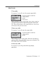
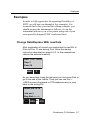
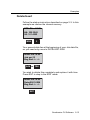
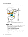
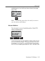
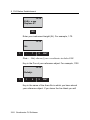
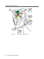
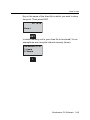
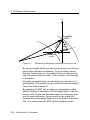
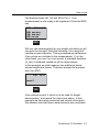
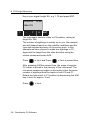
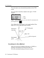
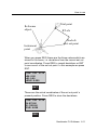
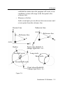
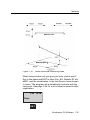
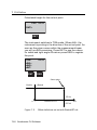
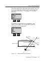
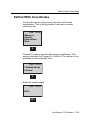
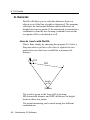
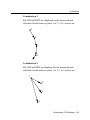
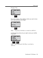
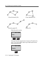
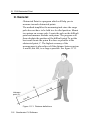
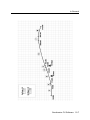
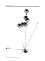
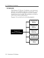
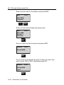
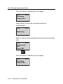
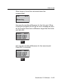
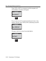
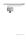
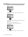
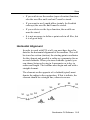
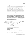
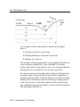
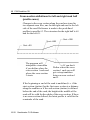
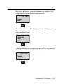
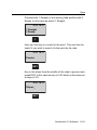
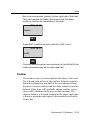
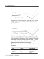
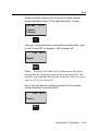
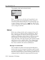
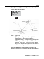
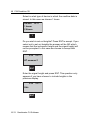
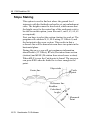
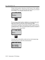
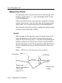
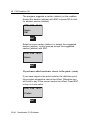
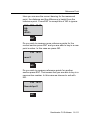
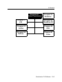
16 P39 RoadLine 3D
Reference Point
The program can be used to mark out the road design with
bonings (guide stakes), i.e. rods with height marks for the
road embankments.
This is practical in those cases you have to dig the cut slope
or place material to create the fill, when the bonings (guide
stakes) have to be located outside the road embankment.
The program can both be used for setting out and surveying
reference points along the roadline.
Setout
When setting out the operator enters the point code for the
road embankment or the section (station) and centre line
offset for the reference point, i.e. first the road embankment
and then a distance to where the reference point should be
located. See figure 16.16. The program uses the direction of
the line sloping from the previous break point in the cross
section.
Note – dELE runs with the slope of the roadway.
Centre line
Point 1
RefPoint
Distance
Point code=
Road embankment
Def. point
Figure 16.16
16-86 Geodimeter CU Software
Boning height*
* Guide stake
height
Reference Point
For highways the distance can have to be entered with a
negative sign for the road embankment closest the centre
line if this lies in the middle of the two road halves. This
reference point must be located a bit inside the roadway if
you wish to have a correct height, depending on that the
program otherwise will use the embankment slope.
Setting out two reference heights on the same rod.
The program also gives you the opportunity to setting out
two reference points on the same rod. Default is that
reference point 1 indicates one road embankment and that
reference point 2 indicates the other. See figure 16.17.
RefPoint 2
Centre line
RefPoint 1
Distance
Point code=
Point code=
Road embankment 2 Road embankment 1
Def. point
Def. point
dELE
Boning height*
*Guide stake
height
Figure 16.17
Measuring
When measuring the operator enters the section (station)
and centre line offset for the def. point. Then you measure a
optional number of reference points, see fig. below.
Geodimeter CU Software 16-87
16 P39 RoadLine 3D
Ref. point no.1
Ref. point no.2
P1
Ref. point no.3
Centre line
DHT=0
def.pnt.
Reference Point - Setout
Select program 39 and press ENT until this display
appears.
PRG
3
9
ENT
Select 6 Ref.Point and press ENT.
Roadl. 3D 10:17
4 Measure
5 Slope stake
6 Ref. Point
6
ENT
16-88 Geodimeter CU Software
Reference Point
Key in the job file in which you wish to store data for the
reference points and press ENT.
P39 10:17
Job no=_
ENT
Note – Displayed if Job/Mem is switched on (MNU61)
Select in which memory unit you wish to store data for the
reference points and press ENT. In this case we select 1
Imem.
P39 10:17
1 Imem OFF
2 Xmem OFF
3 Serial OFF
1
ENT
Note – Only displayed if Job/Mem is switched on
(MNU61)
Is this the station you chose when you ran program 20,
prior to P39? If no station establishment has been made,
P39 will automatically start P20.
It is impossible to start with setting out before you have
established your instrument. In this example we accept the
station and press ENT.
Geodimeter CU Software 16-89
16 P39 RoadLine 3D
P39 10:17
Stn=_
ENT
Key in the name of the area file in which the roadline data is
stored and press ENT.
P39 10:17
Area=_
ENT
Select in what type of device the roadline data is stored. In
this case we choose 1 Imem.
Sel.dev.
10:17
1 Imem
2 Xmem
1
Enter the signal height and press ENT.
P39
10:17
SH=_
ENT
16-90 Geodimeter CU Software
Reference Point
Key in the point code for the definition point that has the
correct centre line offset and press ENT, or leave the line
blank to enter the centre line offset manually.
P39
10:17
Pcode=
ENT
The program checks your chosen roadline. Please wait.
P39
10:17
Roadline check
Please wait
Select which section interval you shall have in this roadline
and press ENT. If you chose this interval when you stored
the roadline, the program selects that value.
P39
10:17
SecInc=
ENT
Geodimeter CU Software 16-91
16 P39 RoadLine 3D
Select 1 to set out reference points, 2 to measure reference
points or 3 to end program. In this case we select 1 Setout.
P39 10:17
1 Setout
2 Measure
3 Exit
1
Key in a boning (guide stake) height if you wish to move up
the setout point on the rod and press ENT.
P39
10:17
HT.ofs=
ENT
Press ENT if you wish to set out two elevations on the same
rod. In this case we press NO to set out only one point.
P39
10:17
Dual elevations?
NO
Do you know which section (station) is closest to the point
you are about to set out you can key in this and press ENT.
Otherwise you leave the line blank and press ENT and let
the program calculate the closest section (station) to your
16-92 Geodimeter CU Software
Reference Point
position. See If you know which section is closest to the
point...(cont) page 16-94.
P39
10:17
Sect.=
ENT
Aim at the prism and press the A/M-key to start the
measurement.
STD P39 10:17
HA:
VA:
A/M
Press REG to store the measurement.
STD P39 10:17
HA:
VA:
SD:
REG
Geodimeter CU Software 16-93
16 P39 RoadLine 3D
The program suggests a section (station) on the roadline.
Accept this section (station) with ENT or press NO to look
for another section (station).
STD P39 10:17
Sect.=
Ok?
ENT
Select an even section (station) or accept the suggested
section (station). In this case we accept the suggested
section (station) with ENT.
STD P39 10:17
Sect.=
ENT
If you know which section is closest to the point...(cont)
If you have keyed in the point code for the definition point
the program suggests a centre line offset. Otherwise you
will have to key in the correct centre line offset. Press ENT
or key in a new value.
STD P39 10:17
Cl.ofs=
ENT
16-94 Geodimeter CU Software
Reference Point
Is the definition point data OK? If so, press ENT, otherwise
press NO. In this case we press ENT.
Ok? P39 10:17
Sect.=
Cl.ofs=
Pcode=
ENT
Key in a number for the reference point you are going to set
out.
P39 10:17
Pno=
ENT
Key in the distance that is valid between the definition point
and the point you are going to set out and press ENT.
P39 10:17
Dist.=
ENT
The program automatically adopts TRK-mode. Aim to the
prism to start the measurement.
TRK P39 10:17
HA:
dHA:
Geodimeter CU Software 16-95
16 P39 RoadLine 3D
As soon as the prism comes within the measurement beam
you will see dHD,i.e. how much you must change the
horizontal distance from the instrument.
+=increase
-=decrease
When you think that you are close enough to zero, press
REG to register the point or press ENT if you wish to set out
with the radial/right angle offset method.
TRK P39 10:17
dHA:
dHD:
dHT:
REG
Do you wish to set out more reference points for this
section press ENT and you are able to key in a new point
number and a new distance. In this case we press NO.
P39 10:17
more?
NO
Do you wish to set out new reference points for another
section press ENT. That means that you are able to key in a
16-96 Geodimeter CU Software
Reference Point
new section (station) number. In this case we choose to exit
with NO, in order to set out two reference points.
P39 10:17
New def.pnt?
NO
Select 1 to set out reference points, 2 to measure reference
points or 3 to end program. In this case we select 1 Setout.
P39 10:17
1 Setout
2 Measure
3 Exit
1
Key in a boning (guide stake) height if you wish to move up
the setout point on the rod and press ENT.
P39 10:17
Ht.ofs=
ENT
Geodimeter CU Software 16-97
16 P39 RoadLine 3D
Press ENT if you wish to set out two elevations on the same
rod. In this case we press ENT.
P39 10:17
Dual elevations?
ENT
Do you know which section (station) is closest to the point
you are about to set out you can key in this and press ENT.
Otherwise you leave the line blank and press ENT and let
the program calculate the closest section (station) to your
position. See If you know which section is closest to the
point...(cont) page 16-100.
P39 10:17
Sect.=
ENT
Aim at the prism and press the A/M-key to start the
measurement.
STD P39 10:17
HA:
VA:
ENT
16-98 Geodimeter CU Software
Reference Point
Press REG to store the measurement.
STD P39 10:17
HA:
VA:
SD:
ENT
The program suggests the section (station) that lies closest
to the measured point. Accept this section (station) with
ENT or press NO to key in a new section (station).
P39 10:17
Sect.=
Ok?
ENT
Select an even section (station) or accept the suggested
section (station). In this case we accept the suggested
section (station) with ENT.
P39 10:17
Sect.=
ENT
Geodimeter CU Software 16-99
16 P39 RoadLine 3D
If you know which section is closest to the point...(cont)
If you have keyed in the point code for the definition point
the program suggests a centre line offset. Otherwise you
will have to key in the correct centre line offset. Press ENT
or key in a new value.
P39 10:17
Cl.ofs=
ENT
Is the definition point data OK? If so, press ENT, otherwise
press NO. In this case we press ENT.
Ok? P39 10:17
Sect.=
Cl.ofs=
Pcode=
ENT
Key in a number for the reference point you are going to set
out.
P39 10:17
Pno=
ENT
16-100 Geodimeter CU Software
Reference Point
Key in the distance that is valid between the definition point
and the point you are going to set out and press ENT.
P39 10:17
Dist.=
ENT
The program automatically adopts TRK-mode. Aim to the
prism to start the measurement.
TRK P39 10:17
HA:
dHA:
As soon as the prism comes within the measurement beam
you will see dHD,i.e. how much you must change the
horizontal distance from the instrument.
+=increase
-=decrease
When you think that you are close enough to zero, press
REG to register the point or press ENT if you wish to set out
with the radial/right angle offset method.
TRK P39 10:17
dHA:
dHD:
dHT:
REG
Geodimeter CU Software 16-101
16 P39 RoadLine 3D
The program suggests the centre line offset for the other
road half which is valid for the second definition point. Press
ENT.
P39 10:17
Cl.ofs= -x.xx
ENT
Is the definition point data OK? If so, press ENT, otherwise
press NO. In this case we press ENT.
Ok? P39 10:17
Sect.=
Cl.ofs=
Pcode=
ENT
Here is the difference in height between the first and
second reference point. Press Ent.
P39 10:17
dELE=
ENT
16-102 Geodimeter CU Software
Reference Point
Do you wish to set out more reference points for another
section (station) press ENT and you are able to key in a
new section (station) number. In this case we press NO.
P39 10:17
New def.pnt?
NO
Select 1 to set out reference points, 2 to measure reference
points or 3 to end program. In this case we select 3 Exit.
P39 10:17
1 Setout
2 Measure
3 Exit
3
Geodimeter CU Software 16-103
16 P39 RoadLine 3D
Reference Point - Measure
Select program 39 and press ENT until this display appears.
PRG
3
9
ENT
Select 6 Ref.Point and press ENT.
Roadl. 3D 10:17
4 Measure
5 Slope stake
6 Ref. Point
6
ENT
Key in the job file in which you wish to store data for the
reference points and press ENT.
P39 10:17
Job no=_
ENT
Note – Displayed if Job/Mem is switched on (MNU61)
Select in which memory unit you wish to store data and
press ENT. In this case we select 1 Imem.
P39 10:17
1 Imem off
2 Xmem off
3 Serial off
1
ENT
16-104 Geodimeter CU Software
Reference Point
Note – Only displayed if Job/Mem is switched on
(MNU61)
Is this the station you chose when you ran program 20,
prior to P39? If no station establishment has been made,
P39 will automatically start P20.
It is impossible to start with setting out before you have
established your instrument. In this example we accept the
station and press ENT.
P39 10:17
Stn=1
ENT
Note – Only displayed if Stn is switched on (MNU61)
Key in the name of the area file in which the roadline data is
stored and press ENT.
P39 10:17
Area=_
ENT
Geodimeter CU Software 16-105
16 P39 RoadLine 3D
Select in what type of device the roadline data is stored. In
this case we choose 1 Imem.
Sel.dev.
10:17
1 Imem
2 Xmem
1
Enter the signal height and press ENT.
P39
10:17
SH=_
ENT
Key in the point code for the definition point that has the
correct centre line offset and press ENT, or leave the line
blank to enter the centre line offset manually.
P39
10:17
Pcode=
ENT
16-106 Geodimeter CU Software
Reference Point
The program checks your chosen roadline. Please wait.
P39
10:17
Roadline check
Please wait
ENT
Select which section interval you shall have in this roadline
and press ENT. If you chose this interval when you stored
the roadline, the program selects that value.
P39
10:17
Sec.Inc=
ENT
Select 1 to set out reference points, 2 to measure reference
points or 3 to end program. In this case we select 2
Measure.
P39 10:17
1 Setout
2 Measure
3 Exit
2
Do you know which section (station) is closest to the point
you are about to set out you can key in this and press ENT.
Otherwise you leave the line blank and press ENT and let
the program calculate the closest section (station) to your
Geodimeter CU Software 16-107
16 P39 RoadLine 3D
position. See If you know which section is closest to the
point...(cont) page 16-109.
P39
10:17
Sect.=
ENT
Aim to the prism and press A/M to start the measurement.
STD P39 10:17
HA:
VA:
A/M
When the distance has been measured, press REG to
check the point you stand at.
STD P39 10:17
HA:
VA:
SD:
REG
16-108 Geodimeter CU Software
Reference Point
The program suggests a section (station) on the roadline.
Accept this section (station) with ENT or press NO to look
for another section (station).
P39 10:17
Sect.=
Ok?
ENT
Select an even section (station) or accept the suggested
section (station). In this case we accept the suggested
section (station) with ENT.
P39 10:17
Sect.=
ENT
If you know which section is closest to the point...(cont)
If you have keyed in the point code for the definition point
the program suggests a centre line offset. Otherwise you
will have to key in the correct centre line offset. Press ENT
or key in a new value.
P39 10:17
Cl.ofs=
ENT
Geodimeter CU Software 16-109
16 P39 RoadLine 3D
Is the definition point data OK? If so, press ENT, otherwise
press NO. In this case we press ENT.
Ok? P39 10:17
Sect.=
Cl.ofs=
Pcode=
ENT
Key in a number for the reference point.
P39 10:17
Pno=
ENT
Aim at the prism and press A/M to start the measurement.
STD P39 10:17
HA:
VA:
A/M
When the prism has been found, press REG to register the
measurement.
STD P39 10:17
HA:
VA:
SD:
REG
16-110 Geodimeter CU Software
Reference Point
Here you can see the correct bearing for the measured
point, the distance and the difference in height from the
reference point. Press ENT to accept this or NO to ignore.
Ok? P39 10:17
HA:
HD:
dELE:
ENT
Do you wish to measure more reference points for the
current section press ENT and you are able to key in a new
point number. In this case we press NO.
P39 10:17
more?
NO
Do you wish to measure reference points for another
section press ENT. That means that you are able to key in a
new section number. In this case we choose to exit with
NO.
P39 10:17
New def.pnt?
NO
Geodimeter CU Software 16-111
16 P39 RoadLine 3D
Select 1 to set out reference points, 2 to measure reference
points or 3 to end program. In this case we select 3 Exit.
P39 10:17
1 Setout
2 Measure
3 Exit
3
16-112 Geodimeter CU Software
Registered Data
Registered Data
This list below shows which data will be stored after
registration. See the configuration part if you wish to store
other data.
Job file
Label
3 Setout
Job file
Label
5 Slopestake
Section
80
Section
80
Centre line offs.
83
Pcode
4
ELE
39
Ht.Ofs.
36
Layer
86
Radofs
72
Layer height
87
RT.ofs
73
Ht.Ofs.
36
dELE
42
dN
40
N
37
dE
41
E
38
dELE
42
ELE
39
4 Measure
Section
80
Centre line offs.
83
dELE
42
Pcode
4
Layer
86
Layer height
87
N
37
E
38
ELE
39
continue next page...
Geodimeter CU Software 16-113
16 P39 RoadLine 3D
Job file
Label
Job file
6 Reference pnt
1 Setout, two ref. points
1 Setout, one ref. point
Same data as for one ref. point
Label
+
Section
80
Centre line offs.
83
Centr line offs.
83
dELE
42
Pno
5
Ht.ofs.
36
2 Measure
Distance
89
Section
80
dN
40
Centr line offs.
83
dE
42
E
39
Pno
5
HA
7
16-114 Geodimeter CU Software
HD
11
dELE
42
CHAPTER
17
P40 U.D.S.
17
In General .......................................................................... 17-2
Program Generation ..................................................... 17-3
Creation of U.D.S´s....................................................... 17-3
Standard Labels ............................................................ 17-3
Label Types................................................................... 17-4
How to use ....................................................................... 17-10
U.D.S Examples.......................................................... 17-14
Choice of Storage Unit ................................................ 17-17
17 P40 U.D.S.
In General
U.D.S will allow the operator to create own User Defined
Sequences for the registration and display of measurement,
coding and administrative data. Creation of the sequences is
carried out directly from the keyboard of the instrument or
transferred from an external device via the serial port.
What advantage can be gained with U.D.S
• It is possible to create and store up to 20 U.D.S´s in the
instrument.
• The existence and use of a buffer memory in the
instrument allows data to be stacked, which leads to
simplified and accelerated data registration.
• It is possible to create and store up to 16 user defined
labels (No 84-99) in the instrument.
• Measurement status is always under complete operator
control with the help of the automatic display of
program prompts in the instrument.
• All labels and values can be duplicated, incremented or
decremented automatically. This means that the labels
can be registered in a Geodimeter Memory Device
(GMD) without even seeing them in the display and
without the need to press the ENT key for duplicating
and incrementing/decrementing.
17-2 Geodimeter CU Software
In General
Program Generation
Program 40 must be selected in order to create an U.D.S.
Once the sequence has been created it is not necessary to
run the program 40 in order to access the UDS. It is stored
in the memory of the instrument and can be directly
accessed by choosing the UDS program number. It will also
remain within the instrument until it is deleted or changed
by the operator. Program 0-19 are reserved for UDS´s. The
sequence is generated by specifying the program No, the
order of the desired labels=program prompts and label
types. Finally, the label No 79=End must be used to either
terminate, loop or link the U.D.S to another U.D.S.
Creation of U.D.S´s
On the next page is a list of Standard Labels. In addition,
user defined labels can be set with Program 41. The list and
table of label types is not sufficient to explain how and
when certain labels and label types are displayed in the
instrument during the creation of your U.D.S´s. You simply
key in the label´s corresponding number and type in the
desired order. In the event of making a mistake during the
creation of the U.D.S, the opportunity of correcting the
mistake is given by the program asking you to confirm the
choice of both label and label type. Your choice of labels
and label types is more easily understood when you start to
create your own U.D.S´s together with the help of the
following examples.
Standard Labels
The label list containing Label 0-83 possess certain
functions in Geodimeter CU operation. While creating
U.D.S´s, the operator can change the prompt text (P41) but
Geodimeter CU Software 17-3
17 P40 U.D.S.
the function of the label will remain the same. Labels 84-99
are reserved for arbitrary use by the user and can be defined
with the program 41, Set Label. Due to the flexibility of the
system, almost all label types can be used with all labels. In
P0 the only valid are 2, 6, 7, 8. Info 41 is shown if a wrong
label type is used.
Label Types
The label type determines the function of the label.
No
Label Type
Description
0
Registration
Collect values directly from the
instrument.
1
Prompting label
Enter data manually.
2
Set*
Set values directly in the instrument.
3
Duplicating
(auto. or man.)
Display both prompt and the last
registered value.
4
In/decrementing (auto.
or man.)
Automatic in/decrementing of the
previously stored value.
5
Loop/repeat END*
Return to the U.D.S to the first
program step.
6
Single Program END*
Return to the U.D.S to P0.
7
Link Program END*
Link the present U.D.S to another
U.D.S.
8
View label*
View a value.
9
Call U.D.S-program*
Start another
10
Logon*
Choose memory unit and Job file.
*Can not be stored
0-Registration
Registration of raw and/or calculated values from the
instrument. This type of label is chosen when measured and
17-4 Geodimeter CU Software
In General
calculated values can be collected directly from the
instrument, e.g. HA, VA, SD, N, E, ELE, HD, VD.
1-Prompting label
Enter data manually after the prompt. The default value of
the label will not be displayed.
Note – For label 21 the only label types that can be used
are 1&2
2-Set
These pre-set values e.g. Label 21=Hor.ref. angle can be set
directly in the instrument.
3-Duplicating (automatically or manually)
This label type is used for displaying both the prompt and
the last registered value (e.g. SH=0.75). This value can be
changed by overwriting or accepted by depressing ENT.
The first time you key in the label when you run the U.D.S
you are able to choose if the duplication should be
automatic or not. If so the next time you enter this program
step the label is automatically stored without being
displayed.
Note – If the same label and type exists in UDS that are
linked or called upon, the duplication, in/decremention
remains.
4-Incrementing/Decrementing (automatically or
manually)
The previously stored value belonging to the same label e.g.
Pno=3 is automatically incremented/decremented and can
be accepted and stored into instrument either manually or
automatically. Displayed values can be overwritten and/or
Geodimeter CU Software 17-5
17 P40 U.D.S.
accepted. The first time you key in the label when you run
the U.D.S you are able to choose if the
incrementation/decrementation should be automatic or not.
If so the next time you enter this program step the label is
automatically incremented/decremented and stored without
being displayed.
Note – When using Autodup or Autoincr(decr
Sometimes you are able to change the ”invisible” values
during a U.D.S sequence by using the function key and
enter a new value for the label, e.g. F6, ENT, SH=1.0, ENT.
5-Loop/repeat END
Choice of this label type will automatically return the
U.D.S to the first program step after registration of the last
data items in the measurement sequence.
6-Single Program END
Choice of this label type will return the U.D.S to program 0
after registration of the last data items in the measurement
sequence.
7-Link Program END
Choice of this label type will link the present U.D.S to
another U.D.S of the operators choice, allowing the field
operation to be registered as one complete sequence. Note
that in the linked U.D.S the logon procedure will not be run.
8-View Label
This label type is used when you wish to look at certain
values without changing them. Useful if you have Auto
dup./Auto inc. Note that the values will only show if you
17-6 Geodimeter CU Software
In General
have a measured distance. Change any value with the
function key.
9-Call U.D.S
If you choose this label type you are able to start another
U.D.S program as a subroutine. When the subprogram is
finished you return to the next step in the original U.D.S.
You can call upon U.D.S´s in max. 4 levels, otherwise you
will get Info 47.
Note – The labels that are unique in the subprogram will
not be reset when you restart the original U.D.S program.
10-Logon
Choose in which Job file you wish to store the data when
you make a registration. This label type can only be
accessed when starting the U.D.S from computer. In order
to register anything a logon step must be run through
otherwise Info 10 will appear when trying to register, link
or call.
Geodimeter CU Software 17-7
17 P40 U.D.S.
Is this how you would like to set up your own program?
Prog.
No
Prompts
used in
U.D.S
Label
No
Label
Type
1
Remarks
Program generation of general
project/Job data program
Logon
Operat
53
(10)
YES
3
Value seen, accept or key in new
Date
51
3
Value taken directly from instrument.
Time
52
3
-”-
Temp
56
1
Prompted for and keyed in
Press
74
1
-”-
End
79
6
Single program, return to P0
2
Program generation of inst.stn/Ref.Obj
data program
Logon
(10)
YES
Stn
2
1
Prompted for and keyed in
IH
3
1
-”-
RefObj
62
1
-”-
HA ref
21
1
-”-
End
79
7
Link this program to Prog. 3.
3
Program generation of survey point
data program
Pno
5
4
Incr/decr value seen, accept or key in
new.
Pcode
4
3
Duplicated value seen, accept or key in
new
SH
6
3
-”-
HA
7
0
Value taken directly from instrument
VA
8
0
-”-
SD
9
0
-”-
END
79
5
Prog. loops back to first step in this
sequence=Pno
17-8 Geodimeter CU Software
In General
The programs (sequences) on the previous page are only
examples of how you could design your field data recording
sequences. Normally the surveyor is aware of the different
types of projects in which he or she shall be involved and it
is therefore possible to design in advance those programs
which he or she may need and store them in instrument. In
the event of some unusual survey task turning up for which
time is no stored program, it is a case of just entering the
required sequence into instrument directly in the field.
Geodimeter CU Software 17-9
17 P40 U.D.S.
How to use
Select program 40 (U.D.S).
STD P0
10:16
HA=392.9095
VA=102.8955
PRG
0
4
ENT
You are now ready to begin with creation of the U.D.S´s 1, 2
and 3 on the previous page. First key in 1 and ENT.
P40 10:17
Prog.no=
ENT
1
Enter a name for the U.D.S –program. Press the ASCII-key
to enter an alphanumerical name (max 16 characters).
Press ENT when ready.
P40 10:17
P1
Name=_
ENT
Note – If the program already exists this question appears.
Press YES to view the program or NO and Yes to delete it.
17-10 Geodimeter CU Software
How to use
P40 10:17
Prog.no=1
View?
Press YES or ENT to put log on first in the program.
P40 10:16
Log on?
YES
Step 1 is Label No for operator. Key in 53 and ENT.
P40 10:17
P1 Step no 1
Label no=_
5
3
ENT
Label type=duplication type (3) as it is often same operator
who uses the instrument daily. Key in 3 and press ENT.
If you leave the line blank you will return to the previous
menu.
P40 10:17
P1 Step no 1
Label: Operat
Type=_
3
ENT
Geodimeter CU Software 17-11
17 P40 U.D.S.
Here you have a chance to change your mind e.g. if you
made a mistake with either label choice and/or label type.
In this example we press YES.
P40 10:16
P1 Step no 1
Dup: Operat
Ok?
YES
Label no for Date. Key in 51 and ENT.
P40 10:16
P1 Step no 2
Label no=_
5
1
This value will be taken directly from instrument as you
have chosen label type 0, you will not need to key in the
date. Key in 0 end ENT.
P40 10:17
P1 Step no 2
Label: Date
Type=_
0
ENT
Press YES to accept the label.
Carry on in this manner using the filled in example on
page 17-8. If you loose track as to where you are in your
17-12 Geodimeter CU Software
How to use
sequence you can easily see this by checking on the step
No.
P40 10:16
P1 Step no 2
Meas: Date
Ok?
YES
When you come to step No 6 which is the point at which
you wish to terminate the sequence, do as follows:
This is equivalent to choosing Label No 79=END. Press
only ENT.
P40 10:21
P1 Step no 6
Label no=_
Ok?
ENT
This is the label type for a single nonlinked sequence. Key
in 6 and ENT.
P40 10:21
P1 Step no 6
Label: Special
Type=
6
Geodimeter CU Software 17-13
17 P40 U.D.S.
Key in YES to accept the label.
P40 10:21
P1 Step no 6
Single
Ok?
YES
You are automatically returned to the program 0. In order to
be able to continue with sequence creation it is necessary
to choose Program 40 before starting with Program 2.
STD P0
10:21
HA:32.9960
VA:48.9088
U.D.S Examples
The design of U.D.S´s is of course dependent on how your
existing software accepts data recorded in CU. Formatting
possibilities must exist within the system so as to be able to
present the recorded and transferred data in a suitable lay
out. This may entail some small changes to existing data
transfer programs or even the necessity to create some new
ones.
17-14 Geodimeter CU Software
How to use
Recording of raw data
Prog 1 - General
Prog 2 - Stn Est
Label
Text
Type
Label
Text
Type
Logon
10
53
Operat
Logon
10
3
2
Stn
1
51
52
Date
3
3
IH
1
Time
3
62
RefObj
1
56
Temp
74
Press
1
21
HAref
1
1
79
END
7
79
END
6
Prog 3 - Survey with
heights
Prog 4 - Survey with no
heights
Label
Text
Type
Label
Text
Type
5
Pno
4
5
Pno
4
4
Pcode
3
4
Pcode
3
6
SH
3
7
HA
0
7
HA
0
8
VA
0
8
VA
0
9
SD
0
9
SD
0
79
END
5
79
END
5
Prog 5 - Survey
Prog 6 - Survey
Label
Text
Type
Label
Text
Type
5
Pno
4
7
HA
0
7
HA
0
8
VA
0
8
VA
0
9
SD
0
9
SD
0
79
END
5
79
END
5
Geodimeter CU Software 17-15
17 P40 U.D.S.
Recording of raw data and coordinates
Prog 8 - Survey with
heights
Prog 8 - Survey with no
heights
Label
Text
Type
Label
Text
Type
4
Pcode
3
4
Pcode
3
5
Pno
4
5
Pno
4
6
SH
3
7
HA
0
7
HA
0
8
VA
0
8
VA
0
9
SD
0
9
SD
0
37
N
0
37
N
0
38
E
0
38
E
0
79
END
5
39
ELE
0
79
END
5
Prog 10 - Survey without
heights and Pcode
Label
Text
Type
5
Pno
4
7
HA
0
8
VA
0
9
SD
0
37
N
0
38
E
0
79
END
5
17-16 Geodimeter CU Software
How to use
Choice of Storage Unit
If you press YES or ENT at the question ”Log on?” when
you create your U.D.S-program, you will be able to choose
in which memory unit and in what Job-file all data will be
stored when registering.
Note – If this logon routine is not included Info 10 is
shown and no registration can be done even if pressing the
REG-key.
Create a subroutine
Look at page 17-14. Program 1 is a general U.D.S-program
that are useful whenever you want to start a U.D.S
sequence. Instead of manually initiating this program you
can call upon this program from any of your other U.D.S
programs. Simply press ENT and choose type 9, Call
(Program 1), at the second step in your U.D.S-program.
This means that when you start your U.D.S program, e.g.
Program 2, the program automatically initiates program 1,
the general U.D.S-program. When the general program is
run through you are returned to the next step in program 2.
Enter program 40 and choose to create program 2. Answer
YES to logon. At step 1 press ENT.
P40 10:21
P2 Step no 1
Label no=_
ENT
Geodimeter CU Software 17-17
17 P40 U.D.S.
Choose label type 9, Call, and press ENT.
P40 10:21
P2 Step no 1
Label: Special
Type=_
9
ENT
Here you enter the program you want to call. In this
example we choose program 1 and press YES (ENT).
P40 10:21
P2 Step no 1
Label: Special
Call=_
1
YES
Accept the first program step with YES or ENT. Press NO to
re-enter. Continue with the following program steps.
P40 10:21
P2 Step no 2
Label no=_
Now lets start program 2 and see how it works.
Start program 2.
STD
P0 10:21
Program=_
2
ENT
17-18 Geodimeter CU Software
How to use
First the program runs through the logon procedure and
you choose in which Job file you wish to store the data.
UDS P2 10:21
Job no=_3
ENT
Choose in which memory unit you wish to store the data.
UDS P2 10:21
1: Xmem off
2: Imem off
3: Serial off
2
ENT
Now the program calls upon program 1.
Enter the general parameters…
UDS P1 10:21
Step: 2 Store
Date=2001.0211_
YES
Geodimeter CU Software 17-19
17 P40 U.D.S.
This is the last step in program 1.
When you press ENT you will return to step 2 in program 2.
UDS P1 10:21
Step: 5 Store
Instno=69000_
ENT
The program will continue step by step to the end of the
program.
UDS P2 10:21
Step: 2 Store
Stn=_
17-20 Geodimeter CU Software
CHAPTER
18
P41 Define Label
18
In General .......................................................................... 18-2
How to use ......................................................................... 18-3
18 P41 Define Label
In General
With program 41 you can define label no 84-99. Program
41 – Define Label is included in the following program:
Program 41
Define Label
Program 40
U.D.S
18-2 Geodimeter CU Software
How to use
How to use
Turn the instrument on and disengage the dual-axis
compensator with function 22.
Select program 41 (Define Label).
STD P0 10:21
HA:392.9095
VA:102.8955
PRG
4
1
ENT
Choose any label between 90-109. In this example we
choose 90 and press ENT.
P41 10:21
Label no=_
9
0
ENT
Here you can see any old definition that may exist. Press
the ASCII-key to adopt ASCII table and key in the
appropriate characters, e.g. 71 68 84 32 78 79 (colour) and
press ENT.
P41 10:21
Change to=F90
ENT
Geodimeter CU Software 18-3
18 P41 Define Label
When you are ready press only ENT instead of keying in a
label no. You will now return to program 0.
P41 10:21
Label no=_
18-4 Geodimeter CU Software
CHAPTER
19
P43 Enter Coordinates
19
In General .......................................................................... 19-2
How to use ......................................................................... 19-4
19 P43 Enter Coordinates
In General
With program 43 you can carry out storage of known
coordinates. These known values are stored in an Area file.
The data contained in these AREA files will take the format
Pno, Pcode, Northing, Easting and Elevation and must be
keyed in manually. Coordinates are entered with up to 7
positions and 4 decimals.
Transfer of point coordinates and elevation data banks
between computer and Geodimeter CU is carried out with
program 54, File transfer, or by sending serial commands.
See Geodimeter CU general for more information.
As the total number of Area files is unlimited (device
memory capacity is only limitation), the same point
numbers can be used as long as they are stored in different
Area files. Same point numbers can be stored in the same
Area file, however, it is always the point nearest the
beginning of the file which is recalled for use in Station
Establishment –P20 and SetOut – P23 calculations. If a
particular point has to be updated in an Area file, this can be
done with Edit, if the software is installed in your
instrument.
Program 43 – Enter coordinates is included in the following
programs:
19-2 Geodimeter CU Software
In General
Program 43
Enter Coordinates
Program
29
Program 41
RoadLine
Define
Label
Program
21
am 41
Z/IZ
Program
39
Program 41
RoadLine
3D
Define Label
Program
23
41
SetOut
Program
40
Program 41
UDS
Program
rogram 4124
RefLine
Program
61
Program 41
CoGo
Geodimeter CU Software 19-3
19 P43 Enter Coordinates
How to use
Switch on the instrument and go through the Start
procedure until the instrument is in theodolite mode.
Select program 43 (Enter Coordinates).
STD P0 10:16
HA:392.9095
VA:102.8955
PRG
4
3
ENT
In which device do you want to store the point coordinates.
In this example we choose 1 Imem.
Sel device 10:17
1: Imem
2: Xmem
1
Key in the name of the Area file in which you wish to store
the point coordinates and height values. In this example we
key in 25 and ENT.
P43
10:16
Area=_
2
5
ENT
19-4 Geodimeter CU Software
How to use
Do you want to store heights? In this example we choose to
do so. Press YES (ENT) to accept or NO to cancel.
10:16
HT measure?
YES
Key in the first point number you wish to store in the
Areafile. In this example we key in 1 and ENT.
P43
10:17
Pno=_
1
ENT
Here you have an opportunity to enter a Pcode for the
point. The program will propose the last Pcode entered.
Accept it, key in a new or leave it blank.
P43
10:16
Pno=1
Pcode=_
1
ENT
Geodimeter CU Software 19-5
19 P43 Enter Coordinates
Key in the Northing value of point number 1 and press ENT.
P43 10:16
Pno=1
Pcode=1
N=3456789.012
ENT
Key in the Easting value of point number 1 and press ENT.
P43 10:16
Pno=1
Pcode=1
E=1234567.789
ENT
Key in the height of point number 1 and press ENT.
P43 10:16
Pno=1
Pcode=1
HT=123.890
ENT
Press YES to store point number 1 or press NO to cancel.
In this example we press YES.
P43 10:16
Pno=1
Pcode=1
Store?
YES
19-6 Geodimeter CU Software
How to use
Key in the next point number or press only ENT when you
are finished. In this example we press ENT.
P43
10:16
Pno=_
ENT
You are now returned to program 0.
P0
10:16
Temp=20.0_
Geodimeter CU Software 19-7
19 P43 Enter Coordinates
19-8 Geodimeter CU Software
CHAPTER
20
P45 Pcode
20
In General .......................................................................... 20-2
How to use ......................................................................... 20-5
20 P45 Pcode
In General
Pcode provides the operator with the opportunity of calling
upon a point code library which can be directly created
from the instrument keyboard. After Pcode library creation
and keying in of the Pcode number, the appertaining Pcode
name will be displayed either for acceptance or rejection
and thereafter recording.
How do I create my very own point code library
This is done simply by choosing the program No 45=Pcode.
It then simply becomes a task of keying in the numerical
value of the point code followed by its equivalent alpha or
alphanumerical title. The instrument automatically adopts
the ASCII mode for this purpose and you consult the ASCII
table in your instrument user manual for the keying in of the
alpha/alphanumerical codes.
Pcode numbers range from 1-254; if Nos above this range
are chosen INFO 31 is displayed. The equivalent alpha
point code can contain up to 16 characters; in cases where
16 characters are required, the prompt ”Text=” will
disappear from the display during the creation of the point
code.
Maximum of stored points
The maximum number of characters which can be stored in
the point code library is limited to 800. In other words if all
the point codes stored in the library have a maximum
number of characters of 16, there would be enough room
for 50 point codes. However, as most point codes are
abbreviated, the storage room of 800 characters should
provide the operator with enough storage place for all point
20-2 Geodimeter CU Software
In General
codes her or she will require for storage of detail point code
numbers during e.g. a tacheometric exercise.
Note – The numeric value of the point code is stored, not
the title.
Activation/deactivation of Pcode
After the installation of Pcode in the instrument, it can be
activated or deactivated with the help of
menu 6.1-Switches.
MNU
6
1
Set
10:16
Targ.test
on?
AIM/REG
off?
Pcode
on?
This means that if Pcode is set to ON the keying in of a
numerical point code in e.g. an U.D.S, will automatically
result in the equivalent alpha/alphanumerical point code
being displayed in the instrument; its correctness is
confirmed by pressing ENT. If wrongly keyed in the point
code can be overwritten without having to clear the
wrongly chosen one with the CL-key.
There are however some occasions where operators are
very experienced and have been working with only numeric
Pcodes on field cards for years. On this occasion the Pcode
switch can be switched off. The instrument will always
adopt the last chosen ON/OFF mode at switch on. The
status of the switch can also be seen when keying in one´s
first point code number in a U.D.S, i.e. if the point code´s
equivalent alpha title is seen in the display after keying in
Geodimeter CU Software 20-3
20 P45 Pcode
the numeric code and pressing ENT, then the switch is set
to ON.
Note – In order to correct any wrongly keyed in point code
alpha title, so that it corresponds with its numerical point
code value, it is necessary to recreate it with the help of
Pcode.
The changing and deletion of wrongly keyed in data and the
insertion of a new can of course be carried out with EDIT, if
you have access to this software in the instrument.
Auto dup, auto incr/decr label types
When using the Auto dup/auto incr/decr feature with
Pcodes in U.D.S´s, wrongly keyed in values can be changed
without the prompt and its respective value being
duplicated in the recording device. This is done by using
the F4 function; this function must be used before pressing
the REG key. In cases where ordinary Dup and incr/decr
label types are used, use of F4 function will result in the
Prompt and its respective data being added to the already
in-buffer memory recorded data. In other words, the point
code data will be duplicated. This can be erased and
corrected with EDIT later, if you have access to that
particularly software. This applies to all data which has
been wrongly recorded while using the Auto dup, Incr/Decr
in the connected recording device. So even if you have
pressed the REG key, it is never too late to erase and/or
change and correct wrongly recorded point code data.
Correction of wrong and entry of new Pno and SH values
can be treated in the same manner.
20-4 Geodimeter CU Software
How to use
How to use
Switch on the instrument and go through the Start
procedure until the instrument is in theodolite mode.
The instrument´s station has been established. Select
program 45 (Pcode).
STD P0
10:16
HA=392.9095
VA=102.8955
PRG
4
5
ENT
Choose the numerical value of the pcode to which you wish
to give an alpha title. In this example we choose 1 and
press ENT:
P45
10:17
Pcode=_
1
The instrument adopts the ASCII mode, key in the complete
alpha title or abbreviated alpha title of the point code. In the
example we key in 87 65 76 76=WALL (see the ASCII
table).
P45
Pcode=
Text=
ASCII=
10:17
ENT
Geodimeter CU Software 20-5
20 P45 Pcode
Continue to create your Pcode library in this way until you
have stored all the alpha titles you need. When you are
finished, press ENT to return to P0.
P45
10:16
Pcode=2
Pcode in U.D.S and other programs
You have now stored, in the memory of the instrument, the
necessary alpha titles of most types of survey detail you
require to survey in during your tacheometric task. As soon
as you have established your instrument over the survey
station at which the survey measurements shall be carried
out you can take advantage of the alpha and alphanumerical
Pcodes stored in your Pcode library. When in the U.D.S, the
sequence prompts for the point code corresponding to the
type of survey detail which is to be measured and stored, all
you do is key in the relevant Pcode´s numerical value. After
its display, confirmation of its correctness is done by
pressing ENT on the instrument keyboard. Storage into
Geodat or any other external device is finalized by pressing
the REG key of the instrument after the point has been
measured.
Note – The numeric value of the point code is stored, not
the title.
Pcode can be entered directly in the following programs:
20-6 Geodimeter CU Software
How to use
U.D.S.
Program 22
Angle Meas
Program 45
Pcode
Program 23
SetOut
Program 24
RefLine
Program 29
RoadLine 2D
Program 39
RoadLine 3D
Geodimeter CU Software 20-7
20 P45 Pcode
20-8 Geodimeter CU Software
CHAPTER
21
P54 File Transfer
21
In General .......................................................................... 21-2
How to use ......................................................................... 21-3
21 P54 File Transfer
In General
Connect the two units with the appropriate cable and switch
them on. The instructions below describes how to transfer
files from the Control unit to the Station unit’s internal
memory:
21-2 Geodimeter CU Software
How to use
How to use
Operation at the source unit
Choose program 54
PRG
5
4
ENT
Choose from which device you want to transfer files. In this
example we choose 2 Imem.
From
1. Imem
2. Xmem
3. Serial
16:12
1
Here you can choose what type of file you want to transfer:
1. A jobfile 2. An areafile or 3 A U.D.S-file.
In this example we choose 1. A jobfile.
File
1. Job
2. Area
3. U.D.S.
16:12
1
Geodimeter CU Software 21-3
21 P54 File Transfer
Key in the name of the file. In this example we key in
Job=1.
16:12
From Imem
Job=
1
To which device are you going to send the chosen file/s
from the source unit. Here we choose 3. serial.
To
1. Imem
2. Xmem
3. Serial
16:12
3
Enter new serial parameters or accept the current. Here we
accept the current with enter.
P54
16:12
COM=1.8.0.9600
ENT
Note – Prepare the target unit before accepting the serial
parameters for a successful file transfer.
21-4 Geodimeter CU Software
How to use
The file/s are sent via the cable and the display shows.
“Wait” during the transfer and you will then exit program 54.
P54
16:54
Please Wait
Note – If info 19 appears during a file transfer that means
that the file transfer was not successful. In that case you
should run the file transfer again and look for where it fails,
that is when info 35 (Data error) will show. Then check
your file for any errors and if possible correct them with the
editor.
Operation at the target unit
Chose program 54
PRG
5
4
ENT
From which device are you going to send files to the target
unit. In this case it is 3. Serial.
From
1. Imem
2. Xmem
3. Serial
16:12
3
Geodimeter CU Software 21-5
21 P54 File Transfer
Enter the serial parameters which must be same as the
serial parameters at the source unit.
In this example we accept the current with ENT.
P54
16:12
COM=1.8.0.9600
ENT
What type of file should the transferred files be saved as:
1. Job, 2. Area or 3. U.D.S.
In this example we choose 1. Job since we are transferring
a Jobfile.
To
16:54
1. Job
2. Area
3. U.D.S
3
The unit is now ready to receive. Start the transfer from the
source unit.
To
16:54
Please Wait
3
21-6 Geodimeter CU Software
CHAPTER
22
P55 Job/Mem
22
In General .......................................................................... 22-2
How to use ......................................................................... 22-3
22 P55 Job/Mem
In General
Program 55 will enable the operator to change job name
and select memory device to store the job. When a program
is started the operator is prompted to key in the job name
and select memory if Job/Mem has been activated in MNU
6 1. If Job/Mem has been deactivated in MNU6 1 then
program 55 offers a fast way to change job name and/or
memory device
22-2 Geodimeter CU Software
How to use
How to use
Select program 55.
STD P0
16:12
HA: 22.9253
VA: 108.5321
PRG
5
5
ENT
The program will suggest the latest job name press ENT to
accept or key in a new name for the job file.
P55
16:12
Job=
ENT
Select in which memory you want to store the job file. Press
ENT to return to program 0.
P55
16:12
1: Imem on
2: Xmem off
3: Serial off
ENT
Geodimeter CU Software 22-3
22 P55 Job/Mem
22-4 Geodimeter CU Software
TRIM
3 mm BLEED
3 mm BLEED
TRIM
TRIM
3 mm BLEED
3 mm BLEED
TRIM
3 mm BLEED
TRIM
TRIM
3 mm BLEED
TRIM
TRIM
Trimble 5600 Series
Trimble Engineering and Construction Division
5475 Kellenburger Road
Dayton, Ohio 45424
U.S.A.
800-538-7800 (Toll Free in U.S.A.)
+1-937-233-8921 Phone
+1-937-233-9004 Fax
www.trimble.com
www.trimble.com
TRIM
3 mm BLEED
TRIM
TRIM
TRIM
3 mm BLEED
3 mm BLEED
TRIM
TRIM
3 mm BLEED
3 mm BLEED
TRIM
TRIM
3 mm BLEED