1
Geodimeter CU
®
User Guide Part 1
F
Version 03.00
Part Number 571 702 001
June 2005
Corporate Office
Trimble Navigation Limited
5475 Kellenburger Road
Dayton, Ohio 45424-1099
U.S.A.
800-538-7800 (Toll Free in U.S.A.)
+1-937-233-8921 Phone
+1-937-233-9441 Fax
www.trimble.com
Copyright and Trademarks
Copyright © 2001-2005, Trimble Navigation
Limited. All rights reserved.
Geodimeter, Terramodel, Tracklight and Trimble
are trademarks of Trimble Navigation Limited,
registered in the United States Patent and
Trademark Office.
The Globe & Triangle logo and Autolock are
trademarks of Trimble Navigation Limited.
All other trademarks are the property of their
respective owners.
Release Notice
This is the June 2005 release version 03.00 of the
Geodimeter CU User Guide part 1, part number
571702001. It applies to the Geodimeter CU
Control Unit
The following limited warranties give you
specific legal rights. You may have others, which
vary from state/jurisdiction to state/jurisdiction.
Hardware Limited Warranty
Trimble Navigation Limited warrants that this
hardware product (the “Product”) will perform
substantially in accordance with published
specifications and be substantially free of defects
in material and workmanship for a period of one
(1) year starting from the date of delivery. The
warranty set forth in this paragraph shall not
apply to software products.
Software License, Limited Warranty
This Trimble software product, whether provided
as a stand-alone computer software product, built
into hardware circuitry as firmware, embedded in
flash memory, or stored on magnetic or other
media, (the “Software”) is licensed and not sold,
and its use is governed by the terms of the
relevant End User License Agreement (“EULA”)
included with the Software. In the absence of a
separate EULA included with the Software
providing different limited warranty terms,
exclusions and limitations, the following terms
and conditions shall apply. Trimble warrants that
this Trimble Software product will substantially
conform to Trimble’s applicable published
specifications for the Software for a period of
ninety (90) days, starting from the date of
delivery.
Warranty Remedies
Trimble's sole liability and your exclusive
remedy under the warranties set forth above shall
be, at Trimble’s option, to repair or replace any
Product or Software that fails to conform to such
warranty ("Nonconforming Product") or refund
the purchase price paid by you for any such
Nonconforming Product, upon your return of any
Nonconforming Product to Trimble in
accordance with Trimble’s standard return
material authorization procedures.
Warranty Exclusions and Disclaimer
These warranties shall be applied only in the
event and to the extent that the Products and
Software are properly and correctly installed,
configured, interfaced, maintained, stored, and
operated in accordance with Trimble's relevant
operator's manual and specifications, and; (ii) the
Products and Software are not modified or
misused. The preceding warranties shall not
apply to, and Trimble shall not be responsible for
defects or performance problems resulting from
(i) the combination or utilization of the Product
or Software with hardware or software products,
information, data, systems, interfacing or devices
not made, supplied or specified by Trimble; (ii)
the operation of the Product or Software under
any specification other than, or in addition to,
Trimble's standard specifications for its products;
(iii) the unauthorized modification or use of the
Product or Software; (iv) damage caused by
accident, lightning or other electrical discharge,
fresh or salt water immersion or spray; or (v)
normal wear and tear on consumable parts (e.g.,
batteries). Trimble does not warrant or guarantee
the results obtained through the use of the
Product.
THE WARRANTIES ABOVE STATE TRIMBLE'S
ENTIRE LIABILITY, AND YOUR EXCLUSIVE
REMEDIES, RELATING TO PERFORMANCE OF
THE PRODUCTS AND SOFTWARE. EXCEPT AS
OTHERWISE EXPRESSLY PROVIDED HEREIN,
THE PRODUCTS, SOFTWARE, AND
ACCOMPANYING DOCUMENTATION AND
MATERIALS ARE PROVIDED “AS-IS” AND
WITHOUT EXPRESS OR IMPLIED WARRANTY
OF ANY KIND BY EITHER TRIMBLE
NAVIGATION LIMITED OR ANYONE WHO HAS
BEEN INVOLVED IN ITS CREATION,
PRODUCTION, INSTALLATION, OR
DISTRIBUTION INCLUDING, BUT NOT
LIMITED TO, THE IMPLIED WARRANTIES OF
MERCHANTABILITY AND FITNESS FOR A
PARTICULAR PURPOSE, TITLE, AND
NONINFRINGEMENT. THE STATED EXPRESS
WARRANTIES ARE IN LIEU OF ALL
OBLIGATIONS OR LIABILITIES ON THE
PART OF TRIMBLE ARISING OUT OF, OR
IN CONNECTION WITH, ANY PRODUCTS
OR SOFTWARE. SOME STATES AND
JURISDICTIONS DO NOT ALLOW
LIMITATIONS ON DURATION OR THE
EXCLUSION OF AN IMPLIED WARRANTY,
SO THE ABOVE LIMITATION MAY NOT
APPLY TO YOU.
TRIMBLE NAVIGATION LIMITED IS NOT
RESPONSIBLE FOR THE OPERATION OR
FAILURE OF OPERATION OF GPS
SATELLITES OR THE AVAILABILITY OF
GPS SATELLITE SIGNALS.
Limitation of Liability
TRIMBLE’S ENTIRE LIABILITY UNDER ANY
PROVISION HEREIN SHALL BE LIMITED TO
THE AMOUNT PAID BY YOU FOR THE
PRODUCT OR SOFTWARE LICENSE. TO THE
MAXIMUM EXTENT PERMITTED BY
APPLICABLE LAW, IN NO EVENT SHALL
TRIMBLE OR ITS SUPPLIERS BE LIABLE FOR
ANY INDIRECT, SPECIAL, INCIDENTAL OR
CONSEQUENTIAL DAMAGES WHATSOEVER
UNDER ANY CIRCUMSTANCE OR LEGAL
THEORY RELATING IN ANY WAY TO THE
PRODUCTS, SOFTWARE AND
ACCOMPANYING DOCUMENTATION AND
MATERIALS, (INCLUDING, WITHOUT
LIMITATION, DAMAGES FOR LOSS OF
BUSINESS PROFITS, BUSINESS
INTERRUPTION, LOSS OF BUSINESS
INFORMATION, OR ANY OTHER PECUNIARY
LOSS), REGARDLESS WHETHER TRIMBLE HAS
BEEN ADVISED OF THE POSSIBILITY OF ANY
SUCH LOSS AND REGARDLESS OF THE
COURSE OF DEALING WHICH DEVELOPS OR
HAS DEVELOPED BETWEEN YOU AND
TRIMBLE. BECAUSE SOME STATES AND
JURISDICTIONS DO NOT ALLOW THE
EXCLUSION OR LIMITATION OF LIABILITY
FOR CONSEQUENTIAL OR INCIDENTAL
DAMAGES, THE ABOVE LIMITATION MAY
NOT APPLY TO YOU.
NOT WITHSTANDING THE ABOVE, IF YOU
PURCHASED THIS PRODUCT OR
SOFTWARE IN THE EUROPEAN UNION,
THE ABOVE WARRANTY PROVISIONS
MAY NOT APPLY. PLEASE CONTACT YOUR
DEALER FOR APPLICABLE WARRANTY
INFORMATION.
Notices
Class B Statement – Notice to Users. This
equipment has been tested and found to comply
with the limits for a Class B digital device,
pursuant to Part 15 of the FCC rules. These
limits are designed to provide reasonable
protection against harmful interference in a
residential installation. This equipment
generates, uses, and can radiate radio frequency
energy and, if not installed and used in
accordance with the instructions, may cause
harmful interference to radio communication.
However, there is no guarantee that interference
will not occur in a particular installation. If this
equipment does cause harmful interference to
radio or television reception, which can be
determined by turning the equipment off and on,
the user is encouraged to try to correct the
interference by one or more of the following
measures:
– Reorient or relocate the receiving antenna.
– Increase the separation between the equipment
and the receiver.
– Connect the equipment into an outlet on a
circuit different from that to which the
receiver is connected.
– Consult the dealer or an experienced radio/TV
technician for help.
Changes and modifications not expressly
approved by the manufacturer or registrant of
this equipment can void your authority to operate
this equipment under Federal Communications
Commission rules.
Table of Contents
Welcome to Geodimeter CU
Control unit
Comments about this manual ..........................................B
Glossary of terms used with Geodimeter CU .................B
Environmental Information ............................................. E
1
Introduction
Unpacking & Inspection ................................................. 1-2
Inspection...................................................................... 1-2
The Control unit ............................................................. 1-2
Detachable Control Unit ............................................... 1-3
Assigned Control Units................................................. 1-4
Additional Control Units............................................... 1-4
The Display.................................................................... 1-6
Settings.......................................................................... 1-7
Key Functions .............................................................. 1-10
Alpha Character Keying in (Numeric CU) ................. 1-21
Alpha Character Keying in (Alphanumeric CU) ........ 1-22
Servo Control Keys (Num. and Alphanum. CU)........ 1-24
Continue Key .............................................................. 1-25
Temporary Horizontal Angle Key .............................. 1-25
2
Memory Units
Introduction .................................................................... 2-2
Unit Description ............................................................. 2-2
Unit Capacity ................................................................ 2-2
Program 54 – File Transfer ........................................... 2-3
Edit................................................................................ 2-3
Setting up Internal Memory as an Active Memory Device2-4
Info Messages ............................................................... 2-6
Data Communication .................................................... 2-6
Table of Contents
Setting up CU as an Active Memory Device.................. 2-7
3
Memory Structure
Introduction .................................................................... 3-2
Memory Structure .......................................................... 3-2
Job Files ........................................................................ 3-2
Area Files ...................................................................... 3-3
Edit File......................................................................... 3-4
File Transfer.................................................................. 3-5
4
Data Communication
Introduction .................................................................... 4-2
Data Transfer ................................................................. 4-2
Control Unit Personal Computer .................................. 4-2
Serial Communication.................................................... 4-4
Description of the Command Instructions .................... 4-4
Geodimeter Language (Geo/L) Syntax Structure ......... 4-6
Protocol ......................................................................... 4-8
Directory ..................................................................... 4-10
Kill .............................................................................. 4-11
Load ............................................................................ 4-12
Memory....................................................................... 4-13
Mode ........................................................................... 4-14
Output ......................................................................... 4-15
Position ....................................................................... 4-16
Read ............................................................................ 4-17
Trig.............................................................................. 4-20
Write ........................................................................... 4-21
Status Description ....................................................... 4-22
Table of Contents
5
Pre-Measurement
Office Setup ................................................................... 5-2
Connecting the External Battery to the Control Unit.... 5-2
Turn on Power............................................................... 5-2
Pre-Settings ................................................................... 5-5
Set Unit (e.g Metres, Feet, Grads, Degrees etc.)........... 5-6
Set Time & Date ........................................................... 5-8
Special Settings ........................................................... 5-13
Create & Select Display Tables .................................. 5-13
Create & Select a New Display .................................. 5-14
Number of Decimals ................................................... 5-18
Switches ...................................................................... 5-20
Standard Measure........................................................ 5-26
Select Type of Language ............................................ 5-27
Test Measurements ..................................................... 5-28
Measurement of Collimation & Tilt of Horizontal Axis. 529
Tracker Coll – Calibration of the Tracker (Only for Trimble
System 5600)..................................................... 5-35
Instrument Test............................................................ 5-37
6
Start Procedure
Start Procedure.............................................................. 6-2
Field Setup .................................................................... 6-2
Startup ........................................................................... 6-3
Calibration of Dual-Axis Compensator With Servo ..... 6-4
Calibration of Dual-Axis Compensator Without Servo 6-5
Pre-Setting of Temp., Press, Humidity, Offset & HAref6-7
Station Data (Instr. Height, Signal Height, Stn. Coord.)6-10
Coordinate System ...................................................... 6-15
Table of Contents
7
Carrying Out A Measurement
Distance & Angle Measurement .................................... 7-2
Standard Measurement (STD Mode) ............................ 7-2
Two-Face Standard Measurement (C1/C2) .................. 7-5
Fast Standard Mode ...................................................... 7-9
D-bar Measurement (D-bar Mode) ............................. 7-10
D-bar two-face Measurement (C1/C2) ....................... 7-13
Collecting Detail & Tacheometry (TRK-Mode)......... 7-18
Setting Out (TRK Mode) ............................................ 7-22
Setting Out Using Pre-calc. Bearing & Horizontal
Distances SHA &SHD ...................................... 7-23
Setting Out Using Coordinates ................................... 7-27
Measuring Differences Robotic Surveying (Servo).... 7-35
8
Direct Reflex (only DR Instruments)
In General ...................................................................... 8-2
Settings.......................................................................... 8-4
Standard Deviation........................................................ 8-4
Measuring method ........................................................ 8-5
Distance Interval ........................................................... 8-6
Pointer ........................................................................... 8-8
Measuring Object........................................................ 8-13
Distance C1/C2 ........................................................... 8-14
STD DR Measurement ................................................ 8-16
Problems to Reach the S_Dev..................................... 8-17
9
Surveying methods
In General (only servo) .................................................. 9-2
Conventional Surveying With Servo ............................ 9-2
Autolock (Only Servo).................................................. 9-3
Robotic Surveying (Only Servo) .................................. 9-3
Table of Contents
RMT Configuration......................................................... 9-4
Conventional Surveying With Autolock (Only Servo)..... 9-6
Important Information When Measuring With High
Accuracy (and Using the Instrument’s Tracker) . 9-6
How to Work With Autolock ........................................ 9-7
Aiming .......................................................................... 9-8
Robotic Surveying (Only Servo) .................................. 9-10
Important Information When Measuring With High
Accuracy (and Using the Instrument’s Tracker)9-10
Equipment ................................................................... 9-10
Radio Communication ................................................ 9-11
How to Work With Robotic Surveying ....................... 9-11
Search Window ........................................................... 9-13
Activation of the RPU................................................. 9-15
Aim & Measure........................................................... 9-17
Establishing Contact From a Detached Control Unit ... 9-19
Switch to Measurement Towards an Ordinary Prism... 9-20
Switch Back to Robotic Surveying ............................... 9-21
Search Functions in Robotic Surveying....................... 9-23
Automatic: on (in Autolock or Robotic Mode)........... 9-24
Adv.lock: on (Only in Robotic Mode) ........................ 9-24
RMT600TS: on (Only in Robotic Mode and With
RMT600TS) ...................................................... 9-25
Eccentric Point............................................................. 9-25
The RPU Menu ........................................................... 9-29
10
Important Pages
ASCII Table ................................................................. 10-2
General Measurement Hints........................................ 10-4
Backup of Memory ..................................................... 10-4
Reboot the Keyboard Unit .......................................... 10-4
Table of Contents
Collimation Errors ...................................................... 10-6
Tilt Axis ...................................................................... 10-6
How to Combine Labels 26, 27, 28 and 29................. 10-6
Fetch Station Data (MNU 33)..................................... 10-7
How to set out Using Autolock (Only Servo)............. 10-7
Measuring Towards Corners Using Autolock............. 10-8
How to Check What is Installed in Your Keyboard Unit...
10-8
Temporary Horizontal Angle in P0............................. 10-9
Description of Label 23 .............................................. 10-9
Info Codes ..................................................................10-11
11
Angle Measurement System
Overview...................................................................... 11-3
The Angle Measuring Technique ................................. 11-3
Dual Axis Compensator.............................................. 11-3
Correction for Collimation Errors............................... 11-4
Correction for Trunnion Axis Tilt............................... 11-4
Calculation of the Horizontal Angle ........................... 11-5
Calculation of the Vertical Angle................................ 11-5
Single-Face Angle Measurement ................................ 11-6
Two-Face Angle Measurement.................................... 11-6
12
Distance Measurement System
Overview...................................................................... 12-3
Distance Measurement................................................ 12-3
Standard Measurement (STD Mode) .......................... 12-4
Fast Standard Measurement (STD mode)................... 12-5
Switch Between Fast Standard and Standard Measurement
Mode ................................................................. 12-5
Precision Measurement (D-bar).................................. 12-5
Tracking Measurement (Setting Out) ......................... 12-6
Table of Contents
Measurement Towards Moving Targets...................... 12-7
Long Range Measurements......................................... 12-7
Target Data On/Off ..................................................... 12-8
Automatic Control of Signal Level............................. 12-9
Measurement Beam Width.......................................... 12-9
Measurement Range.................................................... 12-9
Accuracy ................................................................... 12-10
Important Information When Measuring With High
Accuracy ......................................................... 12-10
R.O.E (Remote Object Elevation)...............................12-10
Different Combinations of Instrument Height (IH) & Signal
Height (SH) ..................................................... 12-12
UTM Scale Factor Corrected Distances .....................12-14
UTM Example .......................................................... 12-15
13
Tracklight
Overview...................................................................... 13-3
How to Activate Tracklight......................................... 13-4
14
Servo
Servo Controls ............................................................. 14-2
Servo Control keys...................................................... 14-2
15
Tracker (only for servo instruments)
Overview...................................................................... 15-3
Tracker Operation ........................................................ 15-3
Search Criteria (OPTIONAL for Autolock) ............... 15-3
Lock on Target ............................................................ 15-4
Controlling the Tracker (OPTIONAL for Autolock) ....... 15-5
Window Control.......................................................... 15-5
Search Control ............................................................ 15-7
Table of Contents
Guidelines ................................................................... 15-9
Reference Control in Robotic Mode ......................... 15-10
16
Radio
Overview...................................................................... 16-2
Radio Controls ............................................................. 16-2
Select Radio Channel.................................................. 16-2
Station Address ........................................................... 16-2
Radio License.............................................................. 16-3
Radio Contact.............................................................. 16-3
Range .......................................................................... 16-4
Info Codes................................................................... 16-4
External Radio ............................................................. 16-5
17
Data Logging
Data Recording............................................................ 17-2
Control of Data Registration....................................... 17-3
Data Output ................................................................. 17-4
Standard Output .......................................................... 17-4
Tracking Mode (TRK) ................................................ 17-5
D-bar Mean Value Mode............................................. 17-5
User Defined Output ................................................... 17-7
How to Create an Output Table .................................. 17-7
Type of Memory Device ............................................. 17-9
1. Internal Memory ................................................... 17-10
2. Serial Output ......................................................... 17-11
Serial Commands ...................................................... 17-13
3 Xmem..................................................................... 17-17
Data Communication ..................................................17-19
CU PC ....................................................................... 17-19
Instrument With CU PC ............................................ 17-20
CU Instrument With CU ........................................... 17-20
Table of Contents
Instrument With CU Card Memory .......................... 17-21
Card Memory PC ...................................................... 17-22
18
Definitions & Formulas
Corrections for Refraction and Curvature .................... 18-2
Correction for Difference in Height .............................. 18-4
Correction of Horizontal Distance ................................ 18-5
Instrument Height ....................................................... 18-5
Signal Height .............................................................. 18-6
Atmospheric Correction ............................................... 18-6
19
Appendix A
Label List .................................................................... 19-1
20
Appendix B
Main Menu Configuration............................................. 20-1
Table of Contents
Welcome to Geodimeter CU
Control unit
Trimble® AB, has since the release of Geodimeter® System
400 presented a large number of inventions within the
surveying field; the tracklight®, the alpha-numeric
keyboard, servo, one-person total station etc.
In 1994 we introduced the first flexible total station,
Geodimeter System 600, which made it possible for the
user to physically tailor his or her total station to his/her
needs. In 1998 Geodimeter System 600 Pro was introduced
which included a number of technical improvements such
as a faster CPU and faster and smoother servo positioning.
The first introduction in 2000 was the Geodimeter 600
ATS. An instrument that can also be used for machine
control.
To improve productivity of the Geodimeter System 600
even further, a new Direct Reflex and servo driven model,
DR200+, was launched the same year.
The Trimble 5600 series was introduced in 2001 and in
2002 came the introduction of DR Standard and DR300+.
The system includes, of course, all the features that are
typical for Geodimeter, such as servo-assisted drive
(optional), numeric or alpha-numeric control units
(keyboards), tracklight, tracker (optional), radio side cover
(optional) and RS-232C communication.
-A-
Geodimeter CU General
Comments about this manual
If you or your colleagues have any comments on this
manual, we would be grateful to hear from you. Please
write to:
Trimble AB
Technical Information
Box 64
SE-182 11 DANDERYD
Sweden
Or send an e-mail to: [email protected]
Glossary of terms used with Geodimeter CU
Area File:
A file in a Geodimeter CU memory device
that holds known coordinates (Pno, N, E
etc.) or Roadline data.
A/M-key:
Aim/Measure button. Initiates a
measurement and controls search and
remote measurements.
D:
Accurate measurement with mean value
calc.
dH & dV:
These values represents the collimation
errors. When performing D-bar
measurements in two faces these errors are
blanked out and do not affect the accuracy
of the measurement (HA, VA). If the values
differs a lot from 0 it is recommended that
you perform a test measurement (MNU5),
see page 5-28.
Geodimeter CU General
-B-
Free Station: Also known as Resection. Location of the
total station by measuring distance and/or
angles to 2 or up to 8 points.
FSTD:
Fast Standard measurement, with A/M.
IH:
Instrument height over the point.
Job File:
A file in a Geodimeter CU memory device
that holds data collected in the field. This
file can consist of any data.
Log on:
Entering Job file and memory unit when
designing an U.D.S with program 40.
Offset:
Length offset to measured slope distance.
Prism const:
The prism’s length offset from the
0-constant.
Ref. Obj:
Reference Object, also back sight.
REG-key:
The register key. This stores data in the
data collector.
RMT:
Remote Measuring Target. The special
prism used when performing robotics
surveying (or remote surveying with auto
lock), i.e.carrying out one-person
measurements.
R.O.E:
Remote Object Elevation. See page 12-10.
RPU:
Remote Positioning Unit. The rod half of
the system when performing remote or
robotic surveying.
SH:
Signal height.
STD:
Standard measurement, with A/M.
-C-
Geodimeter CU General
TRK:
Tracking measurement, automatic and
continuous measurement.
U.D.S.:
User Defined Sequence. A program
designed by the user determining what is
collected, its order of collection and how it
is displayed on the screen.
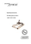
SH
dELE
IH
ELE
Geodimeter CU General
-D-
Point to set out
Environmental Information
NOTICE FOR TRIMBLE'S EUROPEAN UNION
CUSTOMERS
Trimble is pleased to announce a new
recycling program for our European
Union customers. At Trimble, we
recognize the importance of
minimizing the environmental impacts
of our products. We endeavor to meet
your needs, not only when you
purchase and use our products, but also
when you are ready to dispose of them.
That is why Trimble is actively
pursuing, and will continue to pursue,
the expanded use of environmentally
friendly materials in all its products, and why we have established
a convenient and environmentally friendly recycling program.
As Trimble makes additional recycling facilities available for
your use, we will post their locations and contact information to
our Recycling Instructions web page.
For product recycling instructions and more information, please
go to
www.trimble.com/environment/summary.html
Recycling in Europe:
To recycle Trimble WEEE,
Call +31 497 53 2430, and ask for the “WEEE Associate”
Or
Mail a request for recycling instructions to:
Trimble Europe BV
c/o Menlo Worldwide Logistics
Meerheide 45
5521 DZ Eersel, NL
-E-
Geodimeter CU General
Geodimeter CU General
-F-
CHAPTER
1
1
Introduction
Unpacking & Inspection ....................................................... 1-2
Inspection........................................................................ 1-2
The Control unit ................................................................... 1-2
Detachable Control Unit .................................................. 1-3
Assigned Control Units ................................................... 1-4
Additional Control Units .................................................. 1-4
The Display .......................................................................... 1-6
Settings ........................................................................... 1-7
Key Functions .................................................................... 1-10
Alpha Character Keying in (Numeric CU) ..................... 1-21
Alpha Character Keying in (Alphanumeric CU)............. 1-22
Servo Control Keys (Num. and Alphanum. CU)............ 1-24
Continue Key ................................................................ 1-25
Temporary Horizontal Angle Key .................................. 1-25
1 Introduction
Unpacking & Inspection
Before we begin to describe the operating procedure of
your Geodimeter Control Unit, it is first necessary to
acquaint yourself with the equipment & User manuals
received.
Inspection
Inspect the shipping container. If it is received in poor
condition, examine the equipment for visible damage. If
damage is found, immediately notify the carrier and the
Trimble sales representative. Keep the container and
packing material for the carrier’s inspection.
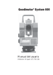
The Control unit
The CU is available in an alphanumeric version.The
alphanumeric control unit simplifies the entering of point
codes and basic editing by having all alpha characters on
separate keys. The alphanumeric control unit consists of 33
keys: the numerals 0-9, letters A-Z, and control keys. The
control keys comprise the choice of functions 0-126, choice
of menu, choice of program and choice of measurement
mode, together with clear and enter functions etc.see
figure 1.1.The control unit is more than just a keyboard, it
also contains the internal memory as well as any of the
softwares that are available.
1-2 Geodimeter CU General
The Control unit
Figure 1.1
Geodimeter CU alphanumeric control unit.
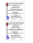
Figure 1.2
Geodimeter 600 CU alphanumeric control unit.
Detachable Control Unit
The control unit is detachable and this makes it very easy
for the user to transfer data. Simply detach the control unit
after a survey and bring it to the office (it’s very handy and
fits in a normal size pocket). Attach the control unit to a
computer using the multi functional cable. Run Program 54
or Terramodel® Field Data Module to transfer data between
the units.
Note – The control unit should not be attached/detached
when the instruments is switched on.
Geodimeter CU General 1-3
1 Introduction
Figure 1.3
How to attach/detach the control unit.
Assigned Control Units
In a surveying team each member can have his/her own
control unit with his/her own setups, software and internal
memory. This means that any operator can attach his/her
assigned control unit to any Trimble System 5600 and get it
to work with His/her specific U.D.S’s and setups.
Additional Control Units
With System 5600 you can work with two control units
attached at the same time: one at the back of the instrument
that serves as a master control unit and one at the front that
serves as a slave unit.
Having two control units attached at the same time can be
useful having in mind that they also contain internal
memories.
1-4 Geodimeter CU General
The Control unit
The control unit at the front can also be very useful when
measuring in two faces when you want to keep control of
the point to measure in face 2.
Geodimeter CU General 1-5
1 Introduction
The Display
The Geodimeter CU has a four-row Liquid Crystal Display
(LCD) where each row contains 20 characters. Both alpha
and numerical characters can be displayed. Black images
on a bright background make the display easy to read. The
display has illumination and adjustable viewing angle for
good readability under all conditions. The first row displays
the measurement mode, program choice, clock, indication
of returned signal (*) and battery condition ( ).
Figure 1.4
Geodimeter CU display
If an offset or a prism offset has been set this will be
indicated by (!) between the hour and the minute in the
clock. Alpha-numeric keyboard also display if alpha mode
α, shift (^) or lower case (1) is activated. The second to
fourth rows display the respective labels and values of
measurement. Each display table consist of a series of
“pages” which can be “turned” with the ENT-key.
1-6 Geodimeter CU General
The Display
Settings
MNU
1
3
By pressing MNU, 1, 3 you can set the following:
•
•
•
•
Display illumination
Reticle illumination
Contrast and viewing angle
Reflected Signal volume
Press the corresponding key below “Sel” to select what to
set. Use the corresponding key right below “Exit” to return
to the main menu.
Display illumination
Press the corresponding key below “OFF” to turn the
illumination ON/OFF. Press the corresponding key below
“<-” to decrease the illumination. When you have reached
the maximum resp. minimum illumination one of the
arrows is blanked out. The arrows will not be shown if the
option is turned off. A long press on the
key will turn
the display illumination on/off.
GUI 15:54
Illum Contrast
Reticle Vol
Sel <- -> Off Exit
Note – OFF indicates that the corresponding key below
will turn the option off.
Geodimeter CU General 1-7
1 Introduction
Contrast and viewing angle
Press the corresponding key below “<-” to decrease the
contrast and press the corresponding key below “<-” to
increase the contrast. When you have reached the
maximum resp. minimum contrast one of the arrows are
blanked out. The arrows will not be shown if the option is
turned off.
GUI 15:54
Illum Contrast
Reticle Vol
Sel <- -> Exit
Note – You will find that the contrast setting is most
effective under cold temperature conditions.
Reticle illumination
Press the corresponding key below “Off” to turn the
illumination ON/OFF. Press the corresponding key below
“<-” to decrease the illumination and press the
corresponding key below “->”. When you have reached the
maximum resp. minimum illumination one of the arrows is
blanked out. The arrows will not be shown if the option is
turned off.
GUI 15:54
Illum Contrast
Reticle Vol
Sel <- -> Off Exit
Note – Off indicates that the corresponding key below will
turn the option off.
1-8 Geodimeter CU General
The Display
Reflected signal volume
Press the corresponding key below “<-” to decrease the
volume level and press the corresponding key below “->” to
increase the volume level. When you have reached the
maximum resp. minimum level one of the arrows is
blanked out. The arrows will not be shown if the option is
turned off.
Hint! Aim the instrument towards the prism so that you can
hear the current volume level. Only in prism mode if it is a
DR instrument.
GUI 15:54
Illum Contrast
Reticle Vol
Sel <- -> Exit
User-defined display tables
With the “Config Display” application it is possible to
define your own display table, if the existing table does not
fulfil your needs during the execution of a special survey
application.
For further information refer to page 1-7. All labels in the
System can be displayed.
Geodimeter CU General 1-9
1 Introduction
Key Functions
ON/OFF key
PWR
Turns power on when pressed once, turns power off when
pressed again. If no key is pressed within 5 minutes from
power on the instruments automatically turns off.
When the instrument is turned on again within 2 hours from
latest use you will get the question “Continue Yes/No?”.
Powered off by
operator
Continue Yes/No?
If you answer yes to this question the Instrument returns to
the mode that was current when the Instrument was turned
off.
All the instrument’s parameters and all functions, such as
instrument height, signal height, coordinates, bearing, dual
axis compensation, etc. are stored in the instrument for two
hours. If you answer “NO” the Instrument is reset and some
parameters are lost, e.g. IH, SH.
Batlow Total Station
If batlow occurs no measurements can be carried out. The
next time (within 2 hours) the instrument is turned on you
will be prompted “Powered off by battery low?”. Answer
yes to return to the mode that was current before battery
low. Note that no measurements can be carried out before
replacing the drained battery or connecting an external
battery to the instrument.
1-10 Geodimeter CU General
Key Functions
Battery condition
You can see the condition of the connected battery at the
end of the first row in the display. As the battery becomes
drained the battery symbol will change from full to empty.
Note that this function depends on the battery condition and
on the charging method and should only be regarded as a
coarse indication.
Function keys/labels
The data stored under labels can be viewed or altered by the
operator. In some cases the data also influence the system.
Changing the data in the time label will, for instance, set the
system real time clock. However, just calling up a label,
viewing the data and restoring without any editing will not
influence the system at all. Data stored under labels can be
retrieved by the F (Function) key or in the U.D.S (User
Defined Sequences) (additional software).
A complete list of functions and labels can be found in
Appendix A.
Example: How to store a point number (Pno).
Turn on the instrument, press the function key.
Key in function 5 for point number and press the ENT-key.
F
I
11:41
Function=5
ENT
Geodimeter CU General 1-11
1 Introduction
The display shows the current value for the point number.
Accept the value by pressing YES or ENT or key in a new
value.
I
11:41
Pno=_
ENT
You now return to the mode that was current before you
pressed the function key. The new point number is now
stored in the instrument.
Menu key
MNU
Despite sophisticated built-in technology, operation is very
simple, since everything is controlled from the keyboard
and the self-instructive display.
Many functions are controlled from the MNU-system that
is presented on the display. The menu makes it easy to
follow and alter, if required, measurement units, display
tables, coordinates, correction factors etc. The main menu
configuration can be seen in Appendix B.
1-12 Geodimeter CU General
Key Functions
Example:
How to store the factor for atmospheric correction (PPM).
Turn on the instrument, press the MNU key. Select SET by
pressing 1.
Menu
1 Set
2 Editor
3 Coord
16:06
1
Select PPM by pressing 1.
16:06
Menu
1 PPM
2 Preset
3 Instr Setting
1
Key in the present value for temperature e.g + 20C.
Press ENT.
16:06
Set
Temp = 20.0
ENT
Geodimeter CU General 1-13
1 Introduction
Key in the present value for air pressure e.g 760mm/Hg.
Press ENT.
16:06
Set
Press = 760.00
ENT
Key in Relative Humidity. Default is 60%. (If you have
chosen Wet Temperature from MNU6.5 this will be shown
instead).
16:06
Set
RelHum = 60.0
ENT
Note – This menu is shown only if the switch “PPM Adv.”
is enabled in MNU6.1
The correction factor is immediately calculated and shown
in the display.
16:06
Set
RelHum = 60.0
PPM = 0.6
Input at label 56 and 74, via Function key also alters PPM
value. The PPM value can also be set directly by enter at
label 30.
1-14 Geodimeter CU General
Key Functions
Fast step-through menu
When you have become well acquainted with the menu
structure it is very easy to step to a submenu with a
minimum of key strokes. To go to menu 1.4.1, Set time (see
Appendix B) simply press the MNU-key followed by 141.
Program key
PRG
Choice of program. With this key you select the different
programs installed in your Geodimeter CU. The programs
comprise a number of different options which are listed
below. The operating instructions for each program are
described in a separate manual called “Geodimeter CU
User Guide Software”.
Option
Programs Supplied
UDS
P1-19 - User Defined Sequences
P20 - Station Establishment incl.
3-dim. free station
P40 - Create UDS
P41 - Define Label
Set Out
P23 - Set Out
P20 - Station Establishment incl.
3-dim. free
P43 - Enter Coordinates
P30 - Measure Coordinates directly to
an Area file
Pcode
P45 - Define Pcode
Edit
P54 - File Transfer
View
-
Internal Memory
P54 - File Transfer
Geodimeter CU General 1-15
1 Introduction
Option
Programs Supplied
DistOb
P26 - Distance / Bearing. between
RoadLine2D
P29 - RoadLine2D
or
P39 - RoadLine3D
RoadLine3D
P20 - Station Establishment incl.
2 objects
3-dim. free station
P43 - Enter Coordinates
P30 - Enter Coordinates directly to an
Area file
Z/IZ
P21 - Ground/Inst. Elevation
P43 - Enter Coordinates
RefLine
P24 - Reference Line
P20 - Station Establishment incl.
3-dim. free station
P43 - Enter Coordinates
P30 - Enter Coordinates directly to an
Area file
Ang. Meas.
P22 - Angle Measurement (only for
Station Establishment
P20 - Station Establishment incl.
servo instruments)
3-dim. free station
Area Calc.
P25 - Area & Volume Calculation
MCF
P27 - Moving Coordinates Forward
Obstructed Point
P28 - Obstructed Point
Measure Coord.
P30 - Measure Coordinates directly to
an Area file.
Angle Meas.+
P32 - Angle Measurement +
Athletics
P60 - Athletics
CoGo
P61 - CoGo
Field Application
P65 - Field Application
Monitoring
P66 - Monitoring
1-16 Geodimeter CU General
Key Functions
Choose program
There are two ways to choose a program:
1. Short press
With a short press on the program key the operator will be
prompted to key in the desired program number. In this
example we key in 20, Station establishment, and press
enter.
STD
13:08
Program = 20
2. Long press
With a long press on the program key you step to the
program menu. Here you can display available programs
for Geodimeter CU. Any optional program that is not
installed in your instruments is surrounded by two
brackets, ( ).
UDS PO 13:08
640 632-05.00
Program 0
Dir <- -> Exit
<-Current library and program number
<-Instrument model and program ver.
<-Current program name.
<-Key functions.
Key functions:
Dir
Step between the UDS-, the PRG- and the
OPTIONS-library
<- ->
Step backwards/forwards in the chosen
library
Exit/MNU
Exit without starting any program
ENT
Start the chosen program
Geodimeter CU General 1-17
1 Introduction
Configuration menu
By choosing a program with a long press, you will also
have the chance to configure the chosen program in most
cases. See more about how to configure programs in the
“Geodimeter CU User Guide Software” manual.
Enter key
ENT
Activates keyboard operations and turns display table
pages, a switch of face or a compensator initiation.
Clear key
←
For correction of keyed in but not entered errors and to
break a search routine.
Standard mode key
STD or STD
1
Choice of Standard Mode. This key activates the Standard
Measuring Mode. The instrument automatically assumes
the STD mode after going through the Start-up Procedure.
Standard Mode is described in detail on page 7-2 and
page 12-4, see also Fast Standard mode on page 7-9 and
page 12-5.
1-18 Geodimeter CU General
Key Functions
Tracking mode key
TRK or TRK
2
Choice of Tracking Mode. This key activates the tracking
measurements (continuous measurements). Tracking Mode
is described in detail on page 7-18 and page 12-6.
D-bar mode key
D
or D
3
Choice of Automatic Arithmetical Mean value Mode. Dbar mode is described in detail on page 7-10 and page 12-5.
Tracklight key
Tracklight ON/OFF. See more about Tracklight on page 131. With a long key and one beep it turns on the display
illumination. With a long key an two beeps it resets the
Instruments Settings.
Electronic level key
Display of the horizontal electronics level. The electronic
level on Trimble instruments can be levelled without the
need to rotate the instrument through 90 degrees (100
grads). This is achieved by having two separate rows on the
display, each with its own separate cursor, to show the level
status of both axes of the instrument (see fig below). The
lower cursor indicates the levelling in the measuring
Geodimeter CU General 1-19
1 Introduction
direction and the upper cursor indicates the levelling
perpendicular to the measuring direction.
11:36
The accuracy of the electronic level, i.e. each individual left
or right movement of the cursor, represents 3c (300cc) =
approximately 1’ 40”. This level mode is termed the
“coarse level mode”. After calibration of the dual-axis
compensator, this level mode automatically changes to the
“fine level mode” which can be compared to the normal
accuracy of a 1-second theodolite. In this fine mode each
left or right single step movement of the cursor represents
20cc (approximately 7”). The fine level mode is designed
for use during traversing using force-centring.
Measurement keys
Start of measurements cycle (STD, FSTD, D-bar). Internal
storage of angle values in C2 and C1.
A/M
A/M-key at the front (on instruments with no front panel)
when measuring in two faces (C1 and C2).
1-20 Geodimeter CU General
Key Functions
Registration key
REG
For registration of measurement values. (In FSTD working
with UDS this key both measures and registrates with a
single press.
Alpha Character Keying in (Numeric CU)
α REG
It is also possible to enter alpha characters in the numeric
control unit. This is done by pressing the REG-key/ASCIIkey. If alpha characters are to be used in the middle of a
numeric point number or point code title, exit from and reentry into the alpha mode is achieved by pressing the
REG/ASCII key. Follow the example bellow.
The instrument also gives you the opportunity to select
special characters for different languages. This can be done
via Menu 6.6. A complete list of values for different
characters for different languages is shown on page 10-2.
Example: Alphanumeric input using the ASCII table
The point number to be keyed in is 12 MH 66 which is
the field notation for Point Number 12, which happens
to be a manhole with a 66 cm diameter cover.
Press F5 and ENT. PNO is seen on the display. Key in
12 Press the REG-key/Alpha-key- ASCII is seen on the
display. Key in 77 72 = MH. Press once again the
REG/Alpha key. Then key in 66. Finalize the keying in
by pressing the ENT key. This ASCII possibility can of
course be used with other functions – e.g. Operator,
Project, etc., etc. – in fact all functions except the labels
Geodimeter CU General 1-21
1 Introduction
which are directly connected with measured and
calculated survey values.
Alpha Character Keying in (Alphanumeric CU)
Alpha mode key (alphanumeric CU)
α
For activation / deactivation of the Alpha Mode. When the
Alpha mode is activated, it is indicated by an (a) symbol in
the right-hand corner of the display.
Note – It is also possible to enter alpha characters in
instruments with a numeric control unit, see page 1-21.
How to use the alphanumeric keys (alphanumeric
CU)
α
α
↑
↑
Lc
Lc
CON
CON
The numerical keys can be used both for ordinary numerals
and letters. To use the letters as indicated on each key, first
press key α the keyboard is now locked for letters, and this
is indicated by an (α) symbol in the upper right hand corner
of the display. To enter a particular numerical character in
combination with an alpha character, press the key ↑. A (^)
1-22 Geodimeter CU General
Key Functions
symbol in the upper right-hand corner of the display
window indicates that the shift key is activated. For small
letters, press Shift,↑ directly followed by “Lower
Case”, Lc.
The figure (1) in the upper right-hand corner of the display
window will appear immediately indicating lower case
mode. To return to numerical keys, press key α.
The instrument also gives you the opportunity to select
special characters (not shown on the keyboard). The special
characters differ between languages. Language is changed
via Menu 66. These special characters are displayed in the
bottom row in groups of five. To step between the different
characters press keys ↑ and CON.
The characters are entered by first pressing shift and then
the corresponding key below the character.
Lower case key (alphanumeric CU)
Lower case is used together with the Shift key, ↑ to be able
to use the alphanumeric keyboard with lower case letters.
This is indicated by the figure “1” in the right hand corner
of the display.
Lc
Lc
↑
Shift, ↑
Shift key (alphanumeric CU)
↑
Shift key. For entering a numeric value when the keyboard
is set in alpha mode, or vice versa and to answer NO to the
Geodimeter CU General 1-23
1 Introduction
questions shown in the display. When the shift key is
activated, this is indicated by a ^, sign in the right-hand
corner of the display.
Space bar key (alphanumeric CU)
SPC
0
Activated when selecting the alpha mode.
Servo Control Keys (Num. and Alphanum. CU)
When measuring in two faces, this key is used for switching
between C1 and C2.
or
7
Key for horizontal positioning.
A short press of this key results in a horizontal positioning
to the set HA Ref value. A long press of this key results in a
180 /200 grads horizontal rotation from the instrument’s
current direction.
or
8
Key for vertical positioning.
or
9
Note – when setting out:
– If you press this key without measured distance
ELE=the height at the theoretical set out point.
1-24 Geodimeter CU General
Key Functions
– If you press this key with measured distance
ELE=the height at the measured set out point.
– If you press this key longer than 1 sec. With
measured distance ELE=the height at the theoretical
set out point.
Key for both horizontal and vertical positioning.
or
6
Continue Key
CON
Continue key. With a press on this key you can leave the
editor if you are working with an alphanumeric keyboard.
In some of the internal software, this key can be used to exit
the program. Together with the PWR-key, this key reboots
the keyboard unit, see page 10-4.
Temporary Horizontal Angle Key
5
or
5
The temporary horizontal angle feature in program 0 can be
useful if you want to turn the instrument without affecting
the original HA. This function is called HA_L, Horizontal
Angle from a Line, and results in an extra line in the display
showing HA_L=0.0000. You activate the HA_L function
by pressing key 5 in Program 0. Reset HA_L by pressing
key 5 again. Exit HA_L with a long press on key 5.
Note – this function only works in Program 0.
Geodimeter CU General 1-25
1 Introduction
1-26 Geodimeter CU General
CHAPTER
2
2
Memory Units
Introduction .......................................................................... 2-2
Unit Description.................................................................... 2-2
Unit Capacity................................................................... 2-2
Program 54 – File Transfer ............................................. 2-3
Edit.................................................................................. 2-3
Setting up Internal Memory as an Active Memory Device ... 2-4
Info Messages................................................................. 2-6
Data Communication ...................................................... 2-6
Setting up CU as an Active Memory Device ........................ 2-7
2 Memory Units
Introduction
Geodimeter CU includes an internal memory for data
storage. When there is a need of more memory capacity,
Trimble offers an external memory unit, card memory. This
unit can be connected to the instrument during the survey
work and/or when finished the measuring operations. This
part of the manual will describe the internal memory.
Note – As a safety measure always backup your memory to
protect yourself from memory loss. It is easily done with
Program 54 which enables you to transfer Job. and Areafiles between different units.
See, Geodimeter CU User Guide Software for more
information.
Unit Description
Geodimeter CU are equipped with an internal memory for
the storage of raw data, point information and calculated
coordinate data. The memory volume is completely self
supportive and can be used separately without the need of
having other external memory devices connected. The total
memory capacity can be enhanced by connecting a external
memory device, card memory.
Unit Capacity
The internal memory of Geodimeter CU has a capacity of
appr. up to 8.000 points if storing of only Pno, HA, VA and
SD. Data can be stored in an unlimited number of files. All
Field Data=survey point information plus angles, distances
and calculated coordinates, are stored in a Job File an all
Know Data=survey site control point and traverse point
2-2 Geodimeter CU General
Unit Description
coordinates and elevations are stored in an Area File as
described in Memory Structure.
Program 54 – File Transfer
Program 54 is included with Internal Memory. This
program is designed for transferring Job-, Area- and U.D.Sfiles between different units. Internal transfer is also
possible within each unit. See Geodimeter CU User Guide
Software for more information about program 54.
Edit
With the program Edit installed in the Geodimeter CU it is
possible to view and change data that been collected and
stored in the internal memory. Edit is described in
Geodimeter CU User Guide Software.
Geodimeter CU General 2-3
2 Memory Units
Setting up Internal Memory as an Active
Memory Device
When you are using most of the programs in your
Geodimeter CU you will be prompted to select an active
memory device in which you can register your
measurements. If you wish to setup the internal memory as
an active memory device outside any program the
following steps must be taken.
First step to the main menu by pressing the MNU key.
STD
P0 14:32
HA: 114.0480
VA: 105.2660
MNU
In order to choose 4 Data comm. Press 4
Menu
1. Set
2. Editor
3. Coord
14:32
4
Choose option 1 Select device.
Data com 14:32
1. Sel. device
2. Create table
3. Output format
1
2-4 Geodimeter CU General
Setting up Internal Memory as an Active Memory Device
Choose 1 Imem (Internal memory)
Menu
1. Imem
2. Serial
3. Xmem
14:33
1
Press YES to continue or No to interrupt.
Imem
14:33
Imem ON?
YES
Select output table number (0-5 depending on instrument)
and then press ENT.
Imem
14:33
Table no=
ENT
Control of the output can be done by pressing the REG key
of the instrument (REG key?) or continues (Slave?).
Choose REG by REG key? answering YES or press NO to
be able to choose Slave.
Imem
14:33
REG key?
Geodimeter CU General 2-5
2 Memory Units
Info Messages
No
Message
20
Illegal label number
21
Parity error
22
No or wrong device is connected
22.3 means Xmem error
23
Time out normally seen after attempt to transfer data from
device
26
Backup battery to old
30
Syntax error
32
Not found (Files, points and/or programs)
34
Wrong data-record separator
35
Data error (Label not containing any value or text, i.e 5=)
36
Memory device is full
37
Protocol error
39
Overrun error
45
Incompatible device (e.g. when trying P50)
50
System error - contact your nearest service shop!
Data Communication
Computer as controller
When using RS 232C, the command shall be sent as a
normal ASCII string ending with the ETX sequence. In this
case Protocol is always assumed to be 0.
Geo / L Syntax Construction
O = Output data from memory
L = Load data into memory
K = Erase memory
M = Available memory
2-6 Geodimeter CU General
Setting up CU as an Active Memory Device
File Types
M = Job file
I = Area file
D = Protocol
Commands
Output / Input / Kill + File Type = Job No / Area No
Examples
OM=1
Output of Job No 1 from Geodat to
computer
LI=2
Load data into Area 2 from computer to
Geodat
KM=SITE2
Erase Job No SITE2 from Job file
O*C
Output of all catalogues from Geodat to
computer
K*
Re initializes the Geodat after System error
(Error 50), erases all memory
For more information see Chapter 4.
Setting up CU as an Active Memory Device
When using most of the programs to your instrument you
will be prompted to choose in which memory device you
wish to registrate your measurements.
If you wish to setup the memory outside any program the
following steps must be taken.
Geodimeter CU General 2-7
2 Memory Units
Connect the Geodimeter CU to the instrument and place it
in the Theodolite Mode by going through the start
procedure, P0.
You begin with calling upon the main menu. Press MNU
STD P0 14:32
HA: 114.0480
VA: 105.2660
MNU
In order to choose 4 Data comm. Press 4.
Menu
1 Set
2 Editor
3 Coord
14:32
4
Choose option 1 Select device. Press 1.
Data com 14:32
1. Sel. device
2. Create table
3. Output format
1
2-8 Geodimeter CU General
Setting up CU as an Active Memory Device
Choose option 3 Xmem. Press 3. If you wish to record into
the Internal Memory of Geodimeter press 1. Imem.
Menu
1. Imem
2. Serial
3. Xmem
14:32
3
Press YES to select or NO to interrupt.
Xmem
14:32
Xmem on?
YES
Select output table number 0-5 (depending on instrument)
and then press ENT.
Xmem
14:32
Table no=
ENT
Control of the output can be done by pressing the REG key
of the instrument (REG key?) or continues (Slave?).
Geodimeter CU General 2-9
2 Memory Units
Choose REG by pressing YES or press NO to be able to
choose Slave.
Xmem
14:32
REG key?
2-10 Geodimeter CU General
CHAPTER
3
3
Memory Structure
Introduction .......................................................................... 3-2
Memory Structure................................................................. 3-2
Job Files.......................................................................... 3-2
Area Files........................................................................ 3-3
Edit File ........................................................................... 3-4
File Transfer .................................................................... 3-5
3 Memory Structure
Introduction
This part will describe how the memory is structured and
what happens when data is stored and collected from the
memory.
Memory Structure
The memory structure of all Geodimeter memory units
makes it is easy to check and identify the stored data after
registration.
The memory is divided in two separate files which are
called Job- and Area-file. Both these files are fully flexible
according to number and size. The only limit is the total
storing capacity available in the memory.
The memory can be used to store two types of data: survey
measurements (Job-files) and known coordinates (Areafiles). These Job- and Area-files consist of separate
expansive memories which means that they can be updated
individually at any time without affecting other Job- and
Area-files. The total number of files is limited only to the
total capacity of the memory. The more raw data stored in
Job-files, the less known coordinate and elevation data can
be stored in Area-files and vice versa.
Job Files
In order to permit later identification of Job files, they are
given a numeric, alpha or alphanumeric title by the user. All
survey data are stored in a Job file. Even field calculated
coordinate and elevation data are stored in these files.
When complete, these files can be transferred separately to
3-2 Geodimeter CU General
Memory Structure
a computer while the unfinished files can remain in
Geodimeter Internal Memory.
New Job file
F
5
0
When you run most of the field calculation programs in
Geodimeter CU the program asks you to name the Job file
in which you wish to store the measured data. Job no=0does
already exist. If you wish to create a new Job file outside
the field programs you enter label 50 (F50) and key in the
new Job number. As an alternative, Program 55 Job/Mem
Setup can also be used to create a new job file.
The next time you register a measurement the data will be
stored in this Job file.
.
STD P0
14:32
Job no=0_
Area Files
Known coordinates and elevations can be keyed in
manually (P43), or transferred from a computer.
Area-files, which are used during setting out survey, can be
accessed by giving the name/number of the file in which the
set out data is stored.By doing this, the search for the point
is limited to just that particular file. Several different
Areafiles can be prepared in advance of the survey job e.g.
surveyors often know that they will be working in more
than one single area during the course of a week. All known
Geodimeter CU General 3-3
3 Memory Structure
data for particular sites can therefore be stored in different
Area files. This is especially advantageous if several points
have the same numbers. Area no=0 does already exist.
Edit File
Any Area- or Job-file can be edited with the program Edit.
With this program you can view and change the contents of
the file after registration.
AREA No
2
3
JOB No
2
AB
8
Free memory space
This is how the memory is structured. The more data that is
stored in the Area file the more the Job file will be “pushed
down in the memory” and the more the free memory space
will decrease.
In the above example the three files 2, AB and 8 represent
different survey jobs.
It is possible to continue in an existing Job file. If you
return to the survey site to update the job 2 the new data
will be appended on the old file and the files AB and 8 will
be “pushed further down”.
3-4 Geodimeter CU General
Memory Structure
File Transfer
When you transfer a Job file or an Area file the files are not
erased from the device in which they were originally stored.
They are copies of the data files which are transferred to the
other device.
When using Program 54 (See Geodimeter CU User Guide
Software) it is sometimes faster to transfer a Job file than an
Area file. That is because when transferring an Area file all
data in the Job file of the target unit must be pushed down
first in order to create room for the new Area file.
New Area File
AREA No
AREA No
JOB No
JOB No
Free memory
space
Before
Free memory
space
After
The possibility also exists for deleting Job and Area files
from a computer or a total-station. This would be done e.g.
to create more room in the Geodimeter Memory Device,
see Data Communication, Chapter 4.
The operation should be carried out only after a successful
transfer to a computer or another device.
Geodimeter CU General 3-5
3 Memory Structure
3-6 Geodimeter CU General
CHAPTER
4
4
Data Communication
Introduction .......................................................................... 4-2
Data Transfer ....................................................................... 4-2
Control Unit Personal Computer ..................................... 4-2
Serial Communication .......................................................... 4-4
Description of the Command Instructions ....................... 4-4
Geodimeter Language (Geo/L) Syntax Structure............ 4-6
Protocol........................................................................... 4-8
Directory........................................................................ 4-10
Kill ................................................................................. 4-11
Load .............................................................................. 4-12
Memory ......................................................................... 4-13
Mode ............................................................................. 4-14
Output ........................................................................... 4-15
Position ......................................................................... 4-16
Read ............................................................................. 4-17
Trig ................................................................................ 4-20
Write.............................................................................. 4-21
Status Description ......................................................... 4-22
4 Data Communication
Introduction
Geodimeter CU can be connected to an instrument. There is
also possible to connect a computer to the CU directly. The
data can thereafter be edited or used e.g. in a CADprogram.
This part of the manual will describe how to connect the
control unit to a computer and how to transfer the data.
Data Transfer
Any Geodimeter CU can be connected to an external device
via a built in serial interface. This part of the manual will
describe how to transfer data from and to the Geodimeter
CU.
Control Unit
Personal Computer
Connect the Control unit to a computer and a power supply
and turn on both units. There are two ways to transfer data
between these units:
1. with Program 54
Enter program 54 at the control unit and choose (From
Imem, To serial) to transfer files from the control unit to the
computer or choose (From serial, To Imem) to transfer files
in the other direction. In the second case the transfer is
initiated by copying the file from the computer to the
communication port. See more about program 54 in
Geodimeter CU User Guide Software.
4-2 Geodimeter CU General
Data Transfer
2. with RS-232 commands
By sending the appropriate commands from the computer
you can transfer data between the control unit and
computer. Look at page 4-8 for more information about
serial communication.
Geodimeter CU General 4-3
4 Data Communication
Serial Communication
This part of the manual describes the communication
language that is used when the Geodimeter CU is
communicating with a personal computer.
Description of the Command Instructions
This part of the manual describes the syntax for
communication via the RS232 serial communication port in
Geodimeter CU.
Not all commands apply to all devices, information about
this is given in the command description. Some of the
commands are new and other have additions which will not
apply to older versions of the software in the devices.
Bold characters, 0, must be written as given.
Text within hooks, <...>, is to be replaced with
appropriate characters.
Items within square brackets, [...], is optional and
need not to be entered.
Text within brackets, (...), is an ASCII control
characters, e.g. (CR) is equal to ASCII 13 Carriage
Return). The hooks and the brackets shall not be written.
All commands must be ended with a carriage return, the
line feed is not necessary. Syntax for END of Command is:
(CR) [(LF)]. In the following text this End of Command
sequence is omitted. The instructions contains the
following information:
Purpose:
Description of what the command does.
Syntax:
<The syntax> {devices for which the
command is valid}
4-4 Geodimeter CU General
Serial Communication
Comments:
Description of arguments etc.
Return:
Description of what is returned from the
receiver of the command. <status> is equal
to the messages given in the info list. Status
is not always returned. However the
prompt <eot> is always returned.
Details:
Special information.
Examples:
Some typical examples.
Abbreviations
<lbl>
Label, the tag which identifies the data.
<dta>
Data, the data itself
<cmd>
One character command
<dev>
One character device, which can be a
directory in the memory or device.
<arg>
One or more arguments, all arguments are
one character long. If two arguments are
one character long. It two arguments are
given which are contrary to each other the
last one is taken.
<dir>
<dev>
<file>
Name of the file to be up- or down-loaded.
<etx>
End of text. Used to separate data posts
from each other. When transfer from Stn,
<etx>=(CRLF). When input to Stn,
<etx>=(CR) or (CRLF).
<eot>
End of transmission. Tells the receiver that
transfer is completed.
Geodimeter CU General 4-5
4 Data Communication
<status>
Message. Tells if an error condition occurs,
or gives the status of requested system
parameter.
,
Separates arguments from label.
=
Separate labels from data.
(CR)
Carriage return terminates the command.
(LF)
Line feed.
Devices
Stn
Station unit
CU
Control unit
Gdt
Geodat
Arguments
‘I’
The Area directory
‘M’
The Job directory
‘U’
The U.D.S program directory
‘*’
All directory (Geodat)
Geodimeter Language (Geo/L) Syntax Structure
The Geodimeter language is developed in order to create a
standard for communication between devices in
Geodimeter Systems. The basic Geodimeter data structure
is data tagged with a label.
<lbl>=<dta>
e.g. 7=254.3496 Horizontal angle 254.3496
4-6 Geodimeter CU General
Serial Communication
From this is the language developed by addition of
commands and arguments in order to be able to direct data
to and from a destination.
<cmd><dev><arg>...,<labl>=<dta>(CR)[(LF)]
e.g. WG, 67=24572.358 Setout coordinate North set to
24572.358
Command types
There are two types of commands, one that requests data
from the device, and on that sends data to set the device.
Common for both types is that <eot> always is sent when
the command is executed and the system is ready for a new
command.
Sender:
<complete command>(CR)
Receiver:
[<status><etx>]
<lbl>=<dta><etx>]…
<eot>
The status consists of 1 to 3 digits and is recognized in that
no equal sign (=) is found before <etx>. A request type
command always gives a response with status and/or data
posts. While a set type command only responses with status
when an error condition occurs. The meaning of the status
number is equal to the normal messages given in the info
list.
When file are transferred:
Sender:
<cmd><dir>=<file>(CR)[(LF)]
Sender or receiver:<lbl>=<dta><etx>
<lbl>=<dta><etx>
<eot>
Geodimeter CU General 4-7
4 Data Communication
Commands when starting up the communication
Break <alt><b>to start the Geodimeter
PV, 20
to start compenstor calibration
PV,21
to switch off the Geodimeter
Return signals from the Geodimeter
@
the compensator is displayed
!
Geodimeter awaits answer, Y(es) or N(o).
Protocol
Standard protocol for Station unit, Control unit and
Geodat
Station unit
From program 582-04
Control unit
From program 588-01
Geodat
From program 594-01
Set
Meaning
Baud rate
(F78):
9600
Parity
(F78):
0
None
Character length:
(F78):
8
8 bits
Stop bits
(F78):
1
1 bit
Time Out:
-
10 sec
Software flow
control:
-
Always on
(Geodat)
4-8 Geodimeter CU General
Serial Communication
Xon character:
-
DC1(17)
Xoff
-
DC2 (19)
62
>
End of
transmission
F(79):
Geodimeter CU General 4-9
4 Data Communication
Directory
Purpose:
List of file catalogue in memory.
Syntax:
O<dir>C {Stn, Gdt, CU}
Comments:
<dir>
Is the dir argument. ‘I’, ‘M’, ‘U’ and ‘*’ are
used. If <dir> is set to ‘*’ the file catalogue
for all directories is output.
Return:
<lbl>=<file><etx>
<lbl>=<dta><etx>
<eot>
or
<status><etx>
<eot>
Examples:
OMC
File catalogue of all Job files in the JOBdirectory.
O*C
File catalogue off all files in the memory.
4-10 Geodimeter CU General
Serial Communication
Kill
Purpose:
Delete files in memory.
Syntax:
K<dir>[=<file>}] {Stn, Gdt, CU}
Comments:
<dir>
Valid directories for all devices are M, I
and U. For Geodat is also D valid. If the file
is omitted all files in the directory will be
deleted. If the directory is given a wildcard
* the entire memory will be deleted.
<file>
The file entry is the name of the specific
file to be deleted.
Return:
<eot>
or
<status><etx>
<eot>
Examples:
K*
Delete entire memory.
KI
Delete all area files.
KM=LOT
Delete JOB named LOT.
Geodimeter CU General 4-11
4 Data Communication
Load
Purpose:
Load Memory. Data according to the
standard format can be loaded into the
memory device.
Syntax:
L<dir>=<file>
{Stn, Gtd, CU}
L<dir><prot>=<file>
{Stn, CU}
LD
{Gdt}
Comments:
<dir>
Is the dir argument. ‘I’, ‘M’, and ‘U’ are
used.
<file>
Is the name of the file (max 15 characters).
The file name is case sensitive.
<prot>
Is the protocol number.
Return:
<*>
When this is received transmission of data
can start.
or
<status><eot>
Details:
4-12 Geodimeter CU General
If an error occurs.
The transmission can start after the
command is sent and the prompt <*> is
send back from the device. The data shall
be in the Geodimeter standard format. The
transmission is ended by the EOT
character. The EOT is given in F79 for
Geodimeter and CU, and as protocol
parameter 16 in Geodat.
Serial Communication
Examples:
LI=LOT6
The area file LOT6 is created and can be
loaded when the prompt * is received from
the device.
LU=15
U.D.S program 15 will be loaded into
GDM or CU.
LD
Loads the protocol file into Geodat.
Memory
Purpose:
Check for free memory.
Syntax:
M[G]
{Stn, Gdt}
M[R]
{CU}
Return:
<number of bytes left><etx>
<eot>
or
<status><etx>
<eot>
Examples:
Command
Return
M
31654
MG
31654
Bytes left in memory
Geodimeter CU General 4-13
4 Data Communication
Mode
Purpose:
Change measuring mode.
Syntax:
PG,3=<arg>{Stn}
Comments:
<arg>
0 STD-mode
1 TRK-mode
2 D-bar mode
3 FSTD-mode
4 D-bar mode, high resolution
Return:
<eot>
or
<status><etx>
<eot>
Details:
The command will work whether the
instrument is locked on a target or not.
Examples:
PG,3=0
Change to STD-mode
PG,3=1
Change to TRK-mode
PG,3=2
Change to D-bar mode
PG,3=3
Change to FSTD-mode
PG,3=4
Change to D-bar mode, high resolution
4-14 Geodimeter CU General
Serial Communication
Output
Purpose:
Output from memory.
Syntax:
O<dir>=<file> {Stn, Gdt,CU}
O<dir><arg>
{Stn, Gdt, CU}
O<dir><prot>=<file>{Stn, CU}
OD
{Gdt}
Comments:
<dir>
Is the dir argument. ‘I’, ‘M’, and ‘U’ are
used.
<file>
Is the name of the file (max 15 characters).
The file name is case sensitive.
<prot>
Is the protocol number.
<arg>
Is the argument field. One argument can be
used, ‘C’. The ‘C’ argument will give an
output of the file catalogue.
Return:
<lbl>=<dta><etx>
<lbl>=<dta><etx>
<eot>
or
<status><etx>
<eot>
Geodimeter CU General 4-15
4 Data Communication
Examples:
OM=A45
Job file A45 is send out.
OU=3
U.D.S program no 3 is output.
Position
Purpose:
Position the Station unit with servo.
Syntax:
WS=<servo command>{Stn}
Comments:
<servo command>
The servo command is divided in the following parts:
<cmd><ang><tol> [<ang><tol>]
<cmd> P
Tells Geodimeter to perform a position
task, to given angles in horizontal and/or
vertical. The angles in horizontal and/or
vertical. The angles can be given either via
the instrument keyboard or by the serial
command. Write (WG). Enter the labels 26
and 27 with the correct values and then use
the WS command to perform the
positioning.
<ang> H
Horizontal positioning
V
Vertical positioning
<tol> nn
Positioning tolerance, given in cc (0-99).
Tolerance=0 means no tolerance given,
typical accuracy is 2cc if set to 0.
Return:
<eot>
or
<status><etx>
<eot>
4-16 Geodimeter CU General
Serial Communication
Examples:
WS=Pho5V10 Position horizontal with 5cc accuracy and
vertical with 10cc accuracy.
WS=PH01
Position horizontal with 1cc accuracy.
WS=PV15
Position vertical with 15cc accuracy.
Read
Purpose:
Read Station unit or Control unit. Read of
measured data or data in specific labels.
Syntax:
RG=[<arg>][,<lbl>] {Stn}
RR=[<arg>][,<lbl>] {CU}
Comments:
<arg>
[S] Standard output
N Name output
D Data output
V Numeric output item by item
T test if signal from target. 300 is returned
if NO signal. 301 is returned if signal.
<lbl>
If a label is given, the contents of that label
is returned. When omitted measured data is
returned.
Return:
<status><etx>
Standard output
<lbl>=<dta><etx>
e.t.c…
<eot>
or
Geodimeter CU General 4-17
4 Data Communication
<status><etx>
Name output
<lbl name>=<dta><etx>
e.t.c…
<eot>
or
<status><etx>
Data output
<dta><etx>
e.t.c…
<eot>
or
<status><etx>
Numeric output
<lbl><etx>
<dta><etx>
e.t.c…
<eot>
or
<status><etx>
<eot>
Message or
Meas signal test
or
<lbl><dta>
Specific label
<eot>
or
<lbl name><dta><etx>
Specific label with name
4-18 Geodimeter CU General
Serial Communication
<eot>
or
<dta><etx>Specific label only data
<eot>
or
<lbl><etx>Specific label numeric
<dta><etx>
Details:
When read of measure data, the output is
dependent on how the computer table in the
Geodimeter is set. See Geodimeter User
Manual for detailed information.
Examples
Command
RG
Return
Command
Return
0
RGN,5
Pno=104
RGN
0
7=10.2345
8=101.1005
RGD
9=145.324
HA=10.2345
0
VA=101.1005
10.2345
SD=145.324
101.1005
RGV
0
145.324
7
RGT
301
8
RG,5
5=104
9
10.2345
101.1005
145.324
Geodimeter CU General 4-19
4 Data Communication
Trig
Purpose:
Start of distance measurement in Station
unit.
Syntax:
TG[<arg>]{Stn}
Comments:
<arg>
Is the argument for short range ‘<’ or long
range ‘>’ measure. The ‘<’ is default and
need not to be entered.
Return:
<eot>
or
<status><etx>
<eot>
Examples:
TG or TG<
Start of short range measure.
TG>
Start of long range measure.
4-20 Geodimeter CU General
Serial Communication
Write
Purpose:
Write data into the Station unit or Control
unit. All labels that can be set by the
function key in the system can be written.
Syntax:
WG,<label>=<data>
{Stn}
WR,<label>=>data>
{CU}
Comments:
<label>
0-99
<data>
Maximum 9 digits for numeric type labels,
and maximum 16 characters for ASCII type
labels.
Return:
<eot>
or
<status><etx>
<eot>
Examples:
WG,5=10
Label 5 set to 10 in Station unit.
Geodimeter CU General 4-21
4 Data Communication
Status Description
Value
Description
0
Instrument operating correctly, all required data are
available.
3
The measured distance has already been recorded. A new
distance measurement is required.
4
Measurement is invalid and recording not possible
5
Recording is not possible with the selected mode setting of
the Geodimeter instrument.
10
No device connected
20
Label error. This label cannot be handled by the
instrument.
21
Parity error. this label cannot be handled by the instrument.
22
Bad or no connection, or wrong device connected.
23
Time Out
24
Illegal state to execute command. Occurs when trying to
communicate in C2-position.
30
Syntax error.
35
Data error.
4-22 Geodimeter CU General
CHAPTER
5
5
Pre-Measurement
Office Setup ......................................................................... 5-2
Connecting the External Battery to the Control Unit ....... 5-2
Turn on Power................................................................. 5-2
Pre-Settings ......................................................................... 5-5
Set Unit (e.g Metres, Feet, Grads, Degrees etc.) ........... 5-6
Set Time & Date.............................................................. 5-8
Special Settings ................................................................. 5-13
Create & Select Display Tables..................................... 5-13
Create & Select a New Display..................................... 5-14
Number of Decimals ..................................................... 5-18
Switches........................................................................ 5-20
Standard Measure......................................................... 5-26
Select Type of Language .............................................. 5-27
Test Measurements............................................................ 5-28
Measurement of Collimation & Tilt of Horizontal Axis ... 5-29
Tracker Coll – Calibration of the Tracker (Only for Trimble
System 5600)................................................................ 5-35
Instrument Test ............................................................. 5-37
5 Pre-Measurement
Office Setup
This chapter is to familiarize you with your Geodimeter CU
before you enter the field. We will not follow all steps in the
normal field procedure.
Connecting the External Battery to the Control Unit
When using the control unit detached from the instrument,
e.g. when performing remote surveying or robotic
surveying (se chapter.) or when connecting it to a computer
it is necessary to connect the control unit to an external
battery. Connect the external battery and the control unit
with the standard battery cable.
Turn on Power
To turn the instrument on, press the On/Off key. A built in
test sequence displays the following display tables.
PWR On/Off
A built in test sequence displays Geodimeter CU and type
number followed by…
Geodimeter CU
Connecting GDM
…display of the electronic level which indicates the level
status of both axes of the instrument. As no measurements
are to be made we will disconnect the dual axis
compensator by setting function 22 to 0. Select function 22.
5-2 Geodimeter CU General
Office Setup
I
11:41
.....
.....
.....
.....
F
2
2
ENT
Select 0 to disconnect the dual axis compensator and press
ENT.
11:41
Comp = 0
0
ENT
As no measurements are to be made, press only ENT.
PO 18:20
Temp = 20
ENT
As no measurements are to be made, press only ENT.
PO 18:20
Press = 760.0
ENT
Geodimeter CU General 5-3
5 Pre-Measurement
As no measurements are to be made, press only ENT.
PO 18:20
RelHum = 60.0
ENT
Note – This menu is shown only if “PPM Adv.” is
activated in MNU6.1
As no measurements are to be made, press only ENT.
PO 18:20
Offset = 0.000
ENT
As no measurements are to be made, press only ENT.
PO 18:20
HA: 192.8225
HAref =
ENT
5-4 Geodimeter CU General
Pre-Settings
Here you come automatically to the Standard Measurement
mode. As no measurements are going to be made at the
moment, we will continue with the Pre-Setting routine.
STD PO 18:20
HA: 192.8230
VA: 91.7880
Pre-Settings
In this exercise you will need to access Appendix B at time
to time to look at the main menu configuration. The subject
Settings can be divided into three different categories:
• Measurement settings of PPM, Offset, Haref and Station
data. These settings will be dealt with in the section
“Start Procedure” on page 6-2.
• Special measurement settings – these range from the
setting of decimal place and defining display tables to
setting different switches. These settings will be dealt
with on page 5-13“Special Settings”.
• Pre-Setting – settings which can be decided and
executed in advance are the following: MNU 65 = Unit
(i.e.metres, feet, grads, degrees, etc) and MNU 14 =
Time & Date.
Note – Coordinate System
Start with checking your coordinate system setting with
menu 67, see page 6-15.
Geodimeter CU General 5-5
5 Pre-Measurement
Set Unit (e.g Metres, Feet, Grads, Degrees etc.)
MNU
6
5
Now it is time to make use of the menu function. Press the
MNU key.
STD PO 18:20
HA: 192.8230
VA: 91.7880
MNU
You are going to begin the CONFIG routine. Press 6.
Menu 18:20
1 Set
2 Editor
3 Coord
6
Step by pressing ENT.
Config. 18:21
1 Switches
2 Standard Meas
3 Decimals
ENT
Note – This is not needed. If you know the “code” for
desired function just key in the entire code, in this case 65
in order to save key-strokes.
5-6 Geodimeter CU General
Pre-Settings
You are going to set the unit parameters – i.e., metres, feet,
grads, degrees, etc.
Press 5.
Config. 18:21
4 Display
5 Unit
6 Language
5
Answer YES or ENT to accept the displayed unit or NO if
you want to change to feet.
Here press ENT.
Config. 18:21
Metre?
ENT
Answer YES or ENT to accept, or NO if you want to change
to degrees, decimal degrees or Mills.
Here press ENT.
Config. 18:21
Metre
Grads?
ENT
Geodimeter CU General 5-7
5 Pre-Measurement
After you have answered YES or NO to the choice of
temperature unit, the air pressure unit and Wet
Temperature/Humidity, the program returns to Program 0.
Config. 18:21
Metre
Grads
Celsius?
Note – “Wet Temperature” must always be a lower figure
than “Temp” otherwise you`ll get an error message in the
display.
By pressing F23 you can see the units you have chosen
according to the following: xxx1=Grads (400), xxx2=
Degrees (360, min, sec), xxx3=Decimal Degrees (360),
xxx4=Mills (6400), xx1x=Meter, xx2x=Feet,
x1xx=Celsius, x2xx=Fahrenheit, 1xxx=mbar,
2xxx=mmHg, 3xxx= inchHg, 4xxx=hPa.
Example: F23 shows ´3121´ means that inchHg, Celsius,
Feet and grads have been choosen.
Set Time & Date
MNU
1
4
Now it is time to make use of the MNU function. Press MNU
key.
STD PO 18:24
HA: 192.8230
VA: 91.7880
MNU
5-8 Geodimeter CU General
Pre-Settings
You are going to begin the SET routine, Press 1.
Menu 18:24
1 Set
2 Editor
3 Coord
1
Step by pressing ENT or 4 directly.
Set 18:24
1 PPM
2 R.O.E
3 Instr Setting
ENT
You are going to set the clock, Press 4.
Set 18:24
4 Clock
4
You wish to calibrate the clock. Press 1.
Time 18:24
1 Set time
2 Time system
1
Geodimeter CU General 5-9
5 Pre-Measurement
Note – Time and date can also be set by using function 52
(F52) and function 51 (F51).
These values were in the instrument at the time it left the
factory. Key in today´s actual values and press ENT.
Time 18:25
Date = 2001.0201
ENT
Key in your time. Press ENT when the time is synchronized.
Time 18:25
Date = 2001.0201
Time = 18.2540
ENT
You are returned to prog. P0. If you are not used to the
order of year/month/day and would rather have the normal
European standard of day/month/year, press MNU.
STD PO 18:25
HA: 192.8230
VA: 91.7880
MNU
5-10 Geodimeter CU General
Pre-Settings
Choose Set by pressing 1.
Menu 18:26
1 Set
2 Editor
3 Coord
1
Press the ENT key or 4 direct to access the clock option.
Set 18:26
1 PPM
2 Decimals
3 Unit
ENT
Choose clock by pressing 4.
Set 18:26
4 Clock
4
Choose Time system by pressing 2.
Time 18:26
1 Set time
2 Time system
2
Geodimeter CU General 5-11
5 Pre-Measurement
Here you are able to select which type of date system you
want – e.g Numerical? 12h mm-dd-yyyy or 24h mm-dd-yyyy
and also if you want to change to dd-mm-yyyy. Let´s press
YES or ENT for Numerical.
Time 18:20
Numerical?
ENT
You are returned to the Standard mode program 0 (P0).
STD PO 18:20
HA: 192.8230
VA: 91.7880
You have now completed the pre-settings, which normally
don´t have to be changed.
Note – Check after service
If the instrument has been delivered for service you should
check time & date as these parameters might have been
changed.
5-12 Geodimeter CU General
Special Settings
Special Settings
The special measurement settings range from defining
display tables, setting decimal place and setting different
switches such as: Targ. Test, Pcode and Info ack.
Create & Select Display Tables
Various display combinations can be created by the
operator. However, we consider the following 3 tables as
standards and we have chosen them to be the default.
Table 0 (Standard)
STD PO 9:22
HA:
VA:
SD:
HA:Horizontal Angle
VA:Vertical Angle
SD:Slope Distance
ENT
STD PO 9:22
HA:
HD:
VD:
HA:Horizontal Angle
HD:Horizontal Distance
VD:Vertical Distance
ENT
STD PO 9:22
N:
E:
ELE:
N:Northing
E:Easting
ELE:Elevation
Geodimeter CU General 5-13
5 Pre-Measurement
Other settings can be made with the help of the main menu
using MNU 64 and option No. 2, Create Display e.g MNU
642.
MNU
6
4
2
There are 5 tables available /Tables 1-5). Table 0 is standard
and cannot be changed (see above). 16 different pages can
be defined in each table or 48 using only one table. 3 rows
can be specified on each page.
Create & Select a New Display
To give you an idea as to how this works, let us take a look
at our standard table 0. After measuring the distance the
following will be displayed:
Page 1
STD PO 9:22
HA:
VA:
SD:
ENT
Page 2
STD PO 9:22
HA:
HD:
VD:
ENT
5-14 Geodimeter CU General
Special Settings
Page 3
STD PO 9:22
N:
E:
ELE:
If for example you would like to display eastings before
northing, you can change the display table according to the
following example: (page 1 and 2 unchanged)
Create display
To be able to set your own display tables you have to
access the main menu. Press MNU 642…
STD PO 9:23
HA: 123.4565
VA: 99.8755
MNU
6
4
2
Choose, for example, 1. Press 1 ENT…
Config. 9:23
Table No =
ENT
Note – Table 5 can not display distance measurements.
Geodimeter CU General 5-15
5 Pre-Measurement
Check the list of functions labels in Appendix A. Press 7
(HA) ENT…
Config. 9:23
Page 1 Row 1
Label no =
ENT
Press YES or ENT.
Config. 9:23
Page 1 Row 1
HA
Ok?
ENT
Continue with label 8 (VA) and 9 (SD).
Config. 9:23
Page 1 Row 2
Label no =
ENT
Continue with label 7 (HA), 11 (HA), 11 (HD) and 49 (VD)
using the same procedure as for page 1.
When you have come to page 3, key in the labels below in
the following order:
38 Easting coordinate
37 Northing coordinate
39 Elevation coordinate
5-16 Geodimeter CU General
Special Settings
Config. 9:23
Page 2 Row 1
Label no =
You have now created your own display table. Press YES
and you will be returned to program 0. (P0).
Config. 9:23
Ready?
Select display
To be able to use your newly created display table, select
MNU 64 and option 1. Select display. Key in the current
Table No. and press ENT. This Table No. now becomes the
default version, until you select another Table No.
Display 9:23
Table no =
Display table no 5
With display table 5 you can not view any distances. For
this reason this table I very useful for user instructions. You
can combine e.g. table 0 with table 5 as follows:
1. Name e.g. label 90 and 91 with p41 to ’Aim” resp.
“Press”
2. Define function 90, 91 as “to prism” resp. “A/M”
3. Create display table 5 and include label 90 and 91
Geodimeter CU General 5-17
5 Pre-Measurement
4. Choose display table 0,5 (that is table 0 and table 5)
5. Before every measurement you will now see the
following instruction: “Aim to prism” “Press A/M”. As
soon as the prism is hit you will get the angles and
distances in the display.
Note – If the data output is to be similar to your display
table, then it also has to be set. See “Data Output”,
page 17-4.
Number of Decimals
MNU
6
3
To set the number of decimals, you must first choose the
service of the menu…
STD PO 10:16
HA: 234.5678
VA: 92.5545
MNU
Select number 63 Set Decimals
Menu 10:16
1 Set
2 Editor
3 Coord
6
3
5-18 Geodimeter CU General
Special Settings
In this example, let us change the number of decimals in,
for example, the HA = label No 7.
Config. 10:16
No of decimals
Label no =_
7
ENT
Note – A complete list of functions and labels can be found
in App.A.
We assume that you want to work only with 2 decimal
places in this example…
Config. 10:16
No of decimals
HA = 4
Change to =_
2
ENT
Note – When TRK-mode is active some labels will only
work with 2 decimals even if they are set to more decimals
by the user.
You are now returned to the standard (STD) mode. To
change other labels, choose the menu and repeat.
STD PO 10:16
HA: 234.56
VA: 92.5545
Geodimeter CU General 5-19
5 Pre-Measurement
Switches
(Targ. Test on? Pcode on? Info ack off?
HT meas on? Pow.save in? Key click on?
Prg-num.? PPM ADV.?)
MNU
6
1
Eight different switches can be set in the instrument, by
using the menu’s CONFIG function, Option 6, Set
switches. you switch between on and off by pressing the
NO key.
For activation/deactivation of the Target test; answer
ENT/NO. For more informations see “yellow pages”,
page 12-8.
Config. 11:22
Targ.test on?
ENT
When using the additional software Pcode, this allows you
to switch the Pcode-table off.
Config. 11:22
Targ.test on
Pcode on?
ENT
5-20 Geodimeter CU General
Special Settings
If you want to confirm any info message that may appear
switch this label on. Any info message will then be followed
by “Press any key”. The display returns to normal after 3s.
Config. 11:22
Targ.test on
Pcode on
Info ack. on?
ENT
If the station height has been established in e.g. P20
(Station Establishment) you can be entering menu 61 from
P0 choose whether to include the station height or not.
Config. 11:22
HT_meas on?
ENT
Note – HT_meas will not be displayed if the station has
been established.
Some distance meters can be set in power save mode,
which means that the distance meter is only active during
distance measurements. This is indicated in the display
with an “s”. (only in STD and D-bar).
Config. 11:22
HT_meas on
Pow. save on?
ENT
Geodimeter CU General 5-21
5 Pre-Measurement
Set keyclick on to hear a clicking sound every time you
press a key.
Config. 11:22
HT_meas on
Pow. save on
Key click on?
ENT
If Prg-num is on, the current program number will be stored
first in the jobfile when you start a program (P20-P29).
Config. 11:22
Prg_num on?
ENT
Enabling PPM Adv. means that you base the PPM
correction factor also on user defined wet temperature or
humidity. Select alternative using MNU65, Units. If disabled
the system uses a standard humidity of 60% for the PPM
calculation.
Config. 11:22
Prg_num on
PPM Adv. on?
ENT
Note – the Target Test is created for your safety. It prevents
you from storing an old distance with new angle values.
When the target test is set to off, there is a risk of this, if you
5-22 Geodimeter CU General
Special Settings
forget to measure a distance when measuring the following
points.
If Job/Mem is on, the program will prompt the user to select
job number and memory device when an application
program is started.
Config. 11:22
Prg_num on
PPM Adv. on
Job/Mem. on?
ENT
If Show station is on, the established station number will be
displayed when an application program is started e.g. P23.
Config. 11:22
Show Stn. on?
ENT
If Confirm is on, the coordinates for a selected point will be
displayed when fetched from an areafile.
Config. 11:22
Show Stn. on
Confirm on?
ENT
Geodimeter CU General 5-23
5 Pre-Measurement
With Manual input on, the operator will be able to manually
key in the Horizontal angle HA, Vertical angle VA and Slope
distance SD.
Config. 11:22
Show Stn. on
Confirm on
Manual input on?
ENT
Turn on or switch off beep from CU.
Config. 11:22
Beep on?
ENT
Display XY shifts the order of X and Y in the display.
Display X before Y or Y before X.
Config. 11:22
Beep on
Disp X Y
ENT
5-24 Geodimeter CU General
Special Settings
Allows the operator to select if display illumination shall be
on or off as default when the CU is started.
Config. 11:22
Beep on
Disp X Y
Illumination on?
ENT
2 hours stand by will keep the station establishment, made
with P20, for two hours after the instrument has been
switched off. If 2 hours stand by is not set the last made
station establishment will be kept until a new station
establishment is made.
Config. 11:22
2h Standby on?
ENT
Geodimeter CU General 5-25
5 Pre-Measurement
Standard Measure
MNU
6
2
With this menu you can choose the standard measuring
mode, STD (Standard) or FSTD (Fast standard). The Fast
standard mode is not as accurate as the Standard mode but
much faster.
Config. 11:22
1 Standard
2 Fast Standard
5-26 Geodimeter CU General
Special Settings
Select Type of Language
MNU
6
6
This function is used when you want to select special
characters that might be unique for Your language. You
have the opportunity to select between Swedish,
Norwegian, Danish, German, Japanese, UK, US, Italian,
French and Spanish. An instrument with an alpha-numeric
control unit gives you the characters on the last row of the
display when working in alpha mode. An instrument
equipped with a numerical contrl unit and in ASCH mode
displays the special characters by selecting the different
values for different languages. See complete list on
page 10-2.
Language 13:16
Sw No De Ge Ja
Uk Us It Fr Sp
1: Change
1
ENT
Geodimeter CU General 5-27
5 Pre-Measurement
Test Measurements
MNU
5
When the instrument arrives at your office, the horizontal
and vertical collimation and horizontal axis error correction
factors have been measured and stored in the memory of the
instrument. These correction factors will allow you to
measure as accurately in one face as you can in two faces.
The instrument will correct, fully automatically, all
horizontal and vertical angles there are measured in one
face only.
Note – Test measurements should be carried out regularly,
particularly when measuring during high temperature
variations and where high accuracy is demanded in on
face.
Note – Trimble System 5600 can be equipped with one or
two keyboard units. Test measurements should be made
with the same keyboard configuration as will be used
during measurement to achieve maximum measurement
accuracy.
A limit of 0.02grads is set to the Collimation and horizontal
axis tilt correction factors. If the measured collimation and
tilt of the horizontal axis correction factors prove to be
greater than this limit the instrument gives the operator a
warning and will not accept the correction. The instrument
should then be mechanically adjusted at the nearest Trimble
service shop.
5-28 Geodimeter CU General
Test Measurements
Measurement of Collimation & Tilt of Horizontal
Axis
Set up the instrument in the normal way according to the
start procedure instructions described in chapter 3 “Station
Establishment”. This test Is performed at the instrument.
You are now in the STD Measurement mode. To begin the
test procedure, press MNU 5.
STD PO 10:16
HA: 123.4567
VA: 99.9875
MNU
5
Here you can measure new and/0r view previous values. In
this example we will display the old ones first. Press 2.
Test
10:16
1 Measure Coll
2 View Coll
3 Tracker Coll
2
These are the values which are to be updated. Press ENT.
Test
10:17
HA Col: 0.0059
VA Coll: 0.0014
Tilt Ax: 0.0184
ENT
Geodimeter CU General 5-29
5 Pre-Measurement
To return to option 1, Measure, to start collimation and
horizontal axis measurements, press MNU 51.
STD PO 10:17
HA: 123.4567
VA: 99.9875
MNU
5
1
Note – Minimum test distance!
It is important that the test measurements are carried out
over a distance greater than 100m to achieve a correct test
result.
Rotate the instrument to C2 (if you have servo this is done
automatically). Wait for a beep and aim accurately at the
point both horizontally and vertically.
Test
10:17
Collimation
Face II: 0
Note – Minimum test distance=100m
To measure and record angles, press the A/M key in front.
A beep is heard...
Press
in front
Note – Press A/M if you have a control unit at the front.
5-30 Geodimeter CU General
Test Measurements
Make at least two sightings to the point (the more the
better), approaching from different directions, and then
press A/M in front...
Press
in front
Note – The same number of sightings must be made in
both C2 and C1.
Rotate the instrument to C1 position* and aim at the point.
*Servo: Rotate the instrument to C1 position by pressing the
A/M key in front for approx 2 sec. and aim at the point.
Press
in front
Note – Press
if you have a control unit at the front.
Aim accurately at the point both horizontally and vertically,
press A/M.
Test
10:18
Collimation
Face II: 2
Face I: 0
A/M
C1:I
Geodimeter CU General 5-31
5 Pre-Measurement
Make the second aiming, press A/M.
Test
10:18
Collimation
Face II: 2
Face I: 1
A/M
C1:II
The second C1 angle measurement and indication of
completion are very quickly shown on the display.
The display shows correction factors. Answer YES (ENT) or
NO to the question Store? These values do not have to be
zero in order for the instrument to be OK.
Test
10:19
HA Col: -0.0075
VA Col: 0.0017
Store?
ENT
Note – If you are not to sure about the accuracy of the
displayed values, due to sighting errors for instance, you
should answer No to the question Store? And repeat the
measurements.
If you answered YES (ENT), the question for measurement
of the tilt of the horiz. Axis appears. Press YES (ENT).
Test
10:20
Tiltaxis?
ENT
5-32 Geodimeter CU General
Test Measurements
Note – If you consider it unnecessary to measure the tilt of
the horizontal axil, you can avoid this by answering NO to
the question.
Rotate the instrument to C2*, aim at a point which is at least
15grads above or below the horiz. plane. Press A/M in front
after each sighting.
Test
Tiltaxis
10:20
Face II: 0
*Servo: Rotate the instrument to C2. Wait for a beep and
aim at a point which is at least 15grads above or below the
horiz.plane. Press A/M in front after each sighting.
7
or
Press the A/M key in front. A beep is heard…
Press
in front
Note – Press A/M if you have a control unit at the front.
Make at least two sightings to the point, approaching from
different directions, and the press A/M in front...
Press
in front
Note – The same number of sightings must be made in
both C2 and C1.
Geodimeter CU General 5-33
5 Pre-Measurement
Rotate the instrument to C1 position* and aim at the point.
*Servo: Rotate the instrument to C1 position by pressing the
A/M key in front for approx 2 sec.
Press
in front
Note – Press
if you have a control unit at the front.
Aim at the point, press A/M.
Test
10:21
Tiltaxis
Face II: 2
Face I: 0
A/M
Make the second aiming, press A/M.
Test
10:21
Tiltaxis
Face II: 2
Face I: 1
A/M
The second C1angle measurement and indication of
completion are very quickly shown on the display.
If satisfactory, answer YES or ENT. Press ENT.
Test
10:22
Tiltax: 0.0150
Store?
ENT
5-34 Geodimeter CU General
Test Measurements
Note – If the horizontal axis tilt correction factor is
greater than 0.02grads, a “Fail Re measure? Message will
be shown on the display.This question should be answered
by Yes and the measurement procedure repeated. If the
factor is greater than 0.20grads and you answer NO to the
re measurement question, the instrument will reain and use
the correction factor which is presently stored in the
instrument. However, if the facto proves to be greater than
0.20grads, then the instrument must be mechanically
adjusted at the nearest authorized Trimble service shop.
After answering Yes to storage of the horizontal axis tilt
correction factor, you are automatically returned to the P0
start procedure.
STD PO 10:23
HA: 123.4567
VA: 99.9875
Tracker Coll – Calibration of the Tracker (Only for
Trimble System 5600)
MNU
5
3
The tracker unit, which is directing the instrument when
configured for auto lock, remote and robotic surveying, can
obtain collimation errors in a similar way as for the optical
system. Therefore test measurements should be done
regularly and the new values stored. If possible perform the
test over a distance as close as possible to the distance that
you are going to work at, but at least 100m.
Note – Test measurements should be done at a distance of
at least 100m.
Geodimeter CU General 5-35
5 Pre-Measurement
It is important that the RMT is held very still during the test
(it is recommended to use a tripod) and that it is clear sight
without any obstructing traffic. Calibration is initiated
Menu 53. The instrument is calibrated with respect to
Horizontal and Vertical collimation errors. These
collimation errors can be stored and used to correct the
measured points. The measured values are in effect until a
new Test Measurement is done.
Switch on the RMT and aim the instrument towards the
RMT. Enter menu 5 and start the Tracker calibration by
pressing 3.
Test
19:12
1 Measure
2 View current
3 Tracker Coll
3
Note – The compensator has to be initiated during this
routine.
Press the YES or ENT to perform the calibration or press
NO to cancel it.
Test
19:12+
Test tracker?
ENT
5-36 Geodimeter CU General
Test Measurements
The instrument is now measuring in both faces towards the
RMT. Please wait.
Test
19:12+
Please Wait
The calibration is now ready. Press YES or ENT to return to
P0 or NO to redo the calibration.
Test
19:12
Ready?
ENT
Instrument Test
MNU
5
4
Switch on the instrument and enter menu 5-4.
Choose either 1 - Instrument Ver., 2 - Memory Test or 3 Radio version.
Test
19:12
1 Instrument Ver.
2 Memory Test
3 Radio version
1 - If you press 1 you will be able to view the current
program version installed in your instrument. (With a long
press on the PRG-key you can also see the current
program version installed in your keyboard, see page 1-17).
Geodimeter CU General 5-37
5 Pre-Measurement
2 - If you press 2, the program will make a quick test of the
instrument memory.
3 - If you press 3 you will be able to view the current
program version installed in your radio.
5-38 Geodimeter CU General
CHAPTER
6
6
Start Procedure
Start Procedure .................................................................... 6-2
Field Setup...................................................................... 6-2
Startup............................................................................. 6-3
Calibration of Dual-Axis Compensator With Servo ......... 6-4
Calibration of Dual-Axis Compensator Without Servo .... 6-5
Pre-Setting of Temp., Press, Humidity, Offset & HAref ... 6-7
Station Data (Instr. Height, Signal Height, Stn. Coord.) 6-10
Coordinate System ....................................................... 6-15
6 Start Procedure
Start Procedure
The start procedure for Trimble System 3600/5600
instruments can be divided into two different parts:
Measurement settings which can be decided and executed
in advance. These settings have already been dealt with in
Chapter 5 “Pre-Measurement”, section “Pre Settings”. In
this section, we will deal with calibration of the dual-axis
compensator, setting of PPM, offset, Haref and station data
(cord).
Field Setup
Mount the instrument on the tripod in the normal manner at
a convenient working height and connect power.
Note – It is assumed that the operator is familiar with
optical theodolites. Setting up, centering with the optical
plummet and levelling with the plate lever are not
described.
Internal
battery
Figure 6.1
Fitting the internal battery.
6-2 Geodimeter CU General
Start Procedure
Figure 6.2
Connecting the external battery.
Startup
• Switch on the instrument and place the display of the
instrument parallel to two of the foot screws of the
tribrach.
• Level the instrument by first rotating the foot screws in
the normal theodolite levelling manner – i.e, equal and
opposite to each other.
Rule: The lower bubble will follow the direction of the
left thumb.
• When the cursor is in the correct position you adjust the
upper bubble with the third foot screw, without rotating
the instrument. Clockwise rotation of the screw will
move the cursor to the right. Levelling must be within
6C, otherwise a warning signal will be given after
attempting to calibrate the compensator. The electronic
level at this stage is in the “coarse mode” (see fig 3.3).
“Fine mode” is achieved after calibration of the dualaxis compensator.
Geodimeter CU General 6-3
6 Start Procedure
At intervals during measurement you can view the
electronic levelling bubble whenever you wish, simply
by pressing the level symbol key. See more about the
electronic level key on page 1-19.
11:36
Figure 6.3
Display when level appears thus “coarse mode”
Calibration of Dual-Axis Compensator With Servo
This should be done to get full accuracy of the systems
inherent intelligence.
The instrument is levelled. Start compensator calibration by
pressing A/M-or ENT-key.
I
14:04
A/M
A beep is heard and the display will changed to...
Note – Disconnect the compensator by setting function
22=0.
6-4 Geodimeter CU General
Start Procedure
The instrument automatically turns 200 grads (180°) away
from you. After a few seconds a beep is heard and the
instrument turns back and the display will change to...
Comp init
Wait
...program 0. The appearance of P0 indicates that the
instrument is sufficiently well levelled and that the
compensator is now engaged. It also means that the
electronic level is in the “fine mode” in which each individual
left or right movement of the cursor represents 20CC.
P0
14:05
Temp = 20.0
Calibration of Dual-Axis Compensator Without
Servo
This should be done to get full accuracy of the systems
inherent intelligence.
The instrument is levelled. Start compensator calibration by
pressing A/M-or ENT-key.
I
14:04
Geodimeter CU General 6-5
6 Start Procedure
A beep is heard. Wait for a double beep after approx.
6-8 sec and the display will change to…
Note – Disconnect the compensator by setting function
22=0.
Turn the instrument 200 grads (180°) and the display will
change to…
Comp init
Turn: 200–>
…when the instrument is within 1 grads of a 200 grads
rotation.
Comp init
Press A/M
A/M
A beep is heard and the display will change to…
Wait for a double beep after approx. 6-8 sec. The display
will automatically change to…
Comp init
Wait
….program 0. The appearance of P0 indicates that the
instrument is sufficiently well levelled and that the
compensator is now engaged. It also means that the
6-6 Geodimeter CU General
Start Procedure
electronic level is in the “fine mode” in which each individual
left or right movement of the cursor represents 20CC.
P0
14:05
Temp = 20.0
Pre-Setting of Temp., Press, Humidity, Offset &
HAref
The pre-setting of these distance correction and angle
orientation values can be entered in program 0, se below.
The PPM factor can also be changed or updated with the
help of the SET 1 routine in which the instrument itself will
calculate the atmospheric correction factor, after you have
keyed in the new temperature and pressure values. PPM,
Offset and HAref angle can also be changed with the
functions F30, F20 and F21 respectively. You are therefore
never forced into a situation where you must accept the
displayed or keyed-in values. These can be changed at any
time.
After calibration of the compensator the display will
automatically change to program 0. This was the last temp.
value keyed into the instrument. Accept or key in a new
value.
P0
10:15
Temp = 20.0_
ENT
Geodimeter CU General 6-7
6 Start Procedure
Accept or key in a new value for pressure.
P0
10:16
Press = 760.0_
ENT
Key in Relative Humidity in percent. (If you have chosen
Wet Temperature in MNU6.5 this will be shown instead.)
P0
10:16
RelHum = 60.0_
ENT
Note – This menu is shown only if “PPM Adv.” is
activated in MNU6.1
Key in the distance correction offset or accept zero value
(Default value= 0). See also prism constant, Chapter 10.
P0
10:16
Offset = 0.000_
ENT
6-8 Geodimeter CU General
Start Procedure
Key in a new HA bearing, e.g. 234.5678, zero, or accept
displayed value.
P0
10:16
HA:
123.5467
HAref = _
ENT
Aim instrument to R.O. (Reference Object) and press A/M
or ENT.
P0
10:16
HA:
123.5467
HAref = 234.5678
ENT
Note – If you use F21 to preset the Haref angle, the
instrument must be pointing at the R.O. before pressing the
ENT key.
The instrument automatically assumes the standard (STD)
mode and it is now orientated to your own local coord.
system.
STD P0 10:16
HA:
234.5678
VA:
92.5545
At this stage you could start to choose which measurement
mode you are going to use – i.e. D-bar, Tracking and
Standard (automatically selected). But let´s continue by
setting the station data.
Geodimeter CU General 6-9
6 Start Procedure
Station Data (Instr. Height, Signal Height, Stn.
Coord.)
To work with direct and immediate calculation of point
coordinates and elevations, the operator can easily and
quickly key in the instrument station coordinates via the
main menu, option 3, Coord, or option 1, Stn. Coord, or
with F37, F38 and F39. Instrument and signal height can be
keyed in via functions F3 and F6 respectively. Let us begin
this example by informing the instrument of the station data
i.e. instrument height, signal height, instrument station
coordinates and in that order.
Instrument Height
F
3
To inform instrument of the instrument height, we will select
function by pressing F.
STD P0 10:16
HA:
234.5678
VA:
92.5545
F
Select function 3 and press ENT.
STD P0
10:16
Function = 3_
3
ENT
6-10 Geodimeter CU General
Start Procedure
The previous value is shown. Accept or key in new Ih.
Press ENT to return to P0.
STD P0
10:16
Ih = 0.000_
ENT
Signal Height
F
6
To inform instrument of the signal height, we will select
function by pressing F.
STD P0 10:16
HA:
234.5678
VA:
92.5545
F
Select function 6 and press ENT.
STD P0
10:16
Function = 6_
6
ENT
Geodimeter CU General 6-11
6 Start Procedure
The previous value is shown. Accept or key in new SH.
Press ENT to return to P0.
STD P0
10:16
SH = 0.000_
ENT
Station Coord
MNU
3
1
Press MNU.
STD P0 10:16
HA:
234.5678
VA:
92.5545
MNU
Choose option No. 3 Coord…
Menu
1 Set
2 Editor
3 Coord
10:16
3
6-12 Geodimeter CU General
Start Procedure
Choose option No 1. Stn. Coord.
Coord
10:16
1 Stn Coord.
2 Setout Coord.
3 Fetch Stn data
1
Note – Keying in of SetOut Coords will be explained on
page 7-22.
STN = XXXX
ENT
HT measure?
YES
IH = 0.000
ENT
X
Geodimeter CU General 6-13
6 Start Procedure
Zero or the previously entered Northing is displayed. Key in
new station Northing, e.g. 100 and press ENT.
Coord
N = 100_
10:16
ENT
Eastings, e.g., 200 and press ENT.
Coord
N = 100
E = 200_
10:16
ENT
Elevation, e.g., 50 and press ENT.
Coord
10:16
N = 100
E = 200
ELE = 50_
ENT
HA: X.XXXX
HA ref:
ENT
6-14 Geodimeter CU General
Start Procedure
The station data have now been keyed in. You are now
returned to the STD P0.
STD P0 10:17
HA:
168.5400
VA:
92.1570
At this point you have keyed in all the information which is
needed to commence the survey work. And since you have
now keyed in the instrument station data including the
precalculated bearing (HAref) you will be able to see, if
required, the northings, eastings and elevations of measured
points on the instrument´s display directly in the field.
Coordinate System
MNU
6
7
With menu 67, Coord system, you can choose if you wish
to work with a north oriented coordinate system or with a
south oriented coordinate system.
Config.
10:16
1 North Orient
2 South Orient
Geodimeter CU General 6-15
6 Start Procedure
N 0°
South orientated
E 90°
North orientated
most common
6-16 Geodimeter CU General
E 27°
S 0°
CHAPTER
7
7
Carrying Out A Measurement
Distance & Angle Measurement........................................... 7-2
Standard Measurement (STD Mode) .............................. 7-2
Fast Standard Mode........................................................ 7-9
D-bar Measurement (D-bar Mode)................................ 7-10
D-bar two-face Measurement (C1/C2).......................... 7-13
Collecting Detail & Tacheometry (TRK-Mode) .............. 7-18
Setting Out (TRK Mode) ............................................... 7-22
Measuring Differences Robotic Surveying (Servo) ....... 7-35
7 Carrying Out A Measurement
Distance & Angle Measurement
Standard Measurement (STD Mode)
STD
1
or STD
This measurement mode is normally used during control
surveys – e.g., small tachometric exercises, survey point
accuracy control, etc. Measurement time for each point
takes 3.5 sec.
The instrument carries out the measurement and display in
PO of horizontal and vertical angles and slope distance
(HA, VA & SD) with the possibility of also displaying
horizontal distance and difference in height (HD & VD)
and the northings, eastings and elevation of the point by
pressing the ENT-key twice.
7-2 Geodimeter CU General
Distance & Angle Measurement
Figure 7.1
Aim instrument at the point. To measure a distance press
the A/M key.
STD P0 10:17
HA: 137.2355
VA: 106.5505
A/M
Note – If you have activated Power Save you will not be
able to hear a signal.
Geodimeter CU General 7-3
7 Carrying Out A Measurement
After 3.5 sec. The slope distance (SD) is seen on the
display. If you want to see the other values. i.e. horizontal
distance (HD) and vertical distance (VD), press ENT…
STD P0 10:18*
HA: 137.2235
VA: 102.2240
SD: 37.225
ENT
If you wish to see the coords and elevation of the point,
press ENT…
STD P0 10:18*
HA: 137.2235
HD:
37.202
VD:
-1.300
ENT
The VD and ELE values are directly related to the Stn. Data
and IH & SH.
To measure to the next point, aim the instrument
horizontally and vertically at the prism target and repeat the
above instructions. If you measure to the next point in this
mode, N, E and ELE will be displayed first.
STD P0 10:18*
N:
1234.567
E:
8910.123
ELE: 456.789
Note – R.O.E (Remote Object Elevation) is automatic in
the display modes VD and ELE when the telescope is turned
vertically. Use MNU 1.2 to preset R.O.E.
7-4 Geodimeter CU General
Distance & Angle Measurement
Note – Live Data. If you turn the instrument horizontally
after carrying out a measurement the values for N, E and
ELE is automatically update (within certain limits).
Two-Face Standard Measurement (C1/C2)
STD
1
or STD
This measurement mode is normally used during control
surveys – e.g., traversing, survey point accuracy control,
etc. It can only be used when using the instrument as a total
station (not for robotic surveying).
This mode measures and displays horizontal and vertical
angles and their respective differences in C2 & C1 and
slope distances with the possibility of also seeing horizontal
distance, height difference and the northings and eastings
by simply pressing the ENT key twice.
Two-face measurements always start in the C2 position.
The asterisks (*) beside the displayed differences between
C2 & C1 positions, i.e., dH & dV, indicate that face 2 and
face 1 differences are in excess of 100 (~30”). This is a
good indication that it is time to carry out the instrument
collimation measurement or that the instrument has been
badly aimed at the target, either in C2 or the C1 position.
Geodimeter CU General 7-5
7 Carrying Out A Measurement
A
B
C2 + C1
C2 + C1
Stn
Figure 7.2
Rotate the instrument to the C2 position*.
STD P0 10:17
HA: 154.3598
VA: 106.3707
7
or
*Servo: Rotate the instrument to the C2 position and wait
for a beep.
To measure and record angles, press the A/M key in front.
A beep is heard.
Press
in front
Note – Press A/M if you have a keyboard unit at the
front.
7-6 Geodimeter CU General
Distance & Angle Measurement
Both the horizontal and vertical angles at the time the A/M
key is pressed are stored in the working memory of the
keyboard unit. When the instrument is rotated to the C1
position both these stored values can be seen, if required,
simply by pressing the ENT key to step through the display
tables.
Rotate the instrument to C1 position**. A signal is heard if
the point is marked with a prism…
**Servo: Rotate the instrument to C1 position by pressing
the A/M key in front for approx. 2 sec. A signal is heard if
the point is marked with a prism...
Press
in front
7 or
Note – Press
keyboard unit at the front.
if you have a
The dH & dV values displayed are half the differences
between the C2 & C1 angles values. To measure distance
press A/M key.
STD P0 10:18*
HA: 154.3599
VA: 106.3704
dH:02
dV:02
A/M
Geodimeter CU General 7-7
7 Carrying Out A Measurement
After 3.5 sec the slope distance (SD) is seen on the display.
If you want to see the other values, i.e., horizontal distance
(HD) and vertical distance (VD), press ENT…
STD P0 10:18*
HA: 154.3599
VA: 106.3704
SD:
98.473
ENT
If you wish to see the cords and elev. Of the point, press
ENT…
STD P0 10:18
HA: 154.3599
HD:
97.981
VD:
-9.836
ENT
These coord & elevation values are directly related to the
Stn data and IH & SH. If you want to see the HA & VA (C2)
angles, press ENT…
STD P0 10:18
N:
-73.861
E:
64.380
ELE:
-9.836
ENT
One more press of ENT returns you to the first display and
you are ready to measure to the next point. Aim the
7-8 Geodimeter CU General
Distance & Angle Measurement
instrument horizontally and vertically at the prism target and
repeat the above instructions.
STD P0 10:18
HAII: 354.3581
VAII: 293.6284
Note – The R.O.E feature also operates in this two face
STD measurement mode exactly the same as in the once
face STD measurement mode.
Fast Standard Mode
In those cases when faster measurements are preferred
before high accuracy, you can choose the Fast mode that
speeds up the measuring time in standard mode. The
measuring time will now only be approx. 1.3 sec instead of
3.5 sec in normal standard mode and with 2 decimals in
Tracking mode.
The fast standard mode is indicated in the display by
“FSTD”.
FSTD P0 10:18
HA:
154.3581
VA: 106.6284
MNU
6
2
You switch between fast standard mode an normal standard
mode in menu 6 2, Standard Measure (see Chapter 5). The
measurement procedure is identical to the standard mode,
except that 2 face measurements are not possible in Fast
Standard mode, see page 7-2 to page 7-5.
Geodimeter CU General 7-9
7 Carrying Out A Measurement
Special function in U.D.S. (P1-P19)
When working in FSTD and U.D.S. you can measure and
registrate with a single key press on the REG-key. You can
of course measure with the A/M-key as usual and then
registrate with the REG-key.
D-bar Measurement (D-bar Mode)
_
D
3
or
D
This measurement mode is similar to the one face STD
mode, the major difference being that distance
measurement is carried out in an automatically repeated
measurement cycle. The arithmetic mean value is
automatically calculated, thus resulting in a greater degree
of accuracy being achieved.
The instrument measures and displays horizontal and
vertical angles and slope distances, you can also display
horizontal distance and difference in height, and the
northings, eastings and elevation of the point by pressing
the ENT key twice.
The R.O.E function is similar to the once face STD mode.
However, there is one major difference. The instrument
must be told when distance measurement is to be stopped;
this is done quite simply by pressing the A/M key. After 99
measurements the operation is stopped automatically.
7-10 Geodimeter CU General
Distance & Angle Measurement
1101
1104
1105
To assume the D-bar mode, press the D-bar key…
STD
HA:
VA:
P0 10:18
399.9995
104.8845
_
D
3
or
D
Note – In some instruments Hi-Res mode can be selected.
Geodimeter CU General 7-11
7 Carrying Out A Measurement
Aim towards point in the C1 position. If marked with a
prism, a signal is heard. Press A/M. Note- If you have
activated Power Save you will not be able to hear a signal.
D
HA:
VA:
P0 10:19
399.9995
102.2205
A/M
Note – If you have activated Power Save you will not be
able to hear a signal.
The distance is continuously updated. If you wish to view
the calculated data of the measured point, use the ENT key
to step through the different display tables, i.e to view HD &
VD to point press ENT...
D
HA:
VA:
SD:
P0 10:19*
123.9995
102.2205
33.113
ENT
Note – In Hi-Res mode HA and VA are shown with five
decimals and SD with four.
To view the N, E and ELE of the point...
D
HA:
HD:
VD:
P0 10:20*
123.9995
32.363
-1.155
ENT
7-12 Geodimeter CU General
Distance & Angle Measurement
If you measure to the next point with the display in this
mode, N, E and ELE of the point will be displayed first.
D
P0 10:20*
N:
5143.113
E:
2008.156
ELE: 187.554
ENT
Note – The amount of time you allow the instrument to
measure and update the distance is completely up to you.
However, under normal clear visibility conditions, the
distance resolution will normally stabilize after approx.
10-15 sec.
D-bar two-face Measurement (C1/C2)
This measurement mode is used during control surveys –
e.g., traversing, survey point accuracy control etc. I.e. when
you need high accuracy.
The distance measurement is carried out in a repeated
measurement cycle thus resulting in a greater degree of
distance accuracy, and the mean horizontal and vertical
angles of all measurements made in both C2 and c1
positions are automatically calculated and presented on the
display.
Note – Automatic arithmetic mean value of both angles
and distance.
The instrument measures and displays mean horizontal and
vertical angles as well as angular differences between both
faces, and slope distance. You can also display horizontal
distance, height difference and the northings, eastings and
elevation of the point by pressing the ENT key twice.
Geodimeter CU General 7-13
7 Carrying Out A Measurement
Collimation and horizontal axis tilt errors are fully
compensated and operator error is minimized.
A
B
C2 + C1
C2 + C1
Stn
Figure 7.3
To assume the D-bar mode, press the D-bar key….
STD
HA:
VA:
P0 10:17
154.3605
106.7301
_
D
3
or
D
Rotate the instrument to the C2 position*. Wait for a beep
and aim at the first point.
D
HA:
VA:
P0 10:19
154.3605
106.7301
7-14 Geodimeter CU General
Distance & Angle Measurement
* Servo: Rotate the instrument to the C2 position by
pressing.
or
7
Wait for a beep and aim at the first point.
To measure and record angles, press the A/M key in front.
A beep is heard.
Press
in front
Note – Press A/M if you have a keyboard unit at the
front.
Both the horizontal and vertical angles at the time the A/M
key was pressed were stored in the internal memory of the
instrument. The number of sightings is entirely up to you,
the operator, and will depend mainly on the visibility
conditions and the type and required accuracy of the survey
work.
In this example we have chosen to make sightings in C2.
Approach the point from the other direction and press A/M
in front…
Press
in front
Note – Press A/M if you have a keyboard unit at the
front.
After pressing A/M the second time, the mean of angular
C2 value is stored in the memory of the instrument. When
Geodimeter CU General 7-15
7 Carrying Out A Measurement
measuring angles in this mode the same number of
sightings must be made in booth C2 and C1.
Rotate the instrument to C1 position * and aim at the point.
A signal is heard if the point is marked with a prism…
*Servo: Rotate the instrument to C1 position by pressing
the A/M key for approx. 2 s. and aim at the point. A signal is
heard if the point is marked with a prism.
Note – Press
7
keyboard unit at the front.
or
if you have a
Approach the point from the other direction and press A/M.
D
HA:
VA:
II:2
P0 10:21
154.3605
106.3701
I:1
A/M
The second C1 angle measurement and indication of
completion (i.e., II:2) is very quickly shown on the display…
However, the values now seen on the display are the final
mean horizontal and vertical angle values of the mean of
the angles measured in both faces. The dH & dV values
displayed are the values by witch the angles have been
adjusted – i.e., half the sum of the remaining horizontal and
vertical collimation and pointing errors. To measure the
distance, press A/M…
D
P0 10:22
HA: 154.3601
VA: 106.3731
dH:04
dV:09
A/M
7-16 Geodimeter CU General
Distance & Angle Measurement
Note – See General measurement hints Chapter 10 for
more info. about dH and dV.
Distance is continually measured and updated while mean
angular values are frozen.
To view the HD and VD to the point, press ENT.
D
HA:
VA:
SD:
P0 10:21*
154.3601
106.3731
98.472
ENT
To view the N, E and ELE of the point…
D
HA:
HD:
VD:
P0 10:21*
154.3601
97.979
-9.840
ENT
If you measure to the next point with the display in this
mode, N, E and ELE of the point will be displayed first. If
you want to see the HA & VA (C2) angles press ENT…
D
P0 10:21*
N:
-73.861
E:
64.378
ELE: -9.840
ENT
Geodimeter CU General 7-17
7 Carrying Out A Measurement
If you want to see the HA & VA (C1) angles press ENT.
D
P0 10:21*
HAII: 354.3597
VAII: 293.6278
ENT
D
P0 10:21*
HAI: 154.3605
VAI: 106.3741
Collecting Detail & Tacheometry (TRK-Mode)
TRK
2
or TRK
This measurement mode is normally used during both large
and small topographic exercises. The TRK mode is fully
automatic. All measured values will be updated 0.4 sec.
after making contact with the prism. No keys have to be
pressed between measurements. It is worth pointing out that
battery power consumption is a little higher in this
measurement mode compared to the execution of
tacheometry in STD mode R.O.E is automatic in this
measurement mode. Note that as measurements are started
automatically, there is a slight risk that measurements are
made when the instrument is badly pointed towards the
prism.
7-18 Geodimeter CU General
Distance & Angle Measurement
To engage tracking mode, press TRK key…
STD P0 10:17
HA:
165.2355
VA:
106.5505
TRK
2
or
TRK
Geodimeter CU General 7-19
7 Carrying Out A Measurement
Aim towards the point. Distance measurement starts
automatically and there is no need to press A/M.
TRK P0 10:17
HA:
165.2355
VA:
106.5505
HD & VD appear on the display. To view cords, and height
of point, press ENT...
TRK P0 10:17*
HA:
159.8700
HD:
104.36
VD:
-8.508
ENT
To view HA, VA & SD to the point, press ENT…
TRK P0 10:17*
N:
1234.567
E:
9101.112
ELE:
31.415
ENT
If you measure to the next point with the display in this
mode, N, E and ELE of the point will be displayed first
TRK P0 10:17*
HA:
159.8710
VA:
105.1785
SD:
104.71
Note – R.O.E is automatic in the display modes VD & ELE
when the telescope is turned vertically.
7-20 Geodimeter CU General
Distance & Angle Measurement
Set Out point
dHD
First trial point
dHA
Figure 7.4
Setting Out using TRK mode
Geodimeter CU General 7-21
7 Carrying Out A Measurement
Setting Out (TRK Mode)
The tracking measurement mode is mainly intended for
setting out, with the option of using countdown to zero of
both the horizontal bearing (azimuth), distance and height
to the setting out point. This is achieved by using the
inherent intelligence of the instrument – i.e., the instrument
very quickly calculates the difference between the present
direction and the required direction to the point to be set
out, and the difference between the horizontal distance
measured and the required distance to the point. These
differences are visible on the display. When both the dHA
(difference in horizontal angle) and dHD (difference in
horizontal distance) = 0, the range rod is then being
positioned over the setting out point.
The setting out routine can be carried out in two different
ways. One way is to key in the SHA (setting out bearing),
SHD (setting out horizontal distance) and SHT (setting out
height) values. This is done after first calling up F27, F28
and F29 respectively. The point height is set out using the
R.O.E feature.
The other way is to carry out setting out calculations using
the main menu, Option 3: Coord, choices 1 & 2 – i.e.,
keying in the instrument station data (including instrument
height = IH), and set out point data. The instrument will
then calculate the bearing = SHA and horizontal distance =
SHD between the instrument station point and each
individual setting out point. If elevation is keyed in the SHT
will also be calculated. After setting out the point and
checking the point coordinates and elevation, you re-enter
the main menu: Option 3, choice 2 and key in the cords and
elevation of the next set out point.
7-22 Geodimeter CU General
Distance & Angle Measurement
The following pages will give examples of setting out, first
in the normal way (keying in SHA, SHD and SHT) and
then by using the main menu: Option 3, choices 1 & 2.
Setting Out Using Pre-calc. Bearing & Horizontal
Distances SHA &SHD
To engage tracking mode, press the TRK-key.
STD P0 10:17
HA:
33.7965
VA:
109.3960
2
TRK
or
TRK
To key in setting out bearing, press F27 (F27 = SHA).
TRK P0 10:17*
HA:
33.7965
VA:
109.3960
F
2
7
Note – F27 = SHA
Geodimeter CU General 7-23
7 Carrying Out A Measurement
Key in the bearing to setting out point for example, 88.9515,
then ENT.
TRK P0 10:17*
SHA =88.9515
ENT
To key in horizontal distance to setting out point press F28
(F28=SHD).
TRK P0 10:17*
HA:
33.7965
dHA:
55.1550
F
2
8
Note – F28 = SHD
Key in horizontal distance to setting out point, for example
104.324 and press ENT.
TRK P0
10:17*
SHD =104.324
ENT
If you wish to carry out 3 dimensional point setting out, key
in the setting out height with F29 = SHT.
HA and dHA appear. Rotate instrument*, until it displays
approx. 0.0000 opposite dHA – i.e., it is pointing in the
direction of the first setting out point. HA is the calculated
7-24 Geodimeter CU General
Distance & Angle Measurement
bearing to the set out point. No sign before dHA means the
instrument must be turned to the right.
TRK P0 10:17*
HA:
33.7965
dHA:
55.1550
*Servo: When positioning in the horizontal direction press
this key and wait for beep.
X
8
or
*Servo: When positioning in the vertical direction if SHT
has been keyed in, press this key.
X
or
9
*Servo: When positioning in both horizontal and vertical
direction, press this key.
X
or
6
Note – When using the RPU, use the CL-key to position
the instrument.
This is where Tracklight can be used to its advantage, by
directing the prism holder so that he/she is in line for the
first setting out point and able to follow the Tracklight.
Note – Tracklight
As soon as the prism comes within the measurement beam
you will see dHD (minus sign before dHD means the prism
must be moved towards the instrument). Continue this
procedure until both the dHA and dHD = 0. The correct
Geodimeter CU General 7-25
7 Carrying Out A Measurement
keyed in bearing (azimuth) of 88.9515 will also appear
opposite HA in the display. The correct position of the point
has now been set out. Height setting out can be carried out
by keying in F29 SHT.
TRK P0 10:17*
HA:
88.9515
dHA:
0.0000
dHD:
-7.25
F
2
9
Note – F29 = SHT
We assume that the elevation has been keyed in using
MENU 31 and IH using F3. Signal height (F&) can be set to
0 when using R.O.E. This means that the crosshair will
point towards the correct elevation.
TRK P0
10:17*
SHT = 45.363
ENT
Turn the telescope vertically until 0 is obtained on SHT.
TRK P0 10:17*
dHA:
0.0000
dHD:
0.0000
dHT:
1.236
7-26 Geodimeter CU General
Distance & Angle Measurement
To view the N, E and ELE, press ENT…
TRK P0 10:17*
dHA:
0.0000
dHD:
0.0000
dHT:
0.000
ENT
To continue, aim at the next point and follow the above
instructions.
TRK P0 10:17*
N:
203.99
E:
100.24
ELE:
45.363
See the following pages for setting out when using
instrument station data and set out point data.
Setting Out Using Coordinates
After having gone through the start procedure, enter the
main menu by pressing MNU….
TRK
HA:
VA:
P0 16:45
66.4565
101.2345
MNU
Geodimeter CU General 7-27
7 Carrying Out A Measurement
Choose options No 3…
Menu
1 Set
2 Editor
3 Coord
16:45
3
Choose option No 1 (instrument station data).
Coord
16:45
1 Stn Coord
2 Setout Coord
3 Fetch Stn data
1
Key in the station number.
Coord
16:45
Stn=1101
1
1
0
1
ENT
Are you going to measure heights? Accept this question by
pressing ENT (Yes). If you decide not to measure heights
(press No) it means that the instrument height (IH) and
7-28 Geodimeter CU General
Distance & Angle Measurement
signal height (SH) will be ignored. In this example, we will
be measuring heights. Press YES.
Coord
16:45
HT measure?
YES
Key in the instrument height and press ENT.
Coord
16:45
Ih=
1
.
7
5
ENT
Key in “N” (coordinate value of instrument station point) and
press ENT.
Coord
16:46
N = 0.0000
ENT
Geodimeter CU General 7-29
7 Carrying Out A Measurement
Key in “E” coordinate value of instrument station point.
Press ENT…
Coord
16:46
N = 123456.789
E = 0.000
ENT
Key in height value of instrument station point. Press
ENT…
Coord
16:46
N = 123456.789
E = 455678.910
ELE = 45.355
ENT
Key in the horizontal reference angle and press ENT
Coord
16:45
HA :66.4565
HA ref=
ENT
7-30 Geodimeter CU General
Distance & Angle Measurement
All three values are now stored in the instrument’s memory.
Now use the functions F6 to key in setting out reflector
height (SH). Then press MNU.
TRK
HA:
VA:
P0 16:47
66.4565
101.2345
MNU
Note – R.O.E
It is recommended that the setting out point SH be set to
zero if you wish to carry out 3 dimensional point setting out.
This means that the actual height of the object which is
being set out (e.g finished road level centre line point, top of
concrete pour etc.), can be marked directly on the marker
pole or concrete shuttering, exactly at the point at which the
centre of the reticle (horizontal crosshair) is pointing.
Press option No 3…
Menu
1 Set
2 Editor
3 Coord
16:48
3
Choose option No 2 (set out point data)
Coord
16:48
1 Stn Coord
2 Setout Coord
3 Fetch Stn data
2
Geodimeter CU General 7-31
7 Carrying Out A Measurement
Note – If the orientated bearing isn’t available, you may
key in the Ref. Obj as the first SetOut coord. The bearing
towards the Ref. Obj will then be calculated and can be
found under function 27 (F27). Make a note of it and use it
when setting the orientated bearing.
Key in “N” coordinate value of set out point: Press ENT.
Coord
16:48
SON=0.000
ENT
Key in “E” coordinate value of set out point. Press ENT.
Coord
16:49
SON=123556.789
SOE=0.000
ENT
Key in height value of set out point. Press ENT.
Coord
16:49
SON=123556.789
SOE=455778.910
SHT=40.500
ENT
Aim the instrument at the Ref. Object and key in the
orientated bearing* using F21, then press ENT…
*see note on previous page.
7-32 Geodimeter CU General
Distance & Angle Measurement
TRK
HA:
VA:
P0 16:49
66.4565
101.2345
ENT
When HA and dHA appear, rotate the instrument* until it
displays approx. 0.0000 opposite dHA – i.e., it is pointing in
the direction of the first setting out point. HA is the
calculated bearing to the set out point. No sign before dHA
means the instrument must be turned to the left.
TRK P0 16:50
HA:
29.5070
dHA:
20.4930
*Servo: When positioning in the horizontal direction press
this key and wait for beep.
X
or
8
Note – When using the RPU, use the CL-key to position
the instrument.
*Servo: When positioning in the vertical direction, if
carrying out 3 dimensional setting out, press this key.
X
or
9
This is where Tracklight can be used to its advantage, by
directing the prism holder so that he/she is in line for the
first setting out point and able to follow the Tracklight.
Geodimeter CU General 7-33
7 Carrying Out A Measurement
Note – Tracklight
X
As soon as the prism comes within the measurement beam
you will see dHD (minus sign before dHD means the prism
must be moved towards the instrument).
Continue this procedure until both the dHA and DHD = 0.
The correct keyed in bearing (azimuth) of 50.000 will also
appear opposite HA in the display. The correct position of
the point has now been set out.
By pressing the ENT key at this stage you can check the
accuracy of the set out point by checking the HD, VD, N, E
and Elevation.
TRK P0 16:51*
HA:
50.000
dHA:
0.0000
dHD:
2.03
ENT
50.0000 is the correct bearing to the point and 141.42 is the
correct distance. Now for the Height, press ENT.
TRK P0 16:52*
HA:
50.0000
HA:
141.142
VD:
0.000
ENT
Elevation of the point to be set out is 40.500. Turn
telescope upwards until it shows this value.
7-34 Geodimeter CU General
Distance & Angle Measurement
You are now ready to set out the next point. Press MNU,
choose Option 3, choice No 2, SetOut Coord and repeat
the above instructions.
TRK P0 16:52*
N:
123556.78
E:
45778.91
ELE:
40.500
Measuring Differences Robotic Surveying (Servo)
Important information when measuring with high
accuracy and using the instrument’s tracker
To achieve the highest accuracy when measuring distances
shorter than 200 meters and using the Tracker unit you need
to be aware of the following:
If you use a large reflector like the Super Prism (Part no.
571 125 021), reflections from the Tracker unit may have
influence on the measured distance. The error can vary
from 0 to 3 mm. If you use the Miniature Prism (Part no
571 126 060) this error doesn’t occur.
STD.mode measurement
When carrying out a STD-mode measurement in robotic
surveying the measurement procedure is a little bit different
from the total station; when pressing the A/M_key for a
measurement the servo is first fine adjusting the instrument
towards the target, the RMT. After that the measurement is
initiated. The distance measurement is made during about 4
sec. Under that time the arithmetic mean value of a large
number of angle measurements is also calculated and
presented thus eliminating an effect of any instability of the
Geodimeter CU General 7-35
7 Carrying Out A Measurement
RMT during the measurement and resulting in higher
accuracy.
D-mode measurement
When carrying out a D-mode measurement in robotic
surveying the servo is first fine adjusting the instrument
towards the target. Each single measurement of distance
and angles is made in the same way as in STD-mode
measurement and a continuously updated arithmetic mean
value of the repeated measurement for both angles and
distance are calculated. This is an improvement compared
with the servo-assisted surveying where only the arithmetic
value for distance is calculated.
TRK-mode measurement
When carrying out measurements in TRK-mode the servo
is set to follow the moving target and very fast
measurements can be carried out, but then without fine
adjusting the instrument towards the target before the
measurements when e.g. setting out. Whenever higher
accuracy is demanded the operator can easily switch
between the different measurement modes.
7-36 Geodimeter CU General
CHAPTER
8
8
Direct Reflex (only DR Instruments)
In General ............................................................................ 8-2
Settings ................................................................................ 8-4
Standard Deviation.......................................................... 8-4
Measuring method .......................................................... 8-5
Distance Interval ............................................................. 8-6
Pointer............................................................................. 8-8
Measuring Object.......................................................... 8-13
Distance C1/C2 ............................................................. 8-14
STD DR Measurement....................................................... 8-16
Problems to Reach the S_Dev...................................... 8-17
8 Direct Reflex (only DR Instruments)
In General
Direct reflex measurement requires an instrument with long
range because different materials have different reflector
qualities. A white surface yields about 90% reflection,
while a black surface yields only 5%. So the range is
greatly reduced when you measure against a black surface.
Standard Deviation
This means that a requested accuracy can be keyed in.
During the measurement the operator will be able to see the
“count down” towards the keyed-in value. If the requested
value is not achieved, the distance measurement can be
stopped and the achieved standard deviation will be
displayed.
Note – This function is not available on all DR
instruments
Measuring method
The operator can select between two different measuring
methods. Reflector mode when measuring against a
reflector target and No reflector mode when measuring
Direct Reflex measurements. Reflector mode is default.
Distance Interval
The distance interval makes it possible to select the
measurement interval. The user can change these default
values. If the object to be measured is more than 200 meters
away, the value can be changed to 300 or 400 meters, for
example. Another way to use this function is when the user
wants to measure a small object at, for example 50 meters,
and there is building 150 meters behind the object. To avoid
8-2 Geodimeter CU General
In General
a result from the reflective building you can set the values
from 2 to 100 meters.
Note – This function is not available on all DR
instruments
Pointer
The Trimble 5600 DR Standard -series is equipped with a
Laser Pointer.The Trimble 5600 DR200+ -series can be
equipped with a Laser Pointer as an option. The operator
can switch on or off the Laser Pointer via the menu. The
Laser pointer can only be activated when the instrument is
in No reflector mode.
Vertical & Horizontal guide
Note – Vertical & Horizontal guide is a function that will
make it possible for the operator to measure a point with the
Laser Pointer as a guide. The instrument will compensate
for the 91 mm (0.3 ft) offset between the measuring and
Laser Pointer aperture by repositioning the instrument. The
operator will have to select if the measurements are carried
out against a vertical or horizontal surface.
Note – This function is not available on all DR
instruments
Measuring object
When the signal becomes to weak, the instrument will not
present a result because the accuracy will not be within the
specification. However, sometimes you need a result
anyway. In that case the user can initiate the weak signal.
Note – This function is not available on all DR
instruments
Geodimeter CU General 8-3
8 Direct Reflex (only DR Instruments)
Distance C2
Distance C2 will allow the operator to do measurements in
C2 position.
Settings
Standard Deviation
MNU
7
1
Note – This function is not available on all DR
instruments
Select MNU 7, press 1 to set the Standard deviation.
Dir. Refl. 12:18
1 S_Dev
2 Meas.method
3 Dist.Int
1
Default 0.003m (0.015 Ft). Max 0.999m (3 Ft) Min value
0.001m (0.004 Ft). Last used will stay default.
Dir. Refl. 12:18
S_Dev = 0.003
ENT
8-4 Geodimeter CU General
Settings
Back to the application.
STD P0
HA =
VA =
12:18
Measuring method
MNU
7
2
Select MNU 7, press 2 to set measuring method.
Dir. Refl. 12:18
1 S_Dev
2 Meas.method
3 Dist.Int
2
Press 1 to measure with Reflector.
Menu
12:18
1 Reflector
2 No Reflector
1
A “*” will be displayed to the right side of the time when
reflected signal is received.
STD P0
HA =
VA =
12:18*
Geodimeter CU General 8-5
8 Direct Reflex (only DR Instruments)
Or press 2 to measure Direct Reflex (without reflector).
Menu
12:18
1 Reflector
2 No Reflector
2
A “D” will be displayed to the right side of the time.
STD P0
HA =
VA =
12:18
Reflector mode is default and will be set next time you start
up the instrument.
Distance Interval
MNU
7
3
Note – This function is not available on all DR
instruments
Select MNU 7, Press 3 to set the distance interval.
Dir. Refl. 12:18
1 S_Dev
2 Meas.method
3 Dist.Int
3
8-6 Geodimeter CU General
Settings
Key in the minimum distance value in the distance interval.
Min 2m (7FT) = default. It will be reset to 2 meters when
you start up the instrument.
Dir. Refl. 12:18
From = x
ENT
Key in the maximum distance value in the distance interval.
200m (656Ft) = default. It will be reset to 200 meters when
you start up the instrument.
Dir. Refl.
To = x
To = xxx
12:18
ENT
Back to the application
STD P0
HA =
VA =
12:18
Geodimeter CU General 8-7
8 Direct Reflex (only DR Instruments)
Pointer
MNU
7
4
Laser Pointer
Note – This function is not a standard feature on all DR
instruments
Select MNU 7, Press ENT.
Dir. Refl. 12:18
1 S_Dev
2 Meas.method
3 Dist.Int
ENT
Press 4 to select pointer.
Dir. Refl. 12:18
4 Pointer
5 Measuring Obj
6 Dist. C2
4
Note – This menu can only be accessed if the instrument is
in Direct Reflex mode.
Press 1 to turn on the Laser Pointer or press 2 to switch the
Laser Pointer off. An “L” will be shown in the display to
indicate that the Laser pointer is switched on.
8-8 Geodimeter CU General
Settings
Select
8:21
1 Pointer on
2 Pointer off
3 Vertical guide
1
or
2
Note – The Laser Pointer will switch off automatically if
reflector mode is selected.
Back to the application
STD P0
HA =
VA =
12:18
Vertical & Horizontal guide
Note – This function is not available on all DR
instruments
Select MNU 7, Press ENT.
Dir. Refl. 12:18
1 S_Dev
2 Meas.method
3 Dist.Int
ENT
Geodimeter CU General 8-9
8 Direct Reflex (only DR Instruments)
Press 4 to select pointer.
Dir. Refl. 12:18
4 Pointer
5 Measuring Obj
6 Dist. C2
4
Note – This menu can only be accessed if the instrument is
in Direct Reflex mode.
Select if the point to be measured is on a horizontal or
vertical surface. Press 3 for vertical guide or 4 for Horizontal
guide.
Select
8:21
1 Pointer on
2 Pointer off
3 Vertical guide
3
or
4
Back to the application
STD P0
HA =
VA =
12:18
8-10 Geodimeter CU General
Settings
Aim with the laser dot at the point that is to be measured.
Press A/M to start the measurement.
STD P0 12:18D
HA =
VA =
A/M
STD P0 12:18D
Scanning: xxx
STD P0 12:18D
Measuring…
When the instrument has measured the distance it will
reposition to compensate for the 91 mm (0.3 ft) offset
between the measuring and laser aperture.
STD P0 12:18D
Please wait
The instrument will measure the distance to the point.
STD P0 12:18D
Measuring…
The distance and angles to the point are displayed.
Geodimeter CU General 8-11
8 Direct Reflex (only DR Instruments)
STD P0
HA =
VA =
SD =
12:18
When a point is to be setout the calculated vertical angle
will be adjusted for the vertical offset so that the laser dot
will aim at the point that is to be set out. When a distance is
measured dELE will be -0.091.
8-12 Geodimeter CU General
Settings
Measuring Object
MNU
7
5
Note – This function is not available on all DR
instruments
Select MNU 7, Press ENT.
Dir. Refl. 12:18
1 S_Dev
2 Meas.method
3 Dist.Int
ENT
Press 5 to select Measuring Object.
Dir. Refl. 12:18
4 Pointer
5 Measuring Obj
6 Dist. C2
5
1 Weak signal on, means that measurements can be made
using a weak signal. Accuracy will drop to ± (10mm + 5
ppm).
2 Weak signal off, is default.
Select
8:21
1 Weak sign. on
2 Weak sign. off
1
or
2
Geodimeter CU General 8-13
8 Direct Reflex (only DR Instruments)
Note – Use weak signal ON only when the object can not
be measured in normal mode.
Note – When measuring with Weak signalON there is a
risk of getting incorrect distances if the signal is too weak.
Back to the application
STD P0
HA =
VA =
12:18
Distance C1/C2
MNU
7
6
Select MNU 7, Press ENT.
Dir. Refl. 12:18
1 S_Dev
2 Meas.method
3 Dist.Int
ENT
Press 6 to select Distance C2.
Dir. Refl. 12:18
4 Pointer
5 Measuring Obj
6 Dist. C2
6
8-14 Geodimeter CU General
Settings
Press the clear key to select Distance C2 on or off, confirm
with ENT.
Dir. Refl. 12:18
Dist C2 STD off?
←
ENT
Back to the application
STD P0
HA =
VA =
12:18
Geodimeter CU General 8-15
8 Direct Reflex (only DR Instruments)
STD DR Measurement
Select MNU 7.2. Press 2 to measure without reflector.
Press A/M to start a measurement.
STD P0 12:18D
HA =
VA =
A/M
STD P0 12:18D
Scanning: xxx
STD P0 12:18D
Measuring…
SD will be displayed automatically when the predefined
S_Dev have been reached.
STD P0 12:18D
HA:
VA:
SD:
8-16 Geodimeter CU General
STD DR Measurement
Problems to Reach the S_Dev
If the instrument has problems to reach the predefined
S_Dev, the so far measured value of SD and S_Dev will be
displayed. To stop the measurement press A/M.
STD P0 12:18D
Measuring…
S_Dev = x.xxx
A/M
The preliminary distance SD will be displayed, but it has still
not reached the S_Dev, that is predefined in setup, menu
7.1.
S_Dev is the calculated value of the so far measured
distance.
Press Yes to accept.
Press NO to cancel.
STD P0 12:18D
SD =
S_Dev =
ok?
YES or
NO
Geodimeter CU General 8-17
8 Direct Reflex (only DR Instruments)
8-18 Geodimeter CU General
CHAPTER
9
9
Surveying methods
In General (only servo)......................................................... 9-2
Conventional Surveying With Servo ............................... 9-2
Autolock (Only Servo) ..................................................... 9-3
Robotic Surveying (Only Servo)...................................... 9-3
RMT Configuration ............................................................... 9-4
Conventional Surveying With Autolock (Only Servo) ........... 9-6
Important Information When Measuring With High Accuracy
(and Using the Instrument’s Tracker).............................. 9-6
How to Work With Autolock ............................................ 9-7
Aiming ............................................................................. 9-8
Robotic Surveying (Only Servo)......................................... 9-10
Important Information When Measuring With High Accuracy
(and Using the Instrument’s Tracker)............................ 9-10
How to Work With Robotic Surveying ........................... 9-11
Search Window............................................................. 9-13
Activation of the RPU.................................................... 9-15
Aim & Measure ............................................................. 9-17
Establishing Contact From a Detached Control Unit..... 9-19
Switch to Measurement Towards an Ordinary Prism .... 9-20
Switch Back to Robotic Surveying ................................ 9-21
Search Functions in Robotic Surveying ........................ 9-23
9 Surveying methods
In General (only servo)
This chapter will describe the different ways of working
with Trimble System 5600. First of all you can work
conventionally with the system. Since the instrument is
equipped with servo drive, you’ll find that the system is
very easy to handle, when setting out you can with a touch
of a single key aim the instrument towards the set out point.
Conventional Surveying With Servo
If your instrument is equipped with servo drive, this means
a lot of advantages:
• In e.g. setting out you only need to give the point
number. The instrument will calculate and aim
automatically towards the precalculated bearing with a
single press of the positioning key
.
• For angle measurements, just aim towards the different
reflector stations once. The instrument remembers and
repeats the aiming process how ever many times and in
what ever order you want.
• During manual aiming, the servo assists the horizontal
and vertical adjustments. All that’s needed is a light
circular movement of the adjustment screw with your
finger tip.
• Thanks to servo-drive, adjustments screws have no end
positions. That means no unnecessary interruptions,
when aiming.
9-2 Geodimeter CU General
In General (only servo)
Autolock (Only Servo)
Secondly you can equip your instrument with a tracker unit
and take full advantage of the feature we call Autolock™,
this enables the instrument to lock on to a RMT and
automatically follow it as it moves. This means that there is
no need for fine adjustment or focusing.
Robotic Surveying (Only Servo)
With both a tracker unit and a telemetric link you can work
with robotic surveying. This means that you can take over
the control of the whole measurement from the point, i.e.
you have a one-person system. On the following pages we
will describe the different measuring techniques with
Trimble System 5600.
Geodimeter CU General 9-3
9 Surveying methods
RMT Configuration
The type of RMT to be used is selected in the RMT
configuration menu. If the RMT has multi channel
capability the tracker channel must be set to the same
channel Id as the RMT. If the RMT does not have multi
channel capability then the tracker channel Id must be set to
4 (Standard).
Press the “RPU”-button on the instrument.
STD P0 16:12
HA: 72.0000
VA: 90.0000
RPU
4
or RPU
Press ENT
RPU
16:12
1 Autolock
2 Manual
3 Remote
ENT
Press 4 to select the RMT configuration menu.
RPU
16:12
4 RMT Config.
4
9-4 Geodimeter CU General
RMT Configuration
Press 1 to select Tiltable RMT if an RMT600TS is to be
used, or if the RMT 602 is mounted in a tiltable holder.
Press 2 to select Vertical RMT if a non-tiltable RMT is to be
used.
Press 3 to set the RMT id.
RMT Conf. 16:12
1 Tiltable RMT
2 Vertical RMT
3 RMT Id
3
Press [NO] until the desired RMT Id is displayed.Then
Press [YES]
RMT Conf. 16:12
RMT
Id=4 (Standard)
Ok?
YES
Note – If your instrument is not equipped with multi
channel capability then the RMT Id will not change when
you press NO. You can still use a multi channel RMT but the
RMT's Id must be set to 4. The program version of the CU
must be 632-08.01 or later.
Geodimeter CU General 9-5
9 Surveying methods
Conventional Surveying With Autolock (Only
Servo)
With the feature Autolock, you do no longer have to fine
adjust or focus, since this is taken care of by the system.
• To upgrade a base unit to Autolock, you’ll only need to
add a Tracker unit and a RMT target. It is also possible
to measure in a conventional way without Autolock
using an ordinary reflector.
• When setting out, you’ll only need to supply a prestored point and the system will calculate the necessary
data for setting out. Then, position the instrument with
the positioning key. When the rodman, guided by the
built-in Tracklight enters the Tracker’s field of view
(2.5m/100m), the instrument locks onto the RMT
automatically. You’re now able to fully concentrate on
the information in the display (radial/right angle offset)
and direct the rodman to the setting out point.
Important Information When Measuring With High
Accuracy (and Using the Instrument’s Tracker)
To achieve the highest accuracy when measuring distances
shorter than 200 meters and using the Tracker unit you need
to be aware of the following:
Always use the Miniature Prism (Part no. 571 126 060)
mounted on your RMT. If you use a large reflector like the
Super Prism (Part no. 571 125 021), reflections from the
Tracker unit may have influence on the measured distance.
The error can vary from 0 to 3 mm. This error doesn’t occur
using the Miniature Prism.
9-6 Geodimeter CU General
Conventional Surveying With Autolock (Only Servo)
How to Work With Autolock
First switch on your instrument and make the necessary
setup; activate compensator, enter PPM-parameters etc.
Then press the “RPU”-button on the instrument.
STD P0 16:12
HA: 72.0000
VA: 90.0000
RPU
4
or RPU
Choose 1. Autolock.
RPU
16:12
1 Autolock <2 Manual
3 Remote
1
Press1. to switch on the Autolock function. This display
does only appear if you installed the search option.
Optional
Autolock 16:12
1 OK
2 Window control
3 Search control
1
The instrument is now setup for Autolock. A search
function can be added as an option. With this option both
Geodimeter CU General 9-7
9 Surveying methods
sector control and search control can be used. For more
information, see Chapter 15.
Measuring towards an ordinary prism
If you aim towards an ordinary prism with the Autolock
option on and press the A/M-key, you will be prompted:
“Measure OK?”. Press YES to proceed the measurement or
press NO to cancel it. If you choose to measure and press
the REG-key, you will be prompted: “Reg OK?”. Press
YES to registrate the measurement or press NO to cancel it.
Aiming
The adjustment between the two optical axes, i.e. the
Telescope and the Tracker, may differ. The difference will
make it seem like the instrument does not point towards the
centre of the prism, when using Autolock (see fig. Below).
This is not a problem since the two axis have their own
collimation data. It is however important to make
collimation test for both axis
9-8 Geodimeter CU General
Conventional Surveying With Autolock (Only Servo)
Without Autolock
Manual aiming
With Autolock
How to check
You can check how good the instrument is calibrated
yourself, by measuring towards the same prism with and
without Autolock and compare the displayed angles:
Without Autolock:The instrument shows the angles for the
tube.
With Autolock: The instrument shows the angles for the
tracker
If the angle deviations are large you should calibrate both
the tube (MNU 5.1) and the tracker (MNU 5.3),
see Chapter 5.
Geodimeter CU General 9-9
9 Surveying methods
Robotic Surveying (Only Servo)
The robotics of the system are unique. By equipping the
instrument with a tracker unit, even aiming can be done
from the measuring point. The entire measurement is
performed from the point, with the same access to all
functions of the total station as if you were standing beside
it.
Robotic surveying means higher production capacity.
During setting-out, it’s best with two people: one to handle
the measuring with the RPU, and one to mark the points. Of
course, the entire job can be performed by a single person.
The unique search function makes robotics surveying
extremely efficient 24 hours a day.
Important Information When Measuring With High
Accuracy (and Using the Instrument’s Tracker)
To achieve the highest accuracy when measuring distances
shorter than 200 meters using the tracker unit you need to
be aware of the following:
If you use a large reflector like the Super Prism (Part no.
571 125 021) on your RMT, reflections from the Tracker
unit may have influence on the measured distance. The
error can vary from 0 to 3 mm. If you use the Miniature
Prism (Part no. 571 126 060) instead this error doesn’t
occur.
Equipment
To be able to work with robotic surveying you’ll only need
one control unit, which you after station establishment etc.
disconnect from the instrument and bring to the point. You
9-10 Geodimeter CU General
Robotic Surveying (Only Servo)
will also need to equip your instrument with a radio side
cover (see Chapter 1), a tracker unit, a RMT (Remote
Target) and an external radio connected to the keyboard
unit. The keyboard unit, the RMT and the external radio
will hereafter be called, RPU.
Radio Communication
In order for the instrument and the RPU to be able to
communicate you will have to set the same radio channel at
the instrument and at the RPU. Select a channel with
regards to other radio systems that might be in operation in
your immediate area. If radio disturbances occur, e.g. if
Info 103 is displayed, try another channel.
How to Work With Robotic Surveying
First turn on your instrument and make the necessary setup;
activate compensator, enter PPM-parameters, perform
station establishment etc. Then select radio channel in
MNU1.5. In the following examples we will use a larger
display appearance for the RPU.
First press the “RPU”-button on the instrument.
STD P0 16:12
HA: 72.0000
VA: 90.0000
RPU
4
or RPU
Geodimeter CU General 9-11
9 Surveying methods
Choose 3 Remote for robotic surveying.
RPU
16:12
1 Autolock
2 Manual <3 Remote
3
Now choose method of station establishment: In this case
we choose 1 OK = No station establishment.
Remote
16:12
1 OK
2 Known station
3 Free Station
1
Note – Station Establishment is described in Chapter 6. If
you don’t want to use the station or 4 Known Station+ you
can choose 1 OK. In this case the horizontal angle (Haref)
that was set in the station unit will be used.
9-12 Geodimeter CU General
Robotic Surveying (Only Servo)
B right boundary
A left boundary
B
A
or
Window
A
Window
B
Figure 9.1
Set window. The sector window can be defined as
described above.
Search Window
When Station Establishment has been carried out or 1. OK
is selected the display will show “Define windows?”. Define
Geodimeter CU General 9-13
9 Surveying methods
window gives you the possibility to set a window in which
the instrument will search for the RPU. This will decrease
the search time and will make you more efficient (it takes
10-12 sec for the instrument to search the complete circle).
In this example we will show you how to use the function,
answer YES.
Remote
16:12
Define window?
YES
Aim to the upper/lower left boundary and press ENT.
Remote
16:12
Aim to A
Press ENT
ENT
Aim to the upper/lower right boundary and press ENT.
Remote
16:12
Aim to B
Press ENT
ENT
Note – Define window
The window can be relocated from the RPU menu, see
Chapter 15.
9-14 Geodimeter CU General
Robotic Surveying (Only Servo)
Do you want a reference object? If so, press YES or ENT,
otherwise press NO. The reference object doesn’t have to
be located at a known point, but should be located outside
the search window where the sight is clear.
Remote
16:12
Measure Ref Obj?
ENT
Note – The reference object must be a remote target
(RMT).
Now it is time to take control of the measurement from the
RPU, that is the detached keyboard unit at the measuring
point. Press any key and detach the keyboard unit at the
measuring point. Press and detach the keyboard unit from
the station unit.
Remote
16:12
Press any key
Remove keyb.
ENT
Activation of the RPU
Activate the RPU by pressing the PWR-key
PWR
Geodimeter CU General 9-15
9 Surveying methods
The compensator in the instrument is now calibrating,
please wait.
16:13
Comp init
Please wait
When the calibrating is ready you will step to program 0,
where you enter the PPM values, temp pressure,
(humidity), offset and Haref.
P0 16:13
Temp =
ENT
The display now switches to Standard Measurement mode.
You are now in control over the measurement from the
RPU. In the upper right display corner you can see the
battery status of the battery status of the battery connected
to the station unit and the function of the A/M-key (see
Chapter 15).
STD P0 16:13 Am
HA: 192.8230
VA: 91.7880
9-16 Geodimeter CU General
Robotic Surveying (Only Servo)
Aim & Measure
Aim the RMT towards the instrument and press the A/Mkey.
STD P0 16:13 Am
HA: 192.8230
VA: 92.5545
A/M
RPU is sending a signal to the instrument and the station
starts to search in the sector.
STD P0 16:13
Searching
The station has found the RMT and the system is ready to
measure. This is indicated with*, + symbol (please refer to
chapter 2.5 for explanation of the symbols).
Press A/M to measure.
STD P0 16:13*+aM
HA: 234.5678
VA: 92.5545
A/M
Geodimeter CU General 9-17
9 Surveying methods
The display will show Horizontal angle (HA), Vertical Angle
(VA) and Slope Distance (SD).
STD P0 16:13++Reg
HA: 234.5678
VA: 92.5545
SD: 73.409
Note – The A/M-key has two functions (Aim and Measure).
In the right corner of the display the current function of the
A/M-key is displayed, Am-Aim, aM-Measure. A long press
on the A/M-key will give you a chance to step backward in
the sequence Aim an Measure.
9-18 Geodimeter CU General
Establishing Contact From a Detached Control Unit
Establishing Contact From a Detached
Control Unit
In addition to the methods described on the previous pages
in this chapter, it is also possible to establish contact
between the station unit and a detached control unit without
having a control unit attached at the station unit.
Note – The previously described method is safer when it
comes to radio channel selection. The instrument and
control unit must be set to same radio channel to be able to
communicate with each other.
Do as follow:
Press the A/M key on the backside of the station unit. 1
beep will be heard. Wait until 2 beeps are heard; this means
that the telemetric link is on.
A/M
Press the PWR-key at the RPU.
PWR
Level the instrument and press the A/M-key.
.....
.....
.....
.....
A/M
Geodimeter CU General 9-19
9 Surveying methods
The compensator in the instrument is now calibrating,
please wait.
16:13
Comp init
Please wait
ENT
After having gone through program 0 you are now in the
Standard Measuring mode. If you are about to perform
robotic surveying, it is recommended that you set a search
sector in the RPU menu, se Chapter 15.
STD P0 16:13 Am
HA: 192.8230
VA: 91.7880
Switch to Measurement Towards an Ordinary
Prism
If you, during a robotic measurement wish to measure
towards an ordinary prism (e.g. when you wish to measure
outside the range of the tracker), you can configure this in
the RPU menu as follows:
Press the RPU-key
RPU
4
or RPU
9-20 Geodimeter CU General
Switch Back to Robotic Surveying
Press 2 Manual
16:13
1 Robotic
2 Manual
3 Local
2
Press 2 to disconnect the Autolock function.
Manual 16:13
1 Autolock on
2 Autolock off <-
2
You are now able to measure towards an ordinary prism.
Switch Back to Robotic Surveying
If you wish to switch back to robotic surveying from
measuring towards an ordinary prism, do as follows:
Press the RPU-key
RPU
4
or RPU
Geodimeter CU General 9-21
9 Surveying methods
Press 1 Robotic
16:13
1 Robotic
2 Manual
3 Local
1
Press 1 OK if you wish to maintain the old settings.
16:13
1 OK
2 Window contr.
3 Search contr.
1
9-22 Geodimeter CU General
Search Functions in Robotic Surveying
Search Functions in Robotic Surveying
When you are surveying with Trimble 5600 in robotic
mode there is a number of search functions that can be very
useful depending on actual application. These functions are
described below.
First press the “RPU”-button on the instrument.
STD P0 16:12
HA: 72.0000
VA: 90.0000
RPU
4
or RPU
Choose1. Autolock for robotic surveying.
RPU 16:12
1 Autolock
2 Manual <3 Remote
4 RMT Config.
1
Press 3 search control.
RPU 16:12
1 OK
2 Window contr.
3 Search contr.
3
Geodimeter CU General 9-23
9 Surveying methods
Here you can choose which function(s) you want to use.
Switch between on and off by pressing the corresponding
numeric key. Confirm by pressing ENT.
RPU 16:12
1 Automatic: on
2 Adv.lock: off
3 RMT600TS: off
ENT
Now you’re taken back to PO and the selected search
functions is activated. Below is described the different
functions you can choose between.
STD P0 16:12 Am
HA: 72.0000
VA: 90.0000
Automatic: on (in Autolock or Robotic Mode)
Automatic search mode means that as soon as the
instrument lose lock of the target (RMT) it will begin
searching for the target 5 times in the same vertical plane (if
you want to search the whole window you need to press the
A/M key). As soon as the instrument finds the target it will
lock on to it automatically. This function is very useful for
ordinary surveying work.
Adv.lock: on (Only in Robotic Mode)
Advanced lock mode means that if the instrument lose lock
of the target (RMT) it automatically locks on to the target as
soon as it is visible again. This function is useful if you, for
9-24 Geodimeter CU General
Eccentric Point
example, are measuring in heavy traffic with cars
temporarily blocking the measuring beam. This way you
save time since the instrument usually (see “Search mode
conflict” below) doesn’t start searching each time the
measuring beam is being blocked.
Warning – When this switch is activated there is a risk that the
instrument could lock on to a window etc. if the tracker signal
should come as a reflex from RMT. After a normal search the
instrument always locks on to the strongest tracker signal
which, in every case, comes directly from the RMT itself.
RMT600TS: on (Only in Robotic Mode and With
RMT600TS)
Sometimes it can be useful to let the instrument lock on to
the RMT600TS without the RMT’s vertical sensor being
active. This is useful if you must extend the range pole it
isn’t possible for you to aim RMT600TS vertically towards
the instrument.
Note – Search mode conflict
If both Automatic and Adv.lock are set to ‘on’ there
is a conflict. In most cases the instrument will start
searching for the RMT after a beam break.
Eccentric Point
Sometimes it is difficult to locate the prism at the point to
be measured. This can be solved by considering the point as
an eccentric point. Locate the prism at a known distance
from the eccentric point, see figure 9.2. Works in STD,
FSTD (not TRK or D-bar). Available in P0-P19.
Geodimeter CU General 9-25
9 Surveying methods
Choose menu 12, Preset.
STD P0 16:13 Am
HA: 21.4108
VA: 93.0732
SD: 105.213
MNU
1
2
Choose 1 Eccentric pt.
Preset 16:13
1 Eccentric pt.
2 R.O.E.
1
Enter the radial offset and press ENT.
Eccentric 16:13
Radofs = 0.47
ENT
Note – Radofs can also be entered by pressing the function
key and 70.
9-26 Geodimeter CU General
Eccentric Point
Enter the right angle offset and press ENT.
Eccentric 16:13
RT.ofs = 0.795
ENT
Note – RT.ofs can also be entered by pressing the function
key and 71.
Are the offset values OK.
If so press YES, otherwise press NO.
Eccentric 16:13
Radofs = 0.47
RT.ofs = 0.795
OK?
YES
The values are now updated with the offset you’ve entered.
The new point will get the same height as the measured
point. The next point will be measured without the offset if
you do not enter menu 121 again.
STD P0 16:13 Am
HA: 21.8643
VA: 93.0968
SD: 105.619
Geodimeter CU General 9-27
9 Surveying methods
Stored as
0 = Eccentric pt 2
70 = 0.47
71 = 0.795
Updated measured
values according to
the U.D.S being used.
STN
Measured point
+RadOfs
Eccentric point
+RadOfs
Figure 9.2
Eccentric point.
9-28 Geodimeter CU General
-RadOfs
-RadOfs
Eccentric Point
The RPU Menu
RPU
4
or RPU
Instrument
1 OK
1 Autolock*
2 Window control
3 Search control
1 Auto center
2 Center
3 Editor
4 Set
5 Reset
6 Remove
7 Left
8 Right
1 Automatic
2 Adv. lock***
3RMT600TS****
2 Manual
3 Remote
1 OK
2 Known Station
3 Free Station
4 Known Station+
5 Exce. station
4 RMT
Config
1 Tiltable RMT
2 Vertical RMT
3 RMT Id
RPU
1 OK
1 Robotic*
2 Window control**
3 Search control
2 Manual
1 Auto center
2 Center
3 Editor
4 Set
5 Reset
6 Remove
7 Left
8 Right
1 Automatic
2 Adv. lock***
3RMT600TS****
1 Autolock on*
2 Autolock off*
3 Local
* Only available for servo instruments.
** For further description of Window control, see page 12-5.
*** Only in Robotic surveying.
**** Only in Robotic surveying using RMT600TS
Geodimeter CU General 9-29
9 Surveying methods
9-30 Geodimeter CU General
CHAPTER
10
Important Pages
10
ASCII Table ........................................................................ 10-2
General Measurement Hints .............................................. 10-4
Backup of Memory ........................................................ 10-4
Reboot the Keyboard Unit............................................. 10-4
Collimation Errors ......................................................... 10-6
Tilt Axis.......................................................................... 10-6
How to Combine Labels 26, 27, 28 and 29................... 10-6
Fetch Station Data (MNU 33) ........................................ 10-7
How to set out Using Autolock (Only Servo)................. 10-7
Measuring Towards Corners Using Autolock ................ 10-8
How to Check What is Installed in Your Keyboard Unit. 10-8
Temporary Horizontal Angle in P0 ................................ 10-9
Description of Label 23 ................................................. 10-9
Info Codes........................................................................ 10-11
10 Important Pages
ASCII Table
The ASCII table can be used to enter alpha characters
directly from the keyboard on instruments with a numerical
keyboard. This can be done with the help of the (ASCII)
key.
Table 1:
Value
ASCII Char.
32
Space
56
8
80
P
104
h
33
!
57
9
81
Q
105
i
34
"
58
:
82
R
106
j
35
#
59
;
83
S
107
k
36
$
60
<
84
T
108
l
37
%
61
=
85
U
109
m
38
&
62
>
86
V
110
n
39
`
63
?
87
W
111
o
40
(
64
@
88
X
112
p
41
)
65
A
89
Y
113
q
42
*
66
B
90
Z
114
r
43
+
67
C
91
[
115
s
44
-
68
D
92
\
116
t
45
_
69
E
93
]
117
u
46
.
70
F
94
^
118
v
47
/
71
G
95
_
119
w
48
0
72
H
96
-
120
x
49
1
73
I
97
a
121
y
10-2 Geodimeter CU General
ASCII Table
Table 1:
50
2
74
J
98
b
122
z
51
3
75
K
99
c
123
{
52
4
76
L
100
d
124
|
53
5
77
M
101
e
125
}
54
6
78
N
102
f
126
~
55
7
79
O
103
g
MNU
6
6
The instrument also gives you the opportunity to select
special characters for different languages. This can be done
via Menu 66. The following languages and characters can
be selected.
Table 2:
Value
Sw
No
De
Ge
Uk
It
35
Fr
Sp
à
64
É
É
ƒ
91
Ä
Æ
Æ
Ä
92
Ö
0
0
Ö
93
Å
Å
Å
Ü
94
Ü
Ü
Ü
96
é
é
é
123
ä
æ
æ
124
ö
125
å
å
å
126
ü
ü
ü
#
°
°
Ç
l´
ƒ
Ñ
é
¿
ù
é
ä
a
ù
ë
ö
õ
ù
ñ
ü
e
ë
`l
Geodimeter CU General 10-3
10 Important Pages
General Measurement Hints
Backup of Memory
As a safety measure always backup your memory to protect
yourself from memory loss. Ensure that your data can be
found in more files than one and I if possible in more than
one place. Backup is easily done with Program 54 which
enables you to transfer Job- and Area-files between the
different Trimble units or to a PC, see ‘Geodimeter CU
software’ for more information. You can also use the PCprogram Terramodel Field Data Module, ask your local
dealer for a demonstration.
Reboot the Keyboard Unit
Measurements will be stored in the memory of the
keyboard unit attached to the instrument. The data system is
designed to max. security with write protection of the data
memory and a backup of the working area of the programs.
If a lock up or an error of the program should occur which
cannot be resolved by just av restart of the instrument, there
is a new reboot action available:
1. Disconnect the keyboard unit from the instrument and
connect it to an external battery.
2. Start the keyboard unit by keeping the CON and
PWR key depressed at the same time.
3. In the display will 2 options be available.
4. Choose 2. Reboot and a reboot will occur.
Note – in this case all functions will be reset and all selfmade U.D.S. will be lost.
10-4 Geodimeter CU General
General Measurement Hints
Fast check of the collimation errors (only Servo)
1. Aim at the point exactly.
2. Press the
button.
3. Look at reticle. The difference in aiming represents the
value of the current collimation errors (dH and dV).
4. If you consider them too large we recommend you to
perform a test measurement (MNU 5).
Extend the straight line (only servo and at the
instrument)
When you wish to measure as shown in the illustration
below, i.e. first measure towards a point and then rotate the
instrument to a point that lies on a straight line from the first
point, you should turn the instrument 180°, (200 grads) and
not rotate the instrument to face 2. This is because in the
second case the instrument will not correct any collimation
errors. With a long press on the
key you will rotate
the instrument 180° (200 grads).
180° (200 grads)
1.
2.
Geodimeter CU General 10-5
10 Important Pages
Collimation Errors
The instrument will automatically correct the measured
angles for both horizontal and vertical collimation errors as
well as for trunnion axis errors by using pre-measured
values. By carrying out a test procedure, see chapter 2, you
can update these values for the actual conditions. We
recommend you to do this regularly especially when
measuring during high temperature variations and where
high accuracy is demanded in one face.
Test measurements should be carried out with the keyboard
configuration current for the measurement.
Tilt Axis
When measuring towards a point, the instrument will
correct the measured angles as described above. If you tilt
the telescope up/downwards you will find that the
horizontal angle will change, this is an illustration of tilt
axis and two-axis level compensator correction, which both
are dependent of the vertical angle. However if you point
the telescope to a vertical level string you will find that the
horizontal angle will remain constant.
How to Combine Labels 26, 27, 28 and 29
1. Positioning of HA and VA
If you wish to aim at a point when you know HA and VA
you should use label 26 and 27.
2. Set out points with bearing and distance if you know the
bearing and the distance to a point you should use label
27 and 28. With label 29 you can also set out the height.
10-6 Geodimeter CU General
General Measurement Hints
Note – Do not use label 26 for positioning the height of
the point. Use instead label 29 and let the instrument
calculate the VA.
3. Set out points with known coordinates if the station is
established (via program 20 or menu 3) you can use
label 67 and 68. With label 69 you can also set out the
height.
Note – If you use label 67, 68 or 69, this will also have
effect on label 27 and 28.
4. Set out points in height with the servo control key to
position the height use the
button. If the distance has
not yet been measured, the instrument will be positioned
in height based on the theoretical distance. If the
distance has been measured the instrument will be
positioned in height to the measured point, i.e. the height
will always be correct even if you do not aim exactly at
the correct point.
Fetch Station Data (MNU 33)
If you have established a station with program 20 and the
station coordinates is somehow destroyed (e.g. with an
overriding U.D.S. containing station, IH, Refobj.), you can
retrieve the original station coordinates with menu 3.3.
Note – This does not work if label 21 has been changed.
How to set out Using Autolock (Only Servo)
1. Switch on Tracklight.
2. Select the point to set out.
Geodimeter CU General 10-7
10 Important Pages
3. Aim the instrument towards the point by pressing
.
4. The prism holder looks for the white light from
Tracklight without aiming the RMT towards the
instrument.
5. When the prism holder is inside the white light, he/she
turns the RMT towards the instrument.
6. At the prism, choose the display page that shows Radofs
and RT.ofs and guide the prism holder to the right set out
point.
Measuring Towards Corners Using Autolock
1. Choose FSTD, STD or D-bar.
2. Aim towards the RMT, press A/M and you will get
frozen display values.
3. Turn the RMT away from the instrument.
4. Press the CON-key.
5. Aim the instrument towards the corner.
6. Press the REG-key to registrate the measurement
How to Check What is Installed in Your Keyboard
Unit.
1. Make a long press on your PRG key.
2. Now you are in the UDS library. Press the
corresponding key below DIR.
3. Now you are in the PRG library. Press the corresponding
key below DIR.
10-8 Geodimeter CU General
General Measurement Hints
4. Now you can see the options installed in your keyboard
unit. Step between the installed options with the
corresponding keys below the arrows(-and-).
Temporary Horizontal Angle in P0
The temporary horizontal angle feature in Program 0 can be
useful if you want to turn the instrument without affecting
the original HA. This function is called HA-L, Horizontal
Angle form a Line, and results in an extra line in the display
showing HA-L=o.oooo. You activate the HA_L function by
pressing key 5. Reset HA_L by pressing key 5 again. Exit
HA_L with a long press on key 5. Note that this function
only works in Program 0.
Description of Label 23
Label 23 can be used in an U.D.S. to log which units that
where current during the measurement.
Note – You cannot change the value of this label with F
23, you must instead use MNU 6.5.
Geodimeter CU General 10-9
10 Important Pages
1=Metre
2=Feet/Feet & Inch
1=Grads (400)
2=Deg (360, minutes, seconds)
3=DecDeg (360)
4=Mills (6400)
23=XXXX
1=Cº
2=Fº
1=mbar
2=mmHg
3=inHg
4=hPa
Ex. If 23=2111, means that the units are mmHg, Cº, Metre
and Grads.
The following pages will describe the different info codes
that can appear in Your Geodimeter. If an error appears
frequently the instrument should be left to authorized
service.
In some cases the info code also includes a device code, e.g.
22.22. The most frequent codes are: 1=Serial, 2=Imem,
6=Radio, 7=Distance meter.
If a device code appears, check the info code description. If
the code is not described the error is internal and the
instrument should be left to authorized service.
10-10 Geodimeter CU General
Info Codes
Info Codes
Info 1 – Compensator out of range
Cause:
The instrument is tilted too much. The dual-axis
compensator can not compensate for the inclination.
Action:
Leve the instrument or disconnect the dual-axis
compensator.
Info 2 – Wrong face
Cause:
The operation was carried out while the instrument was
in an illegal mode. E.g: Trying to measure in the wrong
face.
Action:
Change to face 1, showing angles in the display and
retry.
Info 3 – Distance already recorded
Cause:
The distance to the current object has already been
registered.
Action:
If a new registration is required a new measurement
must be carried out.
Info 4 - Invalid measurement
Cause:
- The measurement is invalid, e.g. several
measurements towards the same point or the measured
points lies 200 grads from each other, P20, Free Station.
- Trying to perform a calculation which is dependent from
a distance without having measured any distance, P20
Free Station and Z/IZ.
Action:
- Check that the circumstances above does not occur
and redo the measurement.
Info 5 - Undefined mode or table
Cause:
Tries to use a display – or output-table that does not
exist.
Action:
Choose another table or create a new.
Info 6 - Vertical angle less than 15grads from horizontal angle
Cause:
The vertical angle is less than 15grads from the
horizontal angle when performing a Tilt Axis Calibration.
Action:
Redo the calibration with an increased horizontal angle.
Geodimeter CU General 10-11
10 Important Pages
Info 7 - Distance not yet measured
Cause:
Tries to register without having performed a distance
measurement. E.g: when using an U.D.S. which includes
labels that are dependent on a distance.
Action:
Perform a distance measurement before registration.
Info 10 - No active device
Cause:
Tries to register in an U.D.S. without having defined a
storage unit.
Action:
Check that the U.D.S. includes a logon procedure.
Restart the U.D.S. and choose a storage unit (IMEM or
Serial).
Info 19 - Communication error
Cause:
- The cables are not connected correctly or are
damaged.
- The battery is drained.
- The data for transfer contains errors.
Action:
- Check that the cables are connected properly.
- Check that the batteries are not drained.
- Run the transfer again and check if any error appears.
Info 20 - Label error
Cause:
You have entered a wrong label number. The label does
not exist, is not correct or does not contain any data.
Info 21
Cause:
- Wrong communication parameters (label 78).
- The cables are not connected correctly or are
damaged.
- The battery is drained.
Action:
- Check that the same parameters are set in the target
unit as in the source unit.
- Check that the cables are connected properly.
- Check that batteries are not drained.
10-12 Geodimeter CU General
Info Codes
Info 22 – No or wrong device connected
Cause:
Tries to access a device that is not connected or working.
Info 23 -Time out
Cause:
An error occurred during a communication session.
Action:
- Check that the batteries are not drained.
- Check that the cables are connected properly.
Info 24 -Illegal communication mode
Cause:
The operation was carried out while the instrument was
in an illegal mode.
Action:
Set the instrument in face 1 (P0), press STD, TRK or
D_bar and retry.
Info 25 - Real time clock error
Action:
Try to set date and time. If that does not help the
instrument should be left to authorized service.
Info 26 - Change backup battery
Action:
The instrument can be used but should be left to
authorized service for replacement of the battery. There
is a risk for total loss of memory.
Info 27 - Option not installed
Cause:
Tries to select a program which is not installed in the
instrument.
Action:
Choose another program or contact Your local Trimble
dealer for a program installation.
Info 29 - The current table can´t be changed
Cause:
Tries to modify the current display- or output-table.
Action:
To be able to modify the current table, you must first
select another table to be the current.
Info 30 - Syntax error
Cause:
Tries to send a command with illegal syntax on the serial
channel.
Action:
Check the command and change the syntax. Note that
only big letter commands are allowed.
Geodimeter CU General 10-13
10 Important Pages
Info 31 - Out of range
Cause:
- Tries to choose an illegal display – or output-table.
- Tries to choose a display – or output-table that does not
exist.
- Tries to create an illegal U.D.S.
- Tries to measure too long a distance.
Info 32 - Not found
Cause:
- Tries to access a Job- or Area-file that does not exist.
- Tries to access an illegal program.
Info 33 - File record exist
Cause:
Illegal way of creating a Job- or Area-file
Info 34 - Illegal record separator
Cause:
Tries to insert a label in the editor when you have a Job
No or Area No in the display.
Info 35 - Data error
Cause:
Wrong data input, e.g. value out of range or alpha sign in
a numeric value.
Info 36 - Memory full
Cause:
- Too many point codes in the point code library
(Program 45) or too many characters in the point codes.
- Too long display- or out output-table
- Internal memory full.
Action
- Use less characters in the point codes.
- Shorten the tables or use fewer tables.
- Install more memory at your local dealer or delete
unused files.
Info 41 - Wrong label type
Cause:
This label type can not be attached to this specific label.
Action.
Choose another label or use another label type.
10-14 Geodimeter CU General
Info Codes
Info 42 - U.D.S. program memory full
Action:
Delete unused U.D.S. programs or shorten the
programs.
Info 43 - Calculation error
Action:
Redo the procedure.
Info 44 - Not enough data for calculation
Cause:
The program needs more points for the calculation, P20,
Free Station.
Action:
Measure more points and redo the calculation.
Info 46 - GDM power error
Cause:
RPU can not switch on GDM
Action:
Redo the procedure. If the error appears again leave the
instrument to authorized service.
Info 47 - U.D.S. call stack error
Cause:
You have used call in too many steps (max 4 steps).
Action:
Check the U.D.S´s and decrease the number of calls.
Info 48 - No or wrong station establishment
Cause:
- The station labels has been changed since the station
was established.
- The station is not established.
Action:
Perform a station establishment. If using a RPU and if
the station has been established earlier, fetch station
data with menu 33.
Info 49 - RPU not logged on to GDM
Cause:
Tries to perform an operation that demands a RPU.
Action:
Log on the RPU to the GDM and redo the operation.
Info 51 - Memory lost
Action:
Reboot the instrument /see page 10-4). If that does not
help leave the instrument to authorized service.
Info 54 - Info 54 Memory lost
Action:
Reboot the instrument (see page 10-4). If that does not
help, leave the instrument to authorized service.
Geodimeter CU General 10-15
10 Important Pages
Info 103 - No carrier
Cause:
Disturbance or no contact over the telemetry link.
Action
Change channel or decrease the distance between the
RPU and the instrument.
Info 107- Channel busy over the telemetry link
Action:
Change channel.
Info 122.6 - Radio not connected (Can also show info 22.6)
Cause:
- The radio is not connected to the geodimeter.
- The radio is not switched on.
- The battery in the radio is drained.
- The cables are not connected properly or are damaged.
Action:
Connect the radio to the instrument and switch on the
radio.
Info 123 - Time out (Can also show info 23.6)
Cause:
- The battery in the radio is drained.
- The cables are not connected properly or are damaged.
Action:
Check the cable connections and examine the radio
battery.
Info 153 - Limit switch engaged
Cause:
Tries to position the instrument to an illegal angle.
Info 155 - The horizontal positioning is not good enough
Action:
If this appears frequently leave the instrument to
authorized service.
Info 156 - The horizontal & vertical positioning isn’t good enough
Action:
If this error appears frequently leave the instrument to
authorized service.
10-16 Geodimeter CU General
Info Codes
Info 158 - Can not find the target
Cause:
- The aiming from the RPU is bad.
- The measuring distance is too long.
-The measuring beam was obstructed.
Action:
Try to aim the RPU towards the Station more accurately
and remove any obstructing object. If possible try to
reduce the measuring distance.
Info 161 - The target is lost
Cause:
- The aiming from the RPU is bad.
- The measuring beam is obstructed.
- The target was moved too fast.
Action:
Try to aim the RPU towards the Station more accurately
and remove any obstructing object. If not in tracking
mode, it is important to hold the target still while
measuring.
Info 162 - Syntax error (see Info 30)
Info 166 - No measuring signal from prism
Cause:
The distance meter in the instrument or the prism is
obstructed.
Action:
Remove any obstructing object from the instrument and
the prism.
Info 167 - Collimation error too large
Cause:
The collimation error during a test measurement was too
large.
Action:
Increase the measuring distance. It is important to keep
the RPU held still during the measurement. If the error
does not disappear leave the instrument to authorized
service.
Info 174.7 - Distance measurement error
Action:
Redo measurement.
Geodimeter CU General 10-17
10 Important Pages
Info 175.7 - Distance measurement error
Cause:
Especially in TRK mode when you start to measure a
distance to one prism and end the measurement to
another one.
Action:
- Wait until the error message disappears. The next
distance measurement will be correct.
- Measure in FSTD (Fast Standard Mode).
Info 201 - Calculation error (see Info 43)
Info 207 - Process queue overflow
Cause:
Too many commands sent too fast on the serial channel.
Action:
- Wait for the result of one command before you send the
next one.
- Switch off and restart if keyboard is attached on the
instrument.
Info 217 - RS-232 Buffer Overflow
Cause:
Data was sent without an end sign.
Action:
Make sure that the command contains an end sign.
Info 218 - Input string too long
Cause:
A command that is too long was sent on the serial
channel.
Action:
Send a shorter command.
10-18 Geodimeter CU General
CHAPTER
11
11
Angle Measurement System
Overview ............................................................................ 11-3
The Angle Measuring Technique........................................ 11-3
Dual Axis Compensator ................................................ 11-3
Correction for Collimation Errors................................... 11-4
Correction for Trunnion Axis Tilt.................................... 11-4
Calculation of the Horizontal Angle ............................... 11-5
Calculation of the Vertical Angle ................................... 11-5
Single-Face Angle Measurement....................................... 11-6
Two-Face Angle Measurement .......................................... 11-6
11 Angle Measurement System
Automatic correction
for deviation in relation
to the plumb axis
Automatic correction
for trunnion axis tilt
Automatic correction
for collimation error
Figure 11.1
The Angle Measurement System
11-2 Geodimeter CU General
Overview
Overview
The Trimble System 5600 and 3600 meets all demands for
efficient and accurate angle measurement. It also allows
you to choose the measuring method with which you feel
most comfortable. The angle measurement system gives
you full compensation for the following:
• Automatic correction for angle sensor errors.
• Automatic correction for collimation error and trunnion
Axis tilt.
• Automatic correction for tracker collimation error.
• Arithmetic averaging for elimination of pointing errors.
The Angle Measuring Technique
One of the strong features of the design of Trimble System
5600 is its electronic angle measurement system, which
eliminates the angle errors that normally occur in
conventional theodolites. The principle of measurement is
based on reading an integrated signal over the whole
surface of the angle sensor and producing a mean angular
value. In this way, inaccuracies due to eccentricity and
graduation are eliminated.
Dual Axis Compensator
The instrument is also equipped with a dual axis
compensator which will automatically correct both
horizontal and vertical angles for any deviations in the
plumb line. The system warns immediately of any
alterations in excess of ±10c (6’).
Geodimeter CU General 11-3
11 Angle Measurement System
Correction for Collimation Errors
By carrying out a simple pre-measurement test procedure
both horizontal and vertical collimation of the instrument
can be quickly measured and stored. All angles measured
thereafter are automatically corrected. These collimation
correction factors remain in the internal memory until they
are measured again.
Correction for Trunnion Axis Tilt
During the same pre-measurement test procedure, it is also
possible to measure and store angular imperfections of the
horizontal tilt axis relative to the horizontal axis. This
stored correction factor is applied automatically to all
measured horizontal angles.
When should these tests be carried out?
1. After transport where hard handling may have occurred.
2. When the temperature differs by > 10 C from the
previous application.
3. If you have changed the keyboard unit configuration
since the latest calibration.(You can use one, two or
none key board unit).
4. Immediately prior to high precision angle measurement.
How are these tests carried out?
See “Test Measurements”, Chapter 5, page 5-25.
11-4 Geodimeter CU General
The Angle Measuring Technique
Calculation of the Horizontal Angle
The formula below is used to calculate the horizontal angle:
HA = Has + Eh * 1 / sin v +Yh * 1 /tan v + U * 1 / tan v
(sin v = collimation
tan v =levelling
tan v=horizontal axis)
HAs = Horizontal angle measured by the electronic sensor.
Eh = Horizontal collimation error.
Yh = Levelling error at right angle to the telescope,
corrected by the automatic level compensator.
U = Horizontal axis error.
Calculation of the Vertical Angle
The formula below is used to calculate the vertical angle:
V = Vs + Ev + Yv
Vs = Vertical angle measured by the electronic sensor.
Ev = Vertical collimation error.
Yv = Deviation in the vertical axis, measured by the
automatic level compensator.
Geodimeter CU General 11-5
11 Angle Measurement System
Single-Face Angle Measurement
The above described features admits efficient and accurate
angle measurement in a single face, since the instruments
errors are automatically corrected with constants which are
stored during the test measurement.
During Single Face angular measurements, with the
compensator engaged and pre-measurement and storage of
collimation and tilt axis errors have been executed, each
displayed angle will be compensated for the following:
• Horizontal and vertical circle graduation and
eccentricity errors.
• Plumb line deviation errors.
• Horizontal and vertical collimation errors.
• Tilt axis errors.
It is worth mentioning that human error sources such as
telescope sighting (these errors can be almost nullified by
measuring in two faces) and imperfections in the optical
plummet of the tribrach still remain.
Two-Face Angle Measurement
The instrument can be used in exactly the same manner as a
conventional theodolite, i.e. in both the left and right face.
These two-face situations will hereafter be referred to as
Circle 1 and Circle 2 positions. Two face measurements can
be used for legal reasons, or when additional concern of
accuracy and documenations is demanded.
When measuring in STD-mode you measure and store each
angle value of the two faces and get a display value of the
total collimation and sighting error.
11-6 Geodimeter CU General
Two-Face Angle Measurement
When measuring in D-bar mode you can decrease the
sighting error by repeating measurements and mean value
calculation of each sighting. The number of repeated
sightings can be chosen depending on the current
measuring conditions. The final mean value calculated
angles are displayed and stored in this mode. Angle values
for each face are also available.
Geodimeter CU General 11-7
11 Angle Measurement System
11-8 Geodimeter CU General
CHAPTER
12
Distance Measurement System
12
Overview ............................................................................ 12-3
Distance Measurement ................................................. 12-3
Standard Measurement (STD Mode) ............................ 12-4
Fast Standard Measurement (STD mode) .................... 12-5
Precision Measurement (D-bar).................................... 12-5
Tracking Measurement (Setting Out) ............................ 12-6
Measurement Towards Moving Targets ........................ 12-7
Long Range Measurements.......................................... 12-7
Target Data On/Off ........................................................ 12-8
Automatic Control of Signal Level................................. 12-9
Measurement Beam Width ........................................... 12-9
Measurement Range .................................................... 12-9
Accuracy .......................................................................... 12-10
Important Information When Measuring With High Accuracy 12-10
R.O.E (Remote Object Elevation) .................................... 12-10
UTM Scale Factor Corrected Distances........................... 12-14
12 Distance Measurement System
12-2 Geodimeter CU General
Overview
Overview
The distance module of Trimble System 5600 and 3600
(Not DR instruments)operates within the infrared area of
the electromagnetic spectrum. It transmits an infrared light
beam. The reflected light beam is received by the
instrument and, with the help of a comparator, the phase
delay between transmitted an received signal is measured.
The time measurement of the phase delay is converted and
displayed as a distance with mm accuracy on the four-line
LCD.
Note – When taking measurements with servo instruments
and having the Tracker installed there may be a distance
error if you use large prisms. See page 12-10 for further
information!
Distance Measurement
The internal function of the distance measurement module
can be varied depending on the nature of the particular
survey application in question. There are four methods of
distance measurement
STD
Standard measurements towards stationary
targets (standard mode)
STD
Fast measurements towards stationary
targets (fast standard mode)
D
Precision measurements towards stationary
targets (arithmetical mean value D-bar
mode)
TRK
Measurements towards moving targets
(tracking mode) e.g setting out or
hydrographic surveying. Also functions as
Geodimeter CU General 12-3
12 Distance Measurement System
automatic measuring mode for polar
measurement and tacheometry.
The choice of measurement method is often based on the
experience of the operator and of course the practical
precision demanded by the current survey task.
Standard Measurement (STD Mode)
STD
This measurement mode is normally used during control
surveys – e.g., traversing, minor tacheometric exercises,
survey point accuracy control, etc. Measurement time to
each point is 3.5 seconds. This measurement mode is also
normally used where a normal degree of angle and distance
accuracy is required.
The instrument carries out the measurement and display of
horizontal and vertical angles and slope distances.
Horizontal distance and difference in height, and the
northings, eastings and elevation of the point will all be
displayed by pressing the ENT key twice. Collimation and
horizontal axis tilt errors are compensated and full angle
accuracy can be achieved with one-face measurements. The
instrument also offers the possibility of using the R.O.E.
function in the STD-measurement mode (see page 12-10).
Limited horizontal movement of the instrument telescope,
i.e. within 30 cm, will also result in the northings and
eastings of the measured point changing. This feature is
used when measuring eccentric objects (see page 12-7).
12-4 Geodimeter CU General
Distance Measurement
Fast Standard Measurement (STD mode)
STD
This measurement mode is used when the object is
stationary but the demands on precision are low. The
measurement time is very short, approx. 1.3 seconds.
The measurement is performed in the same way as the
standard measurement.
Switch Between Fast Standard and Standard
Measurement Mode
MNU
6
2
You can configure the STD-key to work in Standard- or
Fast Standard mode in menu 62.
Precision Measurement (D-bar)
D
This measurement mode is normally used during control
surveys – e.g., traversing, minor tacheometric exercises,
survey point accuracy control, etc. Measurement time to
each point takes 3.5 seconds. This measurement mode is
similar to the one-face STD mode, the major difference
being that distance measurement is carried out in a repeated
measurement cycle thus resulting in higher accuracy.
The instrument carries out the measurement and display of
horizontal and vertical angles and slope distances.
Horizontal distance and difference in height, and the
northings, eastings and elevation of the point will all be
Geodimeter CU General 12-5
12 Distance Measurement System
displayed by pressing the ENT-key twice. Collimation and
horizontal axis tilt errors are compensated and full angle
accuracy can be achieved with D-bar one-face
measurements. The instrument also offers the possibility of
using the R.O.E. function in the D-bar measurement mode
(see page 12-10).
Note that when using the R.O.E.-feature the distance
measurement has to be interrupted by pressing the A/Mkey. Limited horizontal movement of the instrument
telescope up to 30 cm will result in the northings and
eastings of the measured point changing, also after pressing
the A/M-key.
Tracking Measurement (Setting Out)
TRK
The tracking measurement mode is used for setting out with
the option of using countdown to zero of both the horizontal
bearing (azimuth) and distance to the setting out point. The
instrument very quickly calculates the difference between
the present direction and the required direction to the point
to be set out and the difference between the horizontal
distance measured and the required horizontal distance to
the point. These differences are visible on the display and
when both the dHA (difference in horizontal angle) & dHD
(difference in horizontal distance) = 0 (“countdown to
zero”), the range rod is then being held over the required
setting out point. The actual setting out can be carried out in
two different ways in the standard version of the
instrument:
12-6 Geodimeter CU General
Distance Measurement
• Keying in of bearings (SHA), distances (SHD) and
height (SHT) to the points, after first calling up F27
(SHA), F28 (SHD) and F29 (SHT) respectively.
MNU
3
1
• Keying in of instrument station data (including
instrument height =IH) and set out point data by using
the main menu, Option 3, Coord, choices 1 and 2. The
instrument will then calculate the bearing (SHA), the
horizontal distances (SHD) and each individual keyed in
setting out point. After setting out the point and
checking the point coordinates and elevation, you reenter the main menu and key in the coords and elevation
of the next setting out point. For more information see
page 7-26.
Measurement Towards Moving Targets
The TRK mode is fully automatic. All measured values will
be updated every 0,4 sec. after making contact with the
prism. No keys have to be pressed between measurements.
It is worth pointing out that battery power consumption is a
little higher in this measurement mode compared to the
execution of tacheometry in STD-mode. R.O.E is automatic
in this measurement mode.
Long Range Measurements
MNU
1
6
On some instruments you can enable/disable a special
function called “Long Range” by accessing MNU 16. If
Long Range is enabled you will see the “Long Range” text
Geodimeter CU General 12-7
12 Distance Measurement System
in the display every time you press the A/M button in STD
or D-bar mode.If you are unsure whether you have the
option installed you can check that by making a long press
on the PRG-key.In the first row you will find the characters
“LR” or “MR” if you have the options installed.
Target Data On/Off
This allows measuring to points over which the prism range
pole cannot be placed – eg., in a corner or at the centre of a
large tree. In such a case the instrument can be redirected to
the correct point after distance measurement. The offset
distance from the inaccessible point is limited to +/-30cm or
50mgrads rotation of the instrument for distances within
400mg. This limit allows you to calculate and record the
coordinates and elevation of the correct point – i.e. the
eccentric point. For distances in excess of 400m the offset
limit is proportional to the distance to the point – e.g. at a
distance of 1200m, the instrument can be re-directed to the
correct point up to offset distance of 90 cm.
Figure 12.1
Measuring against eccentric point.
12-8 Geodimeter CU General
Distance Measurement
This +/-30 cm or 50mgrads limit can be deactivated in
menu 6.1. Config Switches, Target Data Test OFF mode.
The default (standard) setting of this switch will always be
ON when the instrument is first turned on.
Warning – The target Data Test is created for your safety. It
prevents you from storing an old distance with new angle
values. When Target Data Test is set to Off that risk will occur,
if you forget to measure a distance when measuring the
following points.
Automatic Control of Signal Level
The instruments have an automatic signal control which
adjusts the measurement signal level for the optimal value
of each distance measured.
Measurement Beam Width
The infrared measurement beam has a width of
16 cm/100m (~6inch/300 feet) (1.6 mrad). The wide
measurement beam simplifies considerably both
target/prism acquisition and setting out exercises.The DR
200+ instruments has a beam width of 8cm/100m.
Measurement Range
The instruments have an range capability of 0.2m to 5500m
(depending on the type of instrument) with only one prism
in normal weather conditions (Standard clear).
Geodimeter CU General 12-9
12 Distance Measurement System
Accuracy
Since the instruments are constantly improved we refer to
the Technical Specifications sheets for the up-to-date
accuracy figures of the respective models.
Important Information When Measuring With High
Accuracy
To achieve the highest accuracy when measuring distances
shorter than 200 meters and having the Tracker unit
installed on your instrument you need to be aware of the
following:
I you use a large reflector like the Super Prism (Part no. 571
125 021) or the Tiltable Reflector (Part No. 571 126 110)
you need to cover the tracker aperture before you measure
the distance. Otherwise reflections from the Tracker unit
may have influence on the measured distance. The error can
vary from 0 to 3 mm. If you use a Miniature Prism (Part no.
571 126 060 or 571 126 100) this error does not occur.
R.O.E (Remote Object Elevation)
The R.O.E. measurement function is used to measure
heights of objects where it is not practical or impossible to
place a reflector. In order to measure the height of an object,
an initial distance measurement is carried out to a reflector
held at a point which is in the same vertical plane as the
point to be measured. Once the distance has been measured,
the height can be measured to any point which lies within
the same vertical plane as the point´s location. The height is
calculated from the horizontal distance measured and the
12-10 Geodimeter CU General
R.O.E (Remote Object Elevation)
vertical angle for the point at which the reticle of the
telescope is pointed.
R.O.E. can be preset to 0 or any other value by using menu
1.2, R.O.E. preset. Note that you do not have to activate the
R.O.E. function – it is always active as long as you are in
Program 0.
MNU
1
2
An example: Let´s say you want to measure the height of a
building, from the ground to the top. Place the rod close to
the building. Take a measurement to the prism, select a
display that shows VD or ELE. Tilt the telescope to the
bottom of the rod and select MNU 12, R.O.E. Preset, and
key in 0.000. If you can´t see the bottom of the rod you can
aim to the prism and key in the height of the prism as
R.O.E. Preset, e.g. 3.000. Now, when you tilt the telescope
to the top of the building you can see the height in the
display shown as VD or ELE.
With Geodimeter Instruments it is possible to make use of
the R.O.E. feature in all three measurement modes, i.e.
Standard, D-bar and Tracking. As it is possible to key in
instrument station coordinates and elevations, and
instrument and signal heights, and by the choice of display
mode of the instrument, it is also possible to work with and
see immediately the northings, eastings and elevations of
the points. This will allow you to work directly from the
engineer´s drawing without needing to pre-calculate
bearings, distances and heights.
The R.O.E. is reset in STD and D-bar mode by a new
measurement.
Geodimeter CU General 12-11
12 Distance Measurement System
Different Combinations of Instrument Height (IH) &
Signal Height (SH)
It is important to know what the different combinations of
instrument and signal heights will produce in the form of
displayed results.
1. If you do not key in either instrument or signal height,
the vertical distance (VD) shown on the display is the
difference between the horizontal of the instrument and
the point at which the telescope reticle centre is
pointing.
Figure 12.2
2. If you key in the height of the instrument (IH) and the
height of the survey point over which the instrument is
placed, and set the signal height (SH) of the target to 0,
the vertical distance (VD) shown on the display is the
difference in height between the station ground point
and the point at which the telescope reticle centre is
pointing.
The VD value, obtained by changing display page,
shows the absolute height. This is the method which
should be used when setting out heights directly from
the engineer´s drawing, for example.
12-12 Geodimeter CU General
R.O.E (Remote Object Elevation)
Figure 12.3
3. If you key in both the instrument and signal height, the
vertical distance (VD) which is shown on the display is
the difference in height between the point over which
the instrument is placed and the ground level of the
point at which the reflector is placed – i.e., the actual
difference in elevation between the two ground points.
Figure 12.4
Geodimeter CU General 12-13
12 Distance Measurement System
UTM Scale Factor Corrected Distances
In Trimble System 5600 and 3600 you can set the UTM
Scale Factor (UTM = Universal Transverse Mercator Scale
Factor) and can therefore carry out both Tacheometry and
Setting Out using UTM Scale Factor corrected distances.
UTM Scale Factor tables can be acquired from local
government surveying authorities. The scale factor used by
the operator is solely dependent on the location of the
survey area in relation to its East-West distance from the
UTM zone central meridian. These zones are 6º degrees
wide and originate from 0º Greenwich meridian. NorthSouth distances within the UTM zone have no influence on
the scale factor. The scale factor at the CM (Central
Meridian) of UTM zones is 0.9996. This is the smallest
value. The UTM Scale Factor towards the east and west
from the CM will therefore increase upwards towards
1.000400. These values are listed in tables showing
corresponding UTM Scale Factors in relation to distance
(E-W) from the CM of the zone. The UTM Scale Factor is
set with Function 43. The UTM set in Geodimeter is always
the same for both Tacheometry and Setting Out. The
display shows the following when selecting F43.
STD
P0 14:07
Utm_Sc =
Examples of optional programs with which Function 43 can
be used:
P20: Know Stn./Free Stn.
P23: SetOut
P26: DistOb (Distance between 2 objects)
UDS which includes distance measurements.
12-14 Geodimeter CU General
UTM Scale Factor Corrected Distances
UTM Example
F
4
3
The UTM coord. distance is represented by the line AB (see
sketch below). The measured horizontal distance CD on the
Geoid must therefore be reduced to AB, with the UTM
scale factor for example 0.999723. This is simply done by
multiplying CD (the horizontal distance) with your scale
factor. This routine will be carried out automatically when
keying in a UTM Scale Factor using Function 43.
12°E
15°E
18°E
UTM Projection plane
Centre/Origin
of projection
Figure 12.5
UTM Scale Factor.
Geodimeter CU General 12-15
12 Distance Measurement System
12-16 Geodimeter CU General
CHAPTER
13
Tracklight
13
Overview ............................................................................ 13-3
How to Activate Tracklight............................................. 13-4
13 Tracklight
Figure 13.1
Tracklight emits a red, white and green sector of
flashing light where the white light coincides with
the measuring beam.
13-2 Geodimeter CU General
Overview
Overview
Tracklight® is a visible guide light which enables the
staffman to set himself on the correct bearing. It consists of
a flashing three coloured light, each colour lying within its
own lateral projection sector. If the staffman is to the left of
the measuring beam, he will observe a green flashing light;
if to the right, a red flashing light; if on-line with the
measuring beam of the instrument, a white flashing light.
The frequency of the flash will increase by 100% as soon as
the light beam strikes the reflector, which will confirm for
the staffman that he/she is holding the rod in the correct
position. Once the staffman is on-line, the distance will
immediately appear on the display. Tracklight also provides
the operator with an excellent facility for clearing sight
lines and for working during the hours of darkness.
From the figure on previous page, it can be seen that the
instrument measuring beam width at 100 m is 15 cm. The
width of the tracklight beam at the same distance is 10 m.
The tracklight unit slides onto the underside of the
measuring unit (see fig figure 13.2) and it is activated from
the keyboard.
Geodimeter CU General 13-3
13 Tracklight
Tracklight
Figure 13.2
The Tracklight unit slides onto the underside of the
measuring unit.
How to Activate Tracklight
Tracklight is activated from the keyboard by pressing
on the keyboard unit.
Tracklight RPU
MNU
6
1
The display now shows:
Tracklight 10:18
0=OFF
1=HIGH
2=NORM
Figure 13.3
Activation of Tracklight
• Key in 0 if you wish to switch off Tracklight during
measurement.
13-4 Geodimeter CU General
Overview
• Key in 2 if you wish to switch on Tracklight with normal
light intensity.
• Key in 1 if you wish to switch on or change over to
highbeam intensity during bad visibility conditions.
Tracklight is switched off automatically when the
instrument is powered off. It is worth noting that the life
length of the tracklight bulb will be considerably
diminished if the high intensity mode is used frequently.
Use this setting only during bad visibility or when the
distance demands it.
Geodimeter CU General 13-5
13 Tracklight
13-6 Geodimeter CU General
CHAPTER
14
Servo
14
Servo Controls ................................................................... 14-2
Servo Control keys........................................................ 14-2
14 Servo
Servo Controls
Servo Control keys
When you are about to position the instrument towards a
point that are known, that is when the horizontal and
vertical angle is known you can use the servo control keys
and
for positioning the instrument. Simply enter
label 26 and 27 or SON and SOE and press the control key
for horizontal positioning and
for vertical
positioning. As soon as the key has been pressed the servo
will position the instrument at the right position. When
measuring in two faces you can use control key
for
switching between face 1 and face 2.
When measuring in two faces, this key is used for switching
between C1 and C2.
7
or
Key for horizontal positioning
X
8
or
Key for vertical positioning
X
or
14-2 Geodimeter CU General
9
Servo Controls
Key for horizontal and vertical positioning
X
or
6
This key is used for switching between C1 and C2 when
measuring in two faces. It is available on instruments with
no keyboard unit attached at the front. A long press on this
key switches the face.
Geodimeter CU General 14-3
14 Servo
14-4 Geodimeter CU General
CHAPTER
15
Tracker (only for servo instruments)
15
Overview ............................................................................ 15-3
Tracker Operation .............................................................. 15-3
Search Criteria (OPTIONAL for Autolock) .................... 15-3
Lock on Target .............................................................. 15-4
Controlling the Tracker (OPTIONAL for Autolock) ............. 15-5
Window Control............................................................. 15-5
Search Control .............................................................. 15-7
Guidelines ..................................................................... 15-9
Reference Control in Robotic Mode............................ 15-10
15 Tracker (only for servo instruments)
Figure 15.1
The Trimble 5600 series Tracking function.
15-2 Geodimeter CU General
Overview
Overview
Trimble System 5600 can be equipped with a Tracker unit
which is needed when using the system for robotic
surveying or when performing conventional surveying with
Autolock.
The tracker has control over the instrument’s servos and
aims the instrument correctly towards the target, which in
these cases must be an RMT (Remote Target). An
automatic search function is optional.
Tracker Operation
Search Criteria (OPTIONAL for Autolock)
It is possible to let the tracker perform a search for the
target, e.g. when measuring in dark or in heavy shrubbery
where the sight is not so good or when having lost contact
with the prism during a measurement.
The search is either started manually by pressing the A/M
key or automatically in TRK-mode (if you have switched
TRK Search ON):
The tracker seeks for the target in the following order:
1. ±30 degrees horizontally around the point at which the
instrument is pointing.
2. In a three-dimensional search window*
Geodimeter CU General 15-3
15 Tracker (only for servo instruments)
*If no search window is set the search will be carried out
360 degrees around the instrument and ±15 degrees
vertically.
Note – If no target is found after the search Info 158 will
be displayed. Reaim the RMT towards the instrument and
press the A/M-key to start the search procedure.
Use the NO key to cancel the search.
Lock on Target
When the instrument is locked on the RMT this is indicated
by a + on the display. When moving the RMT, still visible
for the instrument, the instrument will automatically follow.
If losing contact with the instrument in STD-, FSTD or
D-mode
If the instrument loose visible contact with the RMT, Info
161 (Target lost) will be displayed. Aim the RMT towards
the instrument and press the A/M-key to start searching
(optional) or use the servo controls to regain contact. The
function “Advanced lock” can also be used in these
measurement modes (see page 15-7 for further
explanation).
If losing contact with the instrument in TRK-mode
If the instrument loose visible contact with the RMT, Info
161 (Target lost) will be displayed. Use the servo controls
to regain contact.
With the search option:
The tracker can be set to automatically start to seek for the
RMT in the search window. The instrument searches
15-4 Geodimeter CU General
Controlling the Tracker (OPTIONAL for Autolock)
through the whole search window, both horizontally and
vertically. If the target isn’t found the text “Target lost”
appears. Press the A/M-key (optional) or use the servo
controls to regain contact if you have changed the position
much. The function “Advanced lock” can also be used in
this measurement mode (see page 12-6).
Controlling the Tracker (OPTIONAL for
Autolock)
To speed up the search routine, you can set a “window” in
which the instrument should seek for the target. When
setting up the instrument for remote or robotic surveying
you automatically will be prompted to set a search window,
but when performing conventional surveying with
Autolock, you must enter the RPU menu and chose
Window control to do the same.
Window Control
RPU
4
or RPU
↑
You can change the search window by choosing the RPU
menu, 1 Autolock and 2 Window control. There are 8
different options on this menu:
1. Auto centre – to enable/disable the automatic centring
function when the instrument loses contact with the
RMT.
2. Center – to manually change the center of the current
search window to the position where the instrument is
pointing (also in height).
3. Editor – to manually key in the window boundaries:
Geodimeter CU General 15-5
15 Tracker (only for servo instruments)
The first line shows the horizontal angle of the left and the
right boundary of the window. The second line shows the
vertical angle of the upper and the lower boundary of the
window.
Window 14:32
Hor: L=308 R=27
Vert:U=89 D=99
Sel Exit
4. Set – to set a new search window:
Aim to the left boundary and press ENT.
Window 14:32
Aim to A
Press ENT
ENT
B A
Window
or
Window
A
B
Aim to the right boundary and press ENT.
Window 14:32
Aim to B
Press ENT
5. Reset - to reactivate the last entered window (if you
have used option 6. Remove.
6. Remove – to disable current search window.
15-6 Geodimeter CU General
Controlling the Tracker (OPTIONAL for Autolock)
7. Left – to change the left boundary of the current search
window to the position at which the instrument is
pointing.
8. Right – to change the right boundary of the current
search window to the position at which the instrument is
pointing.
Search Control
In TRK-mode there are three different search options when
working in Robotic mode and one (Automatic) when
working in Autolock. Choose the RPU menu, 1 Autolock
and 3 Search control. The following menu appears:
Toggle between on and off by pressing the corresponding
numeric key. Confirm your setup by pressing ENT.
Remote 14:32
1 Automatic: on
2 Adv.lock: off
3 RMT600TS: off
Automatic: on (in Autolock or Robotic mode)
Automatic search mode means that as soon as the
instrument finds the target it will lock on to it automatically.
This function is very useful for ordinary surveying work.
Adv.lock: on (only in Robotic mode)
Advanced lock mode means that if the instrument loses
lock of the target (RMT) it remains in the same direction
without starting to search for the target (if Automatic is set
to “off”). The instrument automatically locks on to the
target as soon as it is visible again. This function is useful if
Geodimeter CU General 15-7
15 Tracker (only for servo instruments)
you, for example, are measuring in heavy traffic with cars
temporarily blocking the measuring in heavy traffic with
cars temporarily blocking the measuring beam. This way
you save time since the instrument doesn’t start searching
each time the measuring beam is being blocked.
Warning – When this switch is activated there is a risk that the
instrument could lock on to a window etc. if the tracker signal
should come as a reflex from the RMT. After a normal search
the instrument always locks on to the strongest tracker signal
which, in every case, comes directly from the RMT itself.
Note – Search mode conflict
If both Automatic and Adv.lock are set to ‘on’ there
is a conflict. In most cases the instrument will start
searching for the RMT after a beam break.
RMT600TS: on (only in Robotic mode and with
RMT600TS)
Sometimes it can be useful to let the instrument lock on to
the RMT600TS without the RMT’s vertical sensor being
active. This is useful if you must extend the range pole so it
isn’t possible for you to aim RMT600TS vertically towards
the instrument.
Search routine
A/M
Press A/M and the instrument will first start to search 30
degrees horizontally around the last point, considered that
the point is inside the search window. There after the
instrument will start to search inside the window in the way
illustrated below.
15-8 Geodimeter CU General
Controlling the Tracker (OPTIONAL for Autolock)
Figure 15.2
Search routine.
Note – Use the
key to cancel search.
Guidelines
Some functions are unique when you use the tracker. The
system guides you through the measurement by a number
of indicators on the display:
STD 12:46* +Am
Measurement information
*
the instrument has contact with the prism.
+
the tracker has locked on the target.
++
the tracker has locked on the target and the
angle values are frozen (STD, FSTD and
D-bar modes).
T
the tracker is activated. (If search option is
installed Am will be seen instead).
Geodimeter CU General 15-9
15 Tracker (only for servo instruments)
A/M-key (optional for Autolock, standard for Robotic)
A/M
Am – If you press the A/M key at this moment, the tracker
will start searching.
aM – If you press the A/M key at this moment, you will
initiate a measurement.
A long press on the A/M-key will change between the two
modes.
Reference Control in Robotic Mode
RPU
4
or RPU
↑
and
1
4
When setting up the instrument for robotic surveying (see
Chapter 9) you can define a reference object which is
marked with a remote target. By doing this you can
eliminate angular errors caused by tripod turning. By using
errors caused by tripod turning.
By using RPU menu 14 you can, whenever you want during
the survey in robotic mode, check the reference object
bearing and automatically compare the measured bearing
with the original and if you want adjust it.
15-10 Geodimeter CU General
Controlling the Tracker (OPTIONAL for Autolock)
The instrument located the reference object and measures
towards it 5 times in both faces.
Robotic 14:32
Measuring ReObj
Please Wait
The different between the original Haref and the measured
is presented as dH. Press YES or ENT to adjust the bearing
or NO to ignore.
Robotic 14:32
Coll.adjusted
TotdH:-0.0050
Adjust HA REF?
• The reference object does not have to be located at a
known point but should be located outside the search
sector and preferably at a distance longer than 100m.
• Don’t change label 21 because this will also change the
angle to the reference object.
• If you choose MNU33 (Fetch Station data) the original
HA will be used, and a reference control measurement
will be made automatically.
• If the reference object is obstructed when choosing RPU
menu 14 you will get INFO 158 (Can’t find the target).
• If the reference object is obstructed during the reference
control you will get INFO 161 (The target is lost) and
the measurement is cancelled.
• If the reference object is located inside the search sector
it is possible that the instrument locks on the reference
object instead of on the RMT. In that case the system
will automatically continue to search after the correct
RMT.
Geodimeter CU General 15-11
15 Tracker (only for servo instruments)
15-12 Geodimeter CU General
CHAPTER
16
Radio
16
Overview ............................................................................ 16-2
Radio Controls .............................................................. 16-2
Select Radio Channel ................................................... 16-2
Station Address............................................................. 16-2
Radio License ............................................................... 16-3
Radio Contact ............................................................... 16-3
Range ........................................................................... 16-4
Info Codes..................................................................... 16-4
External Radio ................................................................... 16-5
16 Radio
Overview
To be able to communicate between the instrument and the
RPU the instrument must be equipped with a radio side
cover and the keyboard unit must be connected to an
external radio. The radio side cover consists of a built in
radio and an antenna.
Radio Controls
MNU
1
5
Select Radio Channel
The radio channel is selected from menu 15. Up to 12
channels can be used depending on how many are supplied
or permitted by authorities in each country. Select a channel
using the <-(arrow) key when the keyboard unit is detached
and connected to the external radio, this radio will
automatically get the same channel as the instrument. The
range of different channels makes it possible to work with
more than one Trimble System 5600 at a working site. It is
important though that each system has its own radio
channel so that not any disturbances will occur.
Station Address
If disturbances occur on the radio channel from other
systems in the same area, try to change channel. If that does
not help the instrument and the RPU can be given an unique
address. Choose menu 15, Radio with the keyboard unit
attached to the instrument. Here you are prompted to enter a
station address and a remote address between 0 and 99.
16-2 Geodimeter CU General
Radio Controls
Radio License
Before using the system at your working site it is important
to notify that in some countries it is necessary to have a user
license. Make sure that your Trimble agent has informed
you about the regulations in your country.
Radio Contact
RPU
↑
or RPU
4
You can established contact between the RPU and the
instrument in two ways.
1. Start the instrument with an attached keyboard unit
a.
Choose a channel and an address with menu
15 if it’s the first time you establish contact.
b.
Press the RPU-key.
c.
Choose 3. Remote and follow the instructions.
d.
The instrument will prompt “Press any key,
Remove keyboard”.
e.
Remove the keyboard, connect it to the
external radio and press the PWR button.
Note – If you have powered off the system from the RPU,
the system will store all parameters for 2 hours. Restart
simply by pressing PWR at the keyboard.
2. Start the instrument with the A/M-button
With this method you don’t have to attach the keyboard
unit on the instrument.
Geodimeter CU General 16-3
16 Radio
a.
Press the A/M button on the backside of the
station unit, one beep will be heard.
b.
2 beeps will be heard when the radio is on.
c.
Press the PWR button at the detached
keyboard unit.
Note – To be able to establish contact between the
instrument and RPU by using method 2, you must have
established contact using method 1 at least once before,
since the external radio must get the correct radio channel
from the instrument.
Range
The actual range in which the radio can work is depending
on the conditions. Other radios that may be in operation in
your area can decrease the range as well as when working
in an area with many reflection object.
Info Codes
If the radio contact between the RPU and the instrument
can not be established info code 103 will be displayed. If
this appear, first check that both units are switched on and
setup properly, that no other radio is working on the same
channel, then restart both unit and retry. If still no radio
contact can be established, contact your local Trimble
Service shop for support.
If the radio contact between the RPU and the instrument is
disturbed e.g. by another radio info code 30 or 107 may be
displayed. If this appear, try to change channel.
Note – If the radio battery is in a bad condition when you
start the system from RPU, the system might need to be
16-4 Geodimeter CU General
External Radio
restarted, i.e. station establishment etc. might have to be
done again.
External Radio
The external radio is connected to the keyboard unit with
the system cable. The PWR button on the radio unit is not
necessary to use since the keyboard unit automatically turns
the radio unit on at startup. If you connect the keyboard unit
to the wrong connector on the radio, the keyboard unit
automatically obtains local mode.
Power LED
Power button
Antenna
Figure 16.1
External radio – top view
Connector for external battery
Connector for keyboard unit
A
Figure 16.2
B
External radio – right view
Geodimeter CU General 16-5
16 Radio
16-6 Geodimeter CU General
CHAPTER
17
Data Logging
17
Data Recording .................................................................. 17-2
Control of Data Registration.......................................... 17-3
Data Output........................................................................ 17-4
Standard Output............................................................ 17-4
User Defined Output ..................................................... 17-7
How to Create an Output Table..................................... 17-7
Type of Memory Device ................................................ 17-9
1. Internal Memory ...................................................... 17-10
2. Serial Output ........................................................... 17-11
3 Xmem....................................................................... 17-17
Data Communication........................................................ 17-19
CU PC......................................................................... 17-19
Instrument With CU PC............................................... 17-20
CU Instrument With CU .............................................. 17-20
Instrument With CU Card Memory.............................. 17-21
Card Memory PC ........................................................ 17-22
17 Data Logging
Data Recording
The recording of data is based on the general system of
labels and label numbers which describe the different data
items. The systems has 109 different labels, which all can
be registered as separate items directly from the keyboard
of the instrument, or they can be recorded using the User
Definable Sequences available in the additional software
(UDS).
Angle registration can be carried out during both single and
double face measurements.
The angle values are measured in face II by pressing the
A/M-key and can then be displayed and recorded in the face
I position. In this case angle recording is carried out under
separate labels for face angle recording is carried out under
separate labels for face I and face II. Instrument data can be
recorded according to Table 17.1 (see below).
Data is always stored in the keyboard unit attached at the
back, even if two keyboard units are attached.
17-2 Geodimeter CU General
Data Recording
If you wish to store data in both panels, you will have
switch keyboard units. Data can also be transferred as a file
between two keyboard units (Program 54).
Table 17.1
Data recording
Instrument Data
Prompt
Label
Horiz. Angle
HA
7
Vert. Angle
VA
8
Horiz. Angle C2
HA II
17
Vert. Angle C2
VA II
17
Horiz. Angle C1
HAI
24*
Vert. Angle C1
VAI
15*
Horiz. Diff.
dH
16*
Vert. Diff.
dV
19*
Slope Dist.
SD
9
Horiz. Dist.
HD
11
Diff. in Height
dHT
10
Vert. Dist.
VD
49
North. Coord.
N (X)
37
East. Coord.
E (Y)
38
Elev. Coord.
Ele (Z)
39
Rel. Coord. North.
Xr
47
Rel. Coord. East.
Yr
48
*Only in D-bar. Normally C1 angles is read in label 7 and 8.
But in D-bar label 7 and 8 is the all over mean value.
Control of Data Registration
The instrument checks that validity of data before
recording. It checks, for instance, that the instrument is on
target. This can be de-selected with Targ.test off? MNU 61
– i.e. that measured angles and distance is not recorded
twice. For more information about eccentric objects,
see page 12-7.
Geodimeter CU General 17-3
17 Data Logging
Data Output
MNU
4
A standard table for output is set for each measurement
mode of the instrument. If a different output is required, 5
additional output tables can be specified by the user directly
from the keyboard. This is done with MNU 42, Create table
function.
The choice of the type of recording device that shall be used
for the transfer of the data – e.g. Internal memory on the
instrument of Serial for direct transfer via the tribrach
contact to and from a computer – is done with MNU 41,
Select device function.
Different output tables or the same one can be activated for
more than one device simultaneously.
Note – A complete list of Function and lables can be found
in Appendix A.
Standard Output
Output of measured data can be set completely
independently of the displayed data. The standard output
tables have been set for recording horizontal angle, vertical
angle and slope distance for the different measuring modes.
If output of other data is required, special output tables can
be set by the operator. The standard output, Table 0 (see
Table 17.2, page 17-5), is adapted to the function of the
different modes of measurement, while a User Defined
Table 1, 2, 3, 4 and 5 will be independent of choice of
mode.
17-4 Geodimeter CU General
Data Output
Table 17.2
Table 0 Standard mode, STD
STD mode
One-face (C1)
STD mode
Two-face (C2)
Prompt
Label
Prompt
Label
Comments
HA
7
HA
7
Horiz. Angle C1
VA
8
VA
8
Vert Angle C1
SD
9
SD
9
Slope Dist.
HA II
17
Horiz. Angle C2*
VA II
18
Vert Angle C2*
*Not available at the RPU
The above data can be recorded when measuring in
standard mode (STD) in selected memory device.
Note – In theodolite-mode only label 7 & 8 will be
registered. Table 0, 1, 2, 3 and 4 are only available after a
distance measurement.
Tracking Mode (TRK)
In tracking, measurement and recording can be made only
in the face on position. Recording follows the procedure of
one-face measurements in the Standard mode as described
above.
D-bar Mean Value Mode
In D-bar measurements recording can be done according to
Table 17.3 (see following page). After two-face
measurements the reduced mean value of the angles from
the two faces (C1/C2) can be recorded with labels 7 and 8,
Geodimeter CU General 17-5
17 Data Logging
the mean angular value for angles C1 are recorded with
labels 24 and 25, and the mean angular value for angles in
C2 are recorded with labels 17 and 18. A mean value of the
slope distance (SD) will also be recorded with label 9.
Table 17.3
Table 0, D-bar
D-bar mode
One-face (C1)
D-bar mode
Two-face (C2)
Prompt
Label
Prompt
HA
7
Horiz. Angle C1
VA
8
Vert Angle C1
SD
9
Slope Dist. Mean
value
Comments
HA
7
VA
8
HA II
17
Mean value for
sighting in face 2
(C2).*
VA II
18
-”-
HA I
24
Mean value for
sightings in face 1
(C1).*
VA I
25
-”-
SD
9
Slope distance
mean value
*Only at the instrument
17-6 Geodimeter CU General
Label
Mean value of
angle sightings,
corrected for
difference between
C2 and C1.*
Data Output
User Defined Output
If the standard output, Table 0, is not suitable, five user
defined output tables, Tables 1 to Table 5, can be set up by
entering the required labels from the keyboard. The output
table can contain any data measured or calculated by the
instrument – e.g., reduced distance or coordinates. Time
and date are updated in the instrument and can be recorded.
Other data such as Point Number and Point Codes can also
be included in the output table. However, each
corresponding data value must then be updated using the
function key.
How to Create an Output Table
MNU
4
2
To be able to create a new output table, you must first
choose function 4 (“Data com”) of the menu.
STD P0 10:16
HA: 234.5678
VA: 92.5545
MNU
4
Select number 2, “Create table”.
Data com 10:16
1 Sel. device
2 Create table
2
Geodimeter CU General 17-7
17 Data Logging
Select table number = (1,2,3,4,5) and then press ENT
Data com 10:16
Table no=
ENT
Select desired label – e.g., HA 0 label 7. Press ENT
Data com 10:16
Lable no=
ENT
Note – Table 5!
No measured or calculated distances can be stored in
table 5. A complete list of functions and lables can be found
in Appendix A.
The label is confirmed or rejected with YES or NO. Press
YES or ENT.
Data com 10:16
HA
Ok?
ENT
The question “Label no =” will be repeated until all required
labels have been entered. When arriving at the end of
17-8 Geodimeter CU General
Data Output
selection of labels, answer by only pressing ENT. The
display returns to program 0.
Data com 10:16
Lable no=
ENT
Note – User defined output tables can only be activated
and used in combination with fully completed measurement
cycles which must include distance measurement.
Output table 5 –when you wish to exclude distances
With output table 5 you can use a display table that contains
angles or other labels that do not have distances or
coordinates.
Type of Memory Device
MNU
4
1
Selection of memory device can be made with menu
function 4, option1, “Select device”.
The following choices are available:
Press 1 to select the internal memory or 2 to select the
serial interface connection. (This is the display that shows
Geodimeter CU General 17-9
17 Data Logging
when there is no card memory or when it is connected via
the foot connector).
Data com 10:16
1 Imem
2 Serial
3 Xmem
2
1
3
Imem Serial Xmem
This is the display when the card memory is connected on
the backside of the instrument.
1 Imem
4 Card
1. Internal Memory
MNU
4
1
1
Select MNU 411, for recording to the Internal Memory. See
more about the internal memory in the “Software Manual”.
The setup procedure contains the following display
instructions:
YES to continue, NO to interrupt. Press YES or ENT.
Imem
10:16
Imem ON?
ENT
17-10 Geodimeter CU General
Data Output
Select output table number = 0,1,2,3,4 or 5 and then press
ENT.
Imem
10:16
Table no=
ENT
Control of the output can be done by pressing the REG key
of the instrument (REG-key?) or continuously (Slave?).
Choice of method is made by answering Yes to one of the
following questions: REG-key? Or Slave?
Imem
10:16
REG key?
2. Serial Output
MNU
4
1
2
Select MNU 412 for output to external computer equipment
via the serial interface connection. Setting the
communication is done by following the instructions in the
display and answering via the keyboard.
Geodimeter CU General 17-11
17 Data Logging
Connected device switched on or off? Press YES or ENT to
continue.
Serial
10:16
Serial ON?
ENT
Transmission parameters. The parameter setting can be
accepted by just pressing ENT, changed completely by over
writing from the beginning, or changed by erasing each
character using the <- key.
The four transmission parameters which are separated by
decimal points can have the following values:
Pos.
1: Number of stop bits = 1
2: Number of data bits 7 or 8
3: Parity: No parity = 0
Odd parity = 1
Even parity = 2
Pos.
4: Baud rate: 50-19200 baud standard rates
e.g 300, 1200, 2400, 4800, 9600, 19200.
Serial
10:16
Com=1.8.0.9600
ENT
17-12 Geodimeter CU General
Data Output
Select output table number = 0, 1, 2, 3, 4 or 5 and then
press ENT.
Serial
10:16
Table no=
ENT
Control of the output can be done 1) by the computer, 2) by
pressing the REG-key of the instrument (REG key?) or 3)
output can be continuous (Slave?). Choice of method is
made by answering YES to one of the following questions:
REG Key? or Slave?
Serial
10:16
REG key?
Serial Commands
If neither REG-key or Slave is selected, data output is
initiated from the computer by sending one of the following
commands. The command is executed upon the carriage
return. See the “Software and Data communication”
manual for a complete list of the serial commands.
Load
Load Memory. Data according to the standard format can
be loaded into the memory device.
Syntax:
L<dir>=<file>
<dir>:
‘I’ The Area directory
Geodimeter CU General 17-13
17 Data Logging
‘M’ The Job directory
‘U’ The U.D.S. program directory
<file>:
Is the name of the file (max 15 characters).
The file name is case sensitive.
Output
Output from memory
Syntax:
0<dir>=<file>
0<dir><arg>
<dir>:
‘I’ The Area directory
‘M’ The Job directory
‘U’ The U.D.S. program directory
<file>:
Is the name of the file (max 15 characters).
The file name is case sensitive.
<arg>:
‘C’ Output of the file catalog
Read
Read instrument of measured data or data in specific labels
Syntax:
RG=[<arg>][,<lbl>]
<arg>:
[S] Standard output
N Name output
D Data output
V Numeric output item by item
T Test if signal from target. 300 is returned
if no signal. 301 is returned if signal.
17-14 Geodimeter CU General
Data Output
Trig
Start of distance measurement in instrument.
Syntax:
TG[<arg>]
<arg>:
‘<’ This is default and need not to be
entered.
Write
Write data into instrument. All labels that can be set by the
function key in the system can be written.
Syntax:
WG,<label>=<data>
<label>:
0-109
<data>:
Maximum 9 digits for numeric type labels
and maximum 16 characters for ASCII type
labels.
When “REG-Key” is selected data corresponding to the
actual output table will be transmitted when the REG-key is
pressed.
The “Slave”-mode setting means that data are
automatically transmitted every time an instrument
measurement is completed without needing to press the
REG-key.
Hardware connection serial (RS-232/V24)
Use the multi functional cable (Part no 571 202 188/216)
together with the computer adapter (Part no 571 202 204) to
Geodimeter CU General 17-15
17 Data Logging
connect the Keyboard unit to a computer via the external
battery (Part no 571 202 194) or power supply.
Table 17.4
Computer connection configuration
Pin
Signal
2
Data in (RXD)
3
Data out (txd)
7
Ground (BATT-)
8
12 V (BATT+)
Table 17.5
Status Description
Value Description
0
Instrument operating correctly, all required data are available.
3
The measured distance has already been recorded. A new
distance measurement is required.
4
Measurement is invalid and recording not possible.
5
Recording is not possible with the selected mode setting of the
Geodimeter instrument.
20
Lable error. This lable cannot be handled by the instrument.
21
Parity error in transferred data (between Geodimeter and
interface).
22
Bad or no connection, or wrong device connected.
23
Time Out
30
Syntax error
35
Data error
Output format
The standard format of data from the interface is:
<Label>=<data>CRLF
17-16 Geodimeter CU General
Data Output
Status
Status is a numeric value, transmitted before measurement
data, and distance those values which are about to be
transmitted. This status values is non-zero if an error is
detected. See Table 17.5 for status description.
End of Transmission
The end of transmission, EOT, character is set in label 79,
where the equivalent ASCII number is set.
(Default is 62, e.g “>”). If set to 0 no EOT will be sent.
3 Xmem
MNU
4
1
3
Select MNU 413 for output to the Geotronics card memory
if it is attached to the panel on the back of the instrument.
The setup procedure contains the following display
instructions:
YES to continue, NO to interrupt. Press YES or ENT.
Xmem
10:16
Xmem ON?
ENT
Select output table number=0,1,2,3,4 or 5 and then press
ENT.
Geodimeter CU General 17-17
17 Data Logging
Xmem
10:16
Table no=
ENT
Control of the output can be done by pressing the REG key
of the instrument (REG key?) or continuously (Slave?).
Choice of method is made by answering YES or ENT to
one of the questions.
Xmem
10:16
REG key?
ENT
17-18 Geodimeter CU General
Data Communication
Data Communication
Geodimeter CU can be connected to an external device via
built in serial interface (RS-232) as described on the
previous pages. This part of the manual will describe how
to transfer data from and to the Trimble System
instruments.
CU
PC
Connect the Keyboard unit and the computer to a battery
via the multi functional cable 571 202 188/216 and the
computer adapter 571 202 204 and turn on both units. There
are two ways to transfer data between these units:
1. Program 54 (not for Card Memory-PC)
Enter program 54 at the Keyboard unit and choose (From
Imem, To Serial) to transfer files in the other direction. In
the second case the transfer is initiated by copying the file
from the computer to the communication port. See more
about program 54 in the Geodimeter CU User Guide
Software.
2. RS-232 commands
By sending the appropriate commands from the computer
you can transfer data between the Keyboard unit and
Geodimeter CU General 17-19
17 Data Logging
computer. Look at page 17-13 for a list of serial commands
or see the Geodimeter Software & Data communication
manual for further information.
Instrument With CU
PC
Connect the instrument tribrach contact and the computer to
a battery via the multi functional cable 571 202 188/216
and the computer adapter 571 202 204 and turn on both
units. Then follow the Keyboard unit-Personal Computer
instructions for file transfer between the two units.
CU
Instrument With CU
Connect the instruments tribrach contact and the Keyboard
unit via the cables 571 202 188/216. Turn on both units and
enter program 54. First choose (From Serial, To Imem) at
the unit that are to receive data then choose (From Imem,
17-20 Geodimeter CU General
Data Communication
To Serial) at the unit that are to send data. See more
information about program 54 in the Geodimeter CU User
Guide Software.
Note – Do not connect the Keyboard unit to the External
Radio (571 180 810) through the T-connector (571 202
312) when an external battery is already connected to the Tconnector, as this will destroy the battery. When the
Keyboard unit and the External Radio are to be connected,
the internal battery inside the radio should be the only
power source.
Instrument With CU
Card Memory
Connect the instruments tribrach contact and the Card
Memory via the cable 571 202 188/216. Turn in the
instrument and enter program 54. Choose (From Xmem, To
Imem) if you are going to transfer data from the Card
memory to the instrument or (From Imem, To Xmem) if
you are going to transfer data from the instrument to the
Card memory. See more information about program 54 in
the Geodimeter CU User Guide Software.
Geodimeter CU General 17-21
17 Data Logging
Card Memory
PC
Connect the Card Memory and the computer to at battery
via the multi functional cable 571 202 188/216 and the
computer adapter 571 202 204 and turn on the computer.
There is one way to transfer data between these units:
RS-232 commands
By sending the appropriate commands from the computer
you can transfer data between the card Memory and
computer. Look at page 17-13 for a list of serial commands
or see Chapter 4 Data communication for further
information.
17-22 Geodimeter CU General
CHAPTER
18
Definitions & Formulas
18
Corrections for Refraction and Curvature .......................... 18-2
Correction for Difference in Height..................................... 18-4
Correction of Horizontal Distance ...................................... 18-5
Instrument Height.......................................................... 18-5
Signal Height................................................................. 18-6
Atmospheric Correction...................................................... 18-6
18 Definitions & Formulas
Corrections for Refraction and Curvature
If projected distances and heights are computed by only
multiplying the measured slope distance respectively by the
sine and cosine of the measured zenith angle, the errors can
be considerable due to the earth´s curvature and refraction.
The formulas which are used in the instrument for the
automatic calculation of curvature and refraction errors can
be seen below. If working at great heights these error
factors can be calculated manually. It must be pointed out,
that local values of Re and K will vary, depending on the
geographical location of the survey area.
2
( SD ) ⋅ sin2 Z
DHT = SD ⋅ cos Z + --------------------------------- ⋅ ( 1 – K )
2Re
2
( SD ) ⋅ sin 2Z
HD = SD ⋅ sin Z – ⎛⎝ ---------------------------------- ⋅ ( 1 – K ⁄ 2 )⎞⎠
2Re
HD = Horizontal Distance, DHT =Difference in Height,
SD = Slope Distance,
Re = Earth radius mean value = 6372km
K = Refraction constant mean = 0.142
18-2 Geodimeter CU General
Corrections for Refraction and Curvature
B
SD
Z–2C
DHT
Z
HD
A
C
plumb
line
Re
plumb
line
Re
2C
Geodimeter CU General 18-3
18 Definitions & Formulas
Correction for Difference in Height
Case 1:
Slope distance has not been corrected when displayed or
recorded.
Case 2:
If different values of K and /or Re are used, adjust
accordingly to the formula´s standard values, which can be
seen on the previous page; these values can normally be
obtained from the local Ordnance Land Survey Authorities.
Example
Correction for the difference in height when close to the
horizontal plane.
Correction (mm)
70
60
50
40
1
30
2
20
10
0
3
— 10
— 20
100
300
500
700
900
1100
Slope
Distance
Curve 1 represents the earth´s curvature. Curve 3 is the
correction for refraction as a function of slope distance.
Curve 2 is the resultant correction to be applied to the
height obtained by multiplying the slope distance by cos z.
This correction changes relatively slowly in relation to the
deviation from the horizontal plane. At 20g (Z=80), the
corrections will have decreased 10%.
18-4 Geodimeter CU General
Correction of Horizontal Distance
Correction of Horizontal Distance
The correction for the earth´s curvature and refraction that
has to be applied to the horizontal distance which has been
obtained by multiplying the slope distance by sine Z
follows the curve shown in the figure below. The correction
is proportional to the square of the slope distance and
approximately directly proportional to the deviation from
the horizontal plane for moderate elevations.
Example:
Correction of the horizontal distance.
Correction (mm)
60
t.
Dis
pe
o
l
S 0m
100
50
40
=
30
20
10
t. =
eDis
Slop
500m
0
Slope Dist. =
200m
5
10
15
20
25
30
35 g
Instrument Height
Instrument height is the vertical distance between the bench
mark/height point and the centre of the prism symbols on
the side of the instrument - i.e., the line of collimation of the
telescope.
Geodimeter CU General 18-5
18 Definitions & Formulas
Signal Height
Signal height is the vertical distance between the point of
the rod and the centre of the target arrow marks on the
reflector system. Remember to take into consideration the
penetration depth of the ranging rod if working on very soft
surfaces and if carrying out accurate survey work!
Atmospheric Correction
As the speed of light varies slightly when passing through
different air pressures and temperatures, an atmospheric
correction factor must be applied in the order to activate the
correct distance. This atmospheric correction factor is
calculated according to the following formula:
pw
p
ppm = 274, 41 – 79, 39 ⋅ ------------------------------ + 11, 27 ⋅ -----------------------------( 273, 15 + t )
( 273, 15 + t )
p = pressure in millibars
p w = partial pressure of watervapour in millibars
t = dry air temperature in degrees centigrade (Celsius)
The partial pressure of watervapour ( p w ) is calculated
according to the following.
⎛ 17, 269 ⋅ t⎞
-----------------------h
⎝
⎠
p w = --------- ⋅ 6, 1078 ⋅ e 237, 3 + t
100
OR
p w = 6, 1078 ⋅ e
18-6 Geodimeter CU General
, 269 ⋅ t'-⎞
⎛ 17
-----------------------⎝ 237, 3 + t' ⎠
– ( 0, 000662 ⋅ p ( t – t' ) )
Atmospheric Correction
p = pressure in millibars
p w = partial pressure of watervapour in millibars
t = dry air temperature in degrees centigrade (Celsius)
t’ = wet temperature in degrees centigrade (Celsius)
h = relative humidity in %
Trimble 5600 calculates and corrects for this automatically.
Please ensure that the instrument is working with the
correct units, MNU 65, Unit.
Examples:
To show the significance of the different units used for
calculating the ppm factor let´s take a look at the following:
At 20ºC dry air temperature 0.1 ppm corresponds to an
approximate change of:
•
•
•
•
dry temperature: 0.1ºC
air pressure: 0.3 mbar
relative humidity: 10%
wet temperature: 1.3ºC
At 40ºC dry air temperature 0.1 ppm corresponds to an
approximate change of:
•
•
•
•
dry temperature: 0.1ºC
air pressure: 0.3 mbar
relative humidity: 4%
wet temperature: 0.8ºC
As shown in the first example above relative humidity has
quite a small influence on the ppm factor. It‘s much more
important to be precise when it comes to dry temperature
and air pressure. In hot regions relative humidity becomes
more important, though.
Atmospheric correction is automatically applied to
measured slope distance according to data input selected by
the operator. Input of temperature, pressure and humidity
Geodimeter CU General 18-7
18 Definitions & Formulas
can be input via MNU 11, PPM. Local units can be set for
temperature and pressure and humidity units can be set to
relative humidity, h%, or to wet temperature, t', via MNU
65.
Full correction including input of all these parameters is
selected in MNU 61, Switches, by setting PPM Adv on. If
PPM Adv is set to off, then h is default set to 60% relative
humidity. PPM=0 is obtained at temperature 20 °C, air
pressure 1013.25 mbar and relative humidity h=0. When
input of PPM=0 is made no atmospheric correction is
applied to slope distance.
18-8 Geodimeter CU General
CHAPTER
19
Appendix A
19
Label List
No
F
Text
Description
*Cleared when power OFF
**Only Geodimeter Instrument
0
Info
Information
1
Data
Data used in INFO/DATA combination,
2
Stn
Station number
3
IH
Instrument Height,
4
Pcode
Point Code
5
Pno
Point Number
6
SH
Signal Height
7
HA
Horizontal Angle
8
VA
Vertical Angle
9
SD
Slope distance
10
DHT
Vertical distance (IH and SH not included)
11
HD
Horizontal distance
12
SqrAre
Area of an surface (Result from Program 25)
13
Voume
Volume (Result from Program 25)
14
Grade
Percent of grade ((DHT/HD) *100)
15
Area
Area file
19 Appendix A
No
Text
Description
*Cleared when power OFF
**Only Geodimeter Instrument
16
dH
Difference between C1 and C2 horizontal angles
*
17
HAII
Horizontal angle which was measured in C2 and
stored *
18
VAII
Vertical angle which was measured in C2 and
stored *
19
dV
Difference between C1 and C2 vertical angles *
20
Offset
Offset const. which can be added to or
subtracted from the SD
21
HAref
Horizontal Reference Angle100
22
Comp
Compensator ON=1, OFF=0100
23
Units
Satus of unit set, e.g. 3214=(Mills Meter
Farhenheit InchHg)
24
HAI
Horizontal angle which was measured in C1
25
VAI
Vertical angle which was measured in C1
26
SVA
Setting out vertical angle
27
SHA
Setting out horizontal angle
28
SHD
Setting out horizontal distance
29
SHT
Setting out height
30
PPM
Atmospheric Correction, parts per million (PPM)
31
BMELE
Benchmark elevation
33
PrismC
Prism constant
34
HA.L
Horizontal angle
35
S
Info about Sections (Lenght tables) in P39
RoadLine
36
HtOfs
Height Offset
37
N
Northing coordinates. Cleared when power OFF
38
E
Easting coordinates. Cleared when power OFF
39
ELE
Elevation coord. Cleared when power OFF
(39=49+STN HT)
19-2 Geodimeter CU General
Label List
No
Text
Description
*Cleared when power OFF
**Only Geodimeter Instrument
40
dN
Relative to stored X (N) coord of set out point
(P23)
41
dE
Relative to stored Y (E) coord of set out point
(P23)
42
dELE
Relative to stored Z (ELE) coord of set out point
(P23)
43
UTMSC
Universal Transverse Mercator Scale Factor
44
Slope
Slope inclination
45
dHA
Correction value of the calculated bearing in
Program 20
46
S_dev
Standard deviation
47
Nr
Rel. North Coorde.
48
Er
Rel. East Coorde.
49
VD
Vertical distance (IH and SH inluded) (49=10+36)
50
JOBNo
Job No file for storage of raw and calculated data
51
Date
Date
52
Time
Time
53
Operat
Operator identification
54
Proj
Project identification
55
Inst.No
Instrument Number
56
Temp
Temperature
57
Blank
Empty row in UDS´s where it is convenient to
have a blank line
58
Ea rad
Earth Radius
59
Refrac
Refraction
60
ShotID
Shot Identity
61
Activ
Activity Code
62
RefObj
Reference Object
63
Diam
Diameter
64
Radius
Radius
Geodimeter CU General 19-3
19 Appendix A
No
Text
Description
*Cleared when power OFF
**Only Geodimeter Instrument
65
h%
Relative humidity in%
66
t´
Wet temperature
67
SON
Northing Coordinate of setting out point
68
SOE
Easting Coordinate of setting out point
69
SHT
Elevation of setting out point
70
Radoffs
Keyed in Radial offset dimension
71
RT.offs
Keyed in Right angle offset dimension
72
RADOffs
Calculated Radial offset dimension in setting out
program
73
RT.Offs
Calculated Right angle offset dimension in
setting out program
74
Press
Air Pressure
75
dHT
Difference between ELE and SHT (75=29-39)
76
dHD
Difference between setting out distance and
measured distance
77
dHA
Diff. between setting out bearing and present
instr. pointing
78
Com
Communication protocol parameter settings
79
END
Signifies the end of the User Definable Sequence
80
Sec
Section
81
A.Param
A-parameter
82
SecInc
Section Interval
83
Cl.ofs
Center line offset
84
PCoeff
Parabola Coefficient
85
Pht
Point Height difference
86
Layer
Layer number
87
LayerH
Layer Height
88
Profil
Profile number
89
Dist.
Distance from def. point to Ref. point
90-109
-
Label which can be defined by the user
19-4 Geodimeter CU General
Label List
No
Text
Description
*Cleared when power OFF
**Only Geodimeter Instrument
110
WGS84X
WGS84 coordinate X
111
WGS84Y
WGS84 coordinate Y
112
WGS84Z
WGS84 coordinate Z
113
Lat.
Latitude
114
Long.
Longitude
115
PDOP
Position Dilution Of Precision
116
RefSat
Number of satellites at reference station
117
RovSat
Number of satellites at rover station
118
NumSat
Number of satellites at both stations
119
C/F
Cut and Fill for staking out
120
dx
Baseline component in x
121
dy
Baseline component in y
122
dz
Baseline component in z
123
RadofB
Radial offset to point B (Refline)
124
SD1
Slope distance face 1
125
SD2
Slope distance face 2
126
Res
Reserved
127
Random
Random
128
Res
Reserved
129
Sdev
Standard deviation of 3D position
130
Vernum
Software version number
131
CtrlUn
Serial number
132
TimSpn
Time span of observation
133
RadOfs
Calculated radial offset dimension in setting out
program
134
RT.ofs
Calculated right angle offset dimension in setting
out program
135
N-offs
N offset for file handling
136
E-offs
E offset for file handling
137
WGS84
Height above national grid ellipsoid
Geodimeter CU General 19-5
19 Appendix A
No
Text
Description
*Cleared when power OFF
**Only Geodimeter Instrument
138
Cov1,1
Cov 1,1
139
Cov 2,1
Cov 2,1
140
Cov 2,2
Cov 2,2
141
Cov 3,1
Cov 3,1
142
Cov 3,2
Cov 3,2
143
Cov 3,3
Cov 3,3
144
Res
Reserved
145
Res
Reserved
146
Res
Reserved
147
SD1
SD1
148
SD2
SD2
149
SD3
SD3
150
SD4
SD4
19-6 Geodimeter CU General
CHAPTER
20
Appendix B
20
Main Menu Configuration
MNU
1 Set
1 PPM
Temp
Press
2 Preset
1 Exentric point
2 ROE
PPM
3 InstrSettings
Display Illumination on/off, Level adjust, Display
Contranst adjust, Reticle on/off, Reflected signal volume
adjust
4 Clock
1 Set Time
2 Time system
5 Radio
Channel
Station Address
6 Long Range **
(** Not available on all instruments)
Remote Adress
7 Instr set. 2**
Laser plumb On/Off (** Not available on all instruments)
2 Editor
1 Imem
2 Xmem (Card *)
(* The card memory device is named XMEM when it is
attached to the instrument)
3 Coord
1 Stn Coord
Point no.
4 Data com
Ih
Href
N(X)
E(Y)
ELE(Z)
2 SetOut Coord
SON
SOE
SHT
3 Fetch Stn data
Fetch Station data
4 View stn coord.
View station coordinates
1 Select device
1 Imem
2 Create table
Table no
3 Output format
1 Standard
4 GDM400/500
2 Serial
3 Xmem
2 APA format
3 NEN format
20 Appendix B
MNU
5 Test
1 Measure
Measure New
Collimation&Hor Axis Tilt
2 View current
H Collimation
V Collimation
Hor Axis Tilt
4 Instrument
1 Inst.ver.
2 Mem.test
3 Radio ver.
5 Battery check
Battery status
6 CU Status
Memory status
1 Switches
Targ. test on/off, Pcode on/off, Info ack. on/off, HT meas
on/off, Power save on/off, Key click on/off, Prg_num
on/off, PPM Adv on/off, Job/Mem on/off, Show Stn.
on/off, Confirm on/off, Manual input on/off, Beep on/off,
Display XY, Illumination, 2 hours stand by
2 Standard Meas.
1 Standard
2 fast Standard
3 Decimals
No of decimals
Label no
4 Display
1 Select display
2 Create display
5 Unit
Metre, Feet, Feet/Inches, Grads, Degrees, DecDeg,
Mills, Celsius, Fahr, mBar, mmHg, InHg, hPa, h%, Wet
Temp
6 Language
Sw, No, De, Ge, Ja, Uk, Us, It, Fr, Sp
7 Coord System
1 North orient.
8 Prism const
Prism constant
3 Tracker Coll
6 Config
7 Direct
Reflex
2 South orient.
9 Dist. C2
Dist. C2 D_bar on/off, number of measurements.
1 S_Dev.
Standard Deviation
2 Meas. method
1 Reflector
3 Dist. int.
Distance interval
4 Pointer
1 Pointer on
2 Pointer off
3 Vertical guide
5 Measuring obj.
1 Weak signal
on
2 Weak signal
off
6 Dist. C2
Distance C2 std on/off
8 Position
20-2 Geodimeter CU General
Left/Right
2 No reflector
Up/Down
4 Horizontal
guide