1
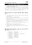
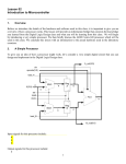
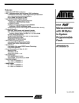
4
Experiment 4 Interrupt and I/O Interfacing
This experiment further consolidates the programmer’s view of computer architecture. It does this
by giving you details of the AVR processor’s interrupt modes and I/O interfacing. This experiment
also shows how you can interface to input/output devices, using interrupts.
4.1
Aim
This experiment aims to:
• Teach you all interrupts supported by AVR.
• Gain experience with interrupt-based AVR assembly language programming.
• Give details of external interrupts and how to service them.
• Show the support that the AVR instruction set architecture has for interfacing to input/output
devices.
• Demonstrate simple and more complex peripherals, as well as the use of timers, keypad, and
LCD display in the microcontroller-based systems.
4.2
Preparation
It is important that you prepare for each laboratory experiment, so that you can use your time (and
your partner’s time) most effectively. For this particular, experiment, you should do the following
before coming in to the Laboratory:
• Read through this experiment in detail, trying to understand what you will be doing.
• Skim-read the section on Programming Style in Experiment 1 and 2.
• Quickly read through the relevant material from your lecture notes for this course.
It is highly recommended that you:
• Type up or modify the necessary files in this experiment, to save time in class, and
• Run through the experiment at home using AVR Studio and AVR Microcontroller Board.
4.3
Save Your Work
The computer in the lab are also used by other students in this course. So when you finish your
lab, please save all your work to your floppy disk and DELETE all files associated with your lab if
you do not want other students to use your files.
4.4
Part 1: Interrupt
Very often we have to react conditions or other events such as change on an input pin. You can
program such a reaction by writing a loop, asking whether a change on the pin has occurred. This
method is called polling. If there are no other things to do and reaction time does not matter, you
can do this with the processor. Otherwise, you need to program an interrupt.
58
In general, an interrupt is a signal generated by an I/O device, or a timer (called hardware interrupt). AVR does not support any instruction to generate a software interrupt. However, programmers can use external interrupts as software interrupts. An interrupt is not handled by CPU
unless the I bit in Program Status Register is set. The relevant instruction that does this is sei.
The AVR provides several different interrupt sources. These interrupts and the separate Reset Vector each have a separate program vector in the program memory space. All interrupts are assigned
individual enable bits which must be written logic one together with the Global Interrupt Enable
bit in the Status Register in order to enable the interrupt.
The lowest addresses in the program memory space are by default defined as the Reset and Interrupt Vectors. The complete list of vectors is shown on the next page.
The list also determines the priority levels of the different interrupts. The lower the address
the higher is the priority level. RESET has the highest priority, and next is INT0, the External
Interrupt Request 0.
When an interrupt occurs, the Global Interrupt Enable I-bit is cleared and all interrupts are
disabled. The user software can write logic one to the I-bit to enable nested interrupts. All enabled
interrupts can then interrupt the current interrupt routine. The I-bit is automatically set when a
Return from Interrupt instruction reti is executed.
There are basically two types of interrupts. The first type is triggered by an event that sets
the interrupt flag. For these interrupts, the Program Counter is vectored to the actual Interrupt
Vector in order to execute the interrupt handling routine, and hardware clears the corresponding
interrupt flag. Interrupt flags can also be cleared by writing a logic one to the flag bit position(s) to
be cleared. If an interrupt condition occurs while the corresponding interrupt enable bit is cleared,
the interrupt flag will be set and remembered until the interrupt is enabled, or the flag is cleared by
software. Similarly, if one or more interrupt conditions occur while the Global Interrupt Enable bit
is cleared, the corresponding interrupt flag(s) will be set and remembered until the Global Interrupt
Enable bit is set, and will then be executed by order of priority.
The second type of interrupts will trigger as long as the interrupt condition is present. These
interrupts do not necessarily have interrupt flags. If the interrupt condition disappears before the
interrupt is enabled, the interrupt will not be triggered. When the AVR exits from an interrupt,
it will always return to the main program and execute one more instruction before any pending
interrupt is served. Note that the Status Register is not automatically stored when entering an
interrupt routine, nor restored when returning from an interrupt routine. This must be handled by
software by push onto or pop from the stack. When using the cli instruction to disable interrupts,
the interrupts will be immediately disabled. No interrupt will be executed after the cli instruction,
even if it occurs simultaneously with the cli instruction. When using the sei instruction to enable
interrupts, the instruction following sei will be executed before any pending interrupts.
The most typical and general program setup for the Reset and Interrupt Vector Addresses in
ATmega64 is shown in Figure 1.
59
Vector No.
1
Program Address
0x0000
Source
RESET
2
3
4
5
6
7
8
9
10
11
12
13
14
15
16
17
18
19
20
21
22
23
24
25
26
27
28
29
30
31
32
33
34
35
0x0002
0x0004
0x0006
0x0008
0x000A
0x000C
0x000E
0x0010
0x0012
0X0014
0X0016
0x0018
0x001A
0x001C
0x001E
0x0020
0x0022
0x0024
0x0026
0x0028
0x002A
0x002C
0x002E
0x0030
0x0032
0x0034
0x0036
0x0038
0x003A
0x003C
0x003E
0x0040
0x0042
0x0044
INT0
INT1
INT2
INT3
INT4
INT5
INT6
INT7
TIMER2 COMP
TIMER2 OVF
TIMER1 CAPT
TIMER1 COMPA
TIMER1 COMPB
TIMER1 OVF
TIMER0 COMP
TIMER0 OVF
SPI, STC
USART0, RX
USART0, UDRE
USART0, TX
ADC
EE READY
ANALOG COMP
TIMER1 COMPC
TIMER3 CAPT
TIMER3 COMPA
TIMER3 COMPB
TIMER3 COMPC
TIMER3 OVF
USART1, RX
USART1, UDRE
USART1, TX
TWI
SPM READY
60
Interrupt Definition
External Pin, Power-on Reset, Brownout Reset, Watchdog Reset, and
JTAG AVR Reset
External Interupt Request 0
External Interupt Request 1
External Interupt Request 2
External Interupt Request 3
External Interupt Request 4
External Interupt Request 5
External Interupt Request 6
External Interupt Request 7
Timer/Counter2 Compare Match
Timer/Counter2 Overflow
Timer/Counter1 Capture Event
Timer/Counter1 Compare Match A
Timer/Counter1 Compare Match B
Timer/Counter0 Overflow
Timer/Counter0 Compare Match
Timer/Counter0 Overflow
SPI Serial Transfer Complete
USART0, Rx Complete
USART0 Data Register Empty
USART0, Tx Complete
ADC Conversion Complete
EEPROM Ready
Analog Comparator
Timer/Counter1 Cmpare Match C
Timer/Counter3 Capture Event
Timer/Counter3 Compare Match A
Timer/Counter3 Compare Match B
Timer/Counter3 Compare Match C
Timer/Counter3 Overflow
USART1, Rx Complete
USART1 Data Register Empty
USART1, Tx Complete
Two-wire Serial Interface
Store Program Memory Ready
0x0000
rjmp
0x0002
rjmp
0x0004
rjmp
0x0006
rjmp
0x0008
rjmp
0x000A
rjmp
0x000C
rjmp
0x000E
rjmp
0x0010
rjmp
0x0012
rjmp
0x0014
rjmp
0x0016
rjmp
0x0018
rjmp
0x001A
rjmp
0x001C
rjmp
0x001E
rjmp
0x0020
rjmp
0x0022
rjmp
0x0024
rjmp
0x0026
rjmp
0x0028
rjmp
0x002A
rjmp
0x002C
rjmp
0x002E
rjmp
0x0030
rjmp
0x0032
rjmp
0x0034
rjmp
0x0036
rjmp
0x0038
rjmp
0x003A
rjmp
0x003C
rjmp
0x003E
rjmp
0x0040
rjmp
0x0042
rjmp
0x0044
rjmp
;
0x0046
RESET:
0x0047
0x0048
0x0049
0x004A
... ... ... ...
RESET
EXT_INT0
EXT_INT1
EXT_INT2
EXT_INT3
EXT_INT4
EXT_INT5
EXT_INT6
EXT_INT7
TIM2_COMP
TIM2_OVF
TIM1_CAPT
TIM1_COMPA
TIM1_COMPB
TIM1_OVF
TIM0_COMP
TIM0_OVF
SPI_STC
USART0_RXC
USART0_DRE
USART0_TXC
ADC
EE_RDY
ANA_COMP
TIM1_COMPC
TIM3_CAPT
TIM3_COMPA
TIM3_COMPB
TIM3_COMPC
TIM3_OVF
USART1_RXC
USART1_DRE
USART1_TXC
TWI
SPM_RDY
ldi
out
ldi
out
sei
;
;
;
;
;
;
;
;
;
;
;
;
;
;
;
;
;
;
;
;
;
;
;
;
;
;
;
;
;
;
;
;
;
;
;
Reset Handler
IRQ0 Handler
IRQ1 Handler
IRQ2 Handler
IRQ3 Handler
IRQ4 Handler
IRQ5 Handler
IRQ6 Handler
IRQ7 Handler
Timer2 Compare Handler
Timer2 Overflow Handler
Timer1 Capture Handler
Timer1 CompareA Handler
Timer1 CompareB Handler
Timer1 Overflow Handler
Timer0 Compare Handler
Timer0 Overflow Handler
SPI Transfer Complete Handler
USART0 RX Complete Handler
USART0,UDR Empty Handler
USART0 TX Complete Handler
ADC Conversion Complete Handler
EEPROM Ready Handler
Analog Comparator Handler
Timer1 CompareC Handler
Timer3 Capture Handler
Timer3 CompareA Handler
Timer3 CompareB Handler
Timer3 CompareC Handler
Timer3 Overflow Handler
USART1 RX Complete Handler
USART1,UDR Empty Handler
USART1 TX Complete Handler
Two-wire Serial Interface Handler
SPM Ready Handler
r16, high(RAMEND) ; Main program start
SPH,r16
; Set Stack Pointer
r16, low(RAMEND)
SPL,r16
; Enable interrupts
Figure 1: Intialization of Interrupt Vectors
61
You do have to setup all the vectors for every program. Figure 2 shows you a small program that
uses external interrupts. Read through the code carefully and try to find out what is happenging,
take note of the instructions when entering and before exiting the interrupt mode.
.include "m64def.inc"
.def temp =r16
.equ HIGH_LEDS
.equ LOW_LEDS
= 0b11110000
= 0b00001111
jmp RESET
.org INT0addr
jmp EXT_INT0
.org INT1addr
jmp EXT_INT1
RESET:
ldi
out
ldi
out
temp, low(RAMEND)
SPL, temp
temp, high(RAMEND)
SPH, temp
ser
out
clr
out
out
out
temp
DDRC, temp
temp
PORTC, temp
DDRD, temp
PORTD, temp
ldi temp, (2 << ISC10) | (2 << ISC00)
sts EICRA, temp
in temp, EIMSK
ori temp, (1<<INT0) | (1<<INT1)
out EIMSK, temp
sei
jmp main
continues on the next page...
62
EXT_INT0:
push temp
in
temp, SREG
push temp
ldi temp, HIGH_LEDS
out PORTC, temp
pop temp
out SREG, temp
pop temp
reti
EXT_INT1:
push temp
in temp, SREG
push temp
ldi temp, LOW_LEDS
out PORTC, temp
pop temp
out SREG, temp
pop temp
reti
; main - does nothing but increment a counter
main:
clr temp
loop:
inc temp
rjmp loop
Figure 2: interrupt.asm
Use the patch cables and connect PB0 to PD0 and PB1 to PD1, also connect PC0-PC7 to LED0LED7. Assemble and download the program onto the AVR Microcontroller Board. The program
can be invoked by press the PB0 and PB1 push button at the bottom right corner of the board.
Be ready to explain your observation to the Laboratory assessor.
4.4.1
Watchdog Timer
The Watchdog Timer (WDT) runs independent of the rest of the system, causing system resets
whenever it times out. However, the application software should ensure that the timeout never
occurs by resetting the WDT periodically as long as the software is in a known healthy state. If
the system hangs or program execution is corrupted, the WDT will not receive its periodic reset,
63
and will eventually time out and cause a system reset.
The WDT in all new AVR devices also has the ability to generate interrupts instead of resetting the device. Since the WDT runs from its own independent clock, it can be used to wake up
the AVR from all sleep modes. This makes it an ideal wakeup timer, easily combined with ordinary
operation as a system reset source. The interrupt can also be used to get an early warning of a upcoming Watchdog System Reset, so that vital parameters can be backed up to non-volatile memory.
When the Watchdog Timer (WDT) period has expired, a WDT timeout occurs. The timeout
period is adjusted using a configurable prescaler, which divides the WDT oscillator clock by a
constant factor. Executing the WDR (Watchdog Reset) instruction resets the timer value. The
application software using the WDT must be designed so that it executes the WDR instruction
periodically whenever it decides that the system still operates correctly. The timer value is automatically reset on system reset and when disabling the WDT.
When using the Watchdog Timer it is important to know that if the Watchdog Always On (WDTON) fuse is programmed, the only possible operation mode is WDT System Reset Mode. This
security feature prevents software from enabling the WDT Interrupt Mode unintentionally, which
could disable the WDT System Reset functionality. When the WDTON fuse is unprogrammed,
the WDT Interrupt Mode can be used.
As mentioned above, the WDT is independent from the rest of the system. It has its own internal oscillator, which runs as long as one of the WDT operating modes is enabled. This ensures
safe operation even if the main CPU oscillator fails. Even if the software designers never intended
to use the WDT, it could be enabled unintentionally, e.g. by a runaway pointer or brown-out
condition. Therefore the startup code should always check the Reset Flags and take appropriate
action if a WDT System Reset has occurred, even if the application does not use the WDT. The
various settings and functions can be combined to use the WDT for different purposes.
Write a program using AVR assembly language that enables the watchdog timer and resets it
in your main program before it generates a RESET interrupt. After 5 seconds has passed, your
program stops resetting the watchdog timer. So the watchdog timer will generate a RESET interrupt. You program should turn all LEDs on when the watchdog timer generates a RESET
interrupt. To know if 5 seconds has passed, you need to use software delay, i.e. executing instructions, instead of using a timer. Read ATMega64 Data Sheet (Pages 54-56) for the details about the
Watchdog Timer. Assemble your program using AVR Studio, and run it on the AVR. Show your
working program to the lab assessor. Remember to save and delete your work before you leave the
laboratory.
Checkpoint 1:
Signature:
Write a program using AVR assembly language that turns on and off every 1 second by using the
Timer 0 Interrupt. Your program should enable the watchdog timer and periodically reset it before
it generates a RESET signal. Read Mega64 Data Sheet for the details about Timer 0. Assemble
your program using AVR Studio, and run it on the AVR Microcontroller Board. Show your working
program to the Laboratory assessor. Remember to save and delete your work before you leave the
laboratory.
64
Checkpoint 2:
4.5
4.5.1
Signature:
Part 2: I/O Interfacing
Keypad
Many applications require driving LEDs along with an interface to a keypad. Implementing such
designs usually involves using up significant amounts of the processors I/O lines. The 4x4 Key
Matrix is can be connected to any of the ports of ATmega64. The keypad sampling is as follows:
1. The columns are connected to output pins, and the rows are connected to input pins.
2. Each column is sequentially driven to a low voltage while at the same instance the four rows
are sampled. Since the rows are all held high with interal pull-up resistors of AVR, all four
inputs will normally be high. If a key is pressed in a column which is at a low level, that low
level will be conducted to the input pin through the closed key and the corresponding row
will be sensed as a low.
3. Before a new column is brought low, care should be taken to discharge the input pins.
In other words, to scan a row, one column output is taken low, and then a row of 4 keys is read.
The row “data” byte (nibble) that has been read is then compared to the 4 values it would have
been had if any of the 4 keys in that row had been pressed. If it matches then that key must have
been pressed. The other rows are then processed similiarly taking each of the 3 outputs low in
turn. (Note: this is a simplistic scanning system and does not allow two keys to be pressed at any
one time).
Figure 3 shows the connection of the 4 × 4 Matrix Keypad:
Figure 3:
Keypad Connections
65
Figure 4 shows the AVR assembly language code for the keypad.
.include "m64def.inc"
rjmp RESET
.def
.def
.def
.def
.def
temp
row
col
mask
temp2
=r16
=r17
=r18
=r19
=r20
.equ
.equ
.equ
.equ
PORTDDIR
INITCOLMASK
INITROWMASK
ROWMASK
=
=
=
=
0xF0
0xEF
0x01
0x0F
RESET:
ldi
out
ldi
out
ldi
out
ser
out
out
temp, low(RAMEND)
SPL, temp
temp, high(RAMEND)
SPH, temp
temp, PORTDDIR
DDRD, temp
temp
DDRC, temp
PORTC, temp
; columns are outputs, rows are inputs
; Make PORTC all outputs
; Turn on all the LEDs
; main - Loops while scanning the keypad to find which key is pressed.
main:
ldi mask, INITCOLMASK
; initial column mask
clr
col
; initial column
colloop:
out
PORTD, mask
; set column to mask value
; (sets column 0 off)
ldi temp, 0xFF
; implement a delay so the
; hardware can stabilize
delay:
dec temp
brne delay
in temp, PIND
andi temp, ROWMASK
cpi temp, 0xF
; read PORTD
; read only the row bits
; check if any rows are grounded
continues on the next page...
66
breq nextcol
ldi mask, INITROWMASK
clr
row
rowloop:
mov temp2, temp
and temp2, mask
brne skipconv
rcall convert
jmp main
skipconv:
inc row
lsl mask
jmp rowloop
nextcol:
cpi col, 3
breq main
sec
rol mask
inc col
jmp colloop
; if not go to the next column
; initialise row check
; initial row
;
;
;
;
;
check masked bit
if the result is non-zero,
we need to look again
if bit is clear, convert the bitcode
and start again
; else move to the next row
; shift the mask to the next bit
; check if we’re on the last column
; if so, no buttons were pushed,
; so start again.
;
;
;
;
;
;
;
else shift the column mask:
We must set the carry bit
and then rotate left by a bit,
shifting the carry into
bit zero. We need this to make
sure all the rows have
pull-up resistors
; increment column value
; and check the next column
; convert function - Converts the row and column given to a binary
; number and also outputs the value to PORTC.
; Inputs come from registers row and col and output is in temp.
convert:
cpi col, 3
breq letters
cpi row, 3
breq symbols
; if column is 3 we have a letter
; if row is 3 we have a symbol or 0
continues on the next page...
67
mov
lsl
add
add
temp, row
temp
temp, row
temp, col
inc temp
;
;
;
;
;
;
;
otherwise we have a number (1-9)
temp = row * 2
temp = row * 3
add the column address
to get the offset from 1
add 1. Value of switch is
row*3 + col + 1.
jmp convert_end
letters:
ldi temp, 0xA
add temp, row
jmp convert_end
symbols:
cpi col, 0
breq star
cpi col, 1
breq zero
ldi temp, 0xF
jmp convert_end
star:
ldi temp, 0xE
jmp convert_end
; increment from 0xA by the row value
; check if we have a star
; or if we have zero
; we’ll output 0xF for hash
; we’ll output 0xE for star
zero:
clr temp
convert_end:
out PORTC, temp
ret
; set to zero
; write value to PORTC
; return to caller
Figure 4: keypad.asm
4.5.2
Liquid Crystal Display
The AVR Microntroller Board comes with a 2 × 16 character Liquid Crystal Display (LCD) module.
This module can be controlled via any of the ATmega64 ports. Below are the pin descriptions.
68
Signal Name
DB4 - DB7
No. of Lines
4
Input/Output
Input/Output
DB0 - DB3
4
Input/Output
BE
1
Input
RS
1
Input
R/W
1
Input
BL
DS
1
1
Input
Input
Function
4 lines of high order data bus.
Bi-directional transfer of data
between MPU and module is
done through these lines. Also
DB7 can be used as a busy
flag. These lines are used as
data in 4 bit operation.
4 lines of low order data bus.
Bi-directional transfer of data
between MPU and module is
done through these lines. In
4 bit operation, these are not
used and should be grounded.
Enable - Operation start signal for data read/write.
Register Select
“0”:
Instruction register
(Write)
: Busy flag; Address counter
(Read)
“1”: Data register (Write,
Read)
Signal to select Read or Write
“0”: Write
“1”: Read
Back light
Data bus buffer enable
In order to write to the LCD, here is the list of things you must satisfy.
Busy Flag
When the busy flag is high or “1” the module is performing an internal operation and the next
instruction will not be accepted. The busy flag outputs to DB7 when RS=0 and a read operation is
performed. The next instruction must not be written until ensuring that the busy flag is low or “0”.
Initialization
The display can be initialized using the internal reset circuit if the Internal Power Supply Reset timing below is met.
69
Figure 5:
Initialization
Note: tof f represents the time of power off condition for a momentary power supply dip or when
cycling power off then on.
If the above conditions are met, the busy flag will go active 10ms after Vcc rises to 4.5V.
Selection of Registers
RS
0
R/W
0
0
1
1
0
1
1
Operation
IR write, internal operation
(display clear etc)
Busy flag (DB7), Address
counter (DB0-DB6) read
DR write, Internal Operation
(DR DD RAM or CG RAM)
DR Read, Internal Operation
(DD RAM or CG RAM)
In general, each character display can be operated in either 4 or 8 bit mode. The next two figures
shows you the steps you must follow to complete the initialization phase. Note: appropriate timing
is very important, when you doing this in software, you have to setup appropriate delay function
to meet the timing constraint.
70
Figure 6:
4-bit Initialization
71
Figure 7:
8-bit Initialization
Instructions/Data are written to the display using the signal timing characteristics found in Figure
8 or Figure 9.
72
Figure 8:
Read from LCD Module Timing Diagram
Figure 9:
Write to LCD Module Timing Diagram
Control and programming the LCD Module correctly and efficiently can be quite complicated
and is beyond the scope of this document. You will need to consult the Optrex Character LCD
Module User’s Manual for more information. You can find this document on the course website.
Write an assembler program called echo.asm which receives an character typed in from the keypad
and prints it on the LCD. When a line is full, start from the beginning of a line. Assemble and
run your program using AVR Studio, download the hex file and show your working program to the
Laboratory assessor. Remember to save and delete your work before you leave the laboratory.
73
Checkpoint 3:
Signature:
Write an assembler program called hex2dec.asm which receive a hex number typed in from the
keypad and print the corresponding decimal number on the LCD. Assemble and run your program
using AVR Studio, download the hex file and show your working program to the Laboratory
assessor. Remember to save and delete your work before you leave the laboratory.
Checkpoint 4:
4.6
4.6.1
Signature:
Part 3 (Optional)
Watchdog System Monitor
Write a program in AVR assembly language satisfying the following requirements.
1. Enables the watchdog timer at the beginning.
2. Turns all LEDs on and off every 1 second by using the Timer 0 Interrrupt.
3. Displays the time in seconds that has passed on LCD.
4. Stops resetting the watchdog timer after 15 seconds has passed.
5. Turn on all LEDs when a RESET is generated.
Assemble your program using AVR Studio and run it on the AVR Microcontroller Board. Show
your working program to the Laboratory assessor. Remember to save and delete your work before
you leave the laboratory.
Checkpoint 4:
Signature:
74