1
Encoder Laboratory
Encode-1
DC Motor with Shaft Encoder
Learning Objectives
By the end of this laboratory experiment, the experimenter should be able to:
•
Explain how an encoder operates and how it can be use determine rotational speed and
angle of a motor shaft
•
Use the IRL520 power MOSFET to control power devices
•
Explain the concept of Pulse-Width Modulation to control the speed of a DC motor
•
Interface the Atmel Atmega 128 microcontroller to an encoder
Components
Qty.
1
1
1
1
1
1
Item
Atmel Atmega 128 microcontroller, STK500 and STK501 interface boards, and serial
port cable.
1M Ω resistors
Solderless breadboard
1N4148 diode
IRL520 power MOSFET
DC motor with encoder
Introduction
In this lab you will investigate how rotational speed and rotational angle can be determined
using a rotary encoder. A rotary encoder consists of a disk with alternating opaque and clear
radial regions. In operation, a light source is positioned on one side of the disk, and a
photosensitive device, such as a phototransistor is positioned on the other side of the disk. As
the disk rotates, the passage of the opaque and clear regions of the encoder disk alternately
block and allow light to impinge on the receiver, which produces corresponding voltage pulses.
The rotational speed of the encoder disk can be determined by counting pulses during a known
time period. The angle of rotation corresponds directly to the number of pulses, since the
number of pulses per revolution is constant.
We will also look at controlling the speed of a DC motor using the concept of Pulse-Width
Modulation (PWM).
Procedure
Function Generator Output to Control Duty Cycle
1. Set up the function generator (FG) to output a 1 kHz square wave (remember to set the
output termination to HIGH Z). Look at the signal on the ‘scope.
2. Set the amplitude to 8 V p-p
3. Offset the waveform by 4 V, so that you have a 0 to 8 V square wave.
4. Select the ‘% Duty’ function on the FG by pressing the Shift key, then the Offset key.
©San José State University Department of Mechanical and Aerospace Engineering
rev. 2.1
06OCT2007
Encoder Laboratory
Encode-2
5. Rotate the knob and see what happens to the output waveform when you vary the duty
cycle. What are the limits you can set the duty cycle to? What does “duty cycle”
mean? Describe in your own words.
DC Motor Speed Contol Using Duty Cycle
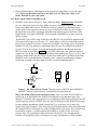
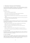
6. Build the circuit shown in Figure 1. Don’t forget the diode. Important note: MOSFET’s
are very sensitive to static electricity. Make sure that you are not carrying static charge
before you handle these devices. It is best to work on a properly grounded anti-static
surface with an anti-static bracelet on your wrist. If these precautions are not available,
then discharge yourself by touching a grounded metal surface (such as the frame of the
bench) before you handle a MOSFET. Always handle a MOSFET by its large metal tab
and by its leads.
The MOSFET you will be using in this lab is the IRL520. It is specifically designed to be
fully turned on by logic-level circuits (5 V), which makes it ideal for controlling medium
power devices, such as dc motors, using a microcontroller. Its package style is an industry
standard TO-220. This package is somewhat awkward to use in a solderless breadboard,
because its leads are so large. To avoid damaging the solderless breadboard, insert the
IRL520 so that its metal tab is parallel to one of the 5-hole rows, but with each lead in a
separate row. To do this, you will have to bend the leads slightly (see Figure 1). The 1 MΩ
resistor is used to make sure that charge can bleed out of the gate to ground to turn off the
MOSFET in the event that the microcontroller pin it connects to inadvertently changes
from being an output (with logic high asserted) to an input (high impedance).
+12 V
1N4148
Motor
D
G
1M
IRL520
IRL520
S
G
S
D
Figure 1. DC Motor Driver Circuit. The circuit uses an IRL520 power MOSFET.
MOSFET’s are very static sensitive, so handle them by the metal tab.
Why is the diode needed across the motor leads? (Note: use of the 1N4148 diode is a
concession to the limitation of the solderless breadboard to accommodate large wire
diameter. It would be more appropriate to use a standard rectifier diode with larger forward
current capacity, such as a 1N4003, however, the lead diameter for the 1N4003 is too large
for the solderless breadboard, which is suited for 22 ga. solid core wire. Leads with
significantly larger diameters when forced into the breadboard holes will permanently bend
the internal contacts. Subsequent use of the breadboard hole with 22 ga. wire can then lead
to unreliable contacts. A work-around to this problem is to solder 22 ga. wire to the
oversize lead. The current draw of the motors used in this lab is low enough that the
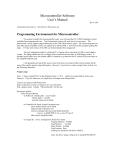
1N4148 will marginally suffice.) See Figure 2 for more information on rectifier diodes.
©San José State University Department of Mechanical and Aerospace Engineering
rev. 2.1
06OCT2007
Encoder Laboratory
Encode-3
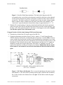
Figure 2. Rectifier Diode Representations. The band on the diagram to the left
corresponds to the vertical line on the schematic symbol for the diode on the right and
can be used to determine the polarity of the diode. A diode acts like a check-valve for
current flow. The diode is said to be ‘forward-biased’ when its anode voltage is higher
than its cathode voltage. (Which lead is the anode, and which is the cathode?) The
‘check-valve’ opens up when the forward-bias voltage is approximately 0.6 V – 1 V.
7. With the FG set up from Step 5, clip the red mini-hook lead from the function generator
cable to the gate of the IRL520 and the black mini-hook lead to the common ground. Vary
the duty cycle of the signal from the FG, and observe what happens to the motor. Explain
why the motor speed varies with the duty cycle.
Using an Encoder with the Atmel Atmega 128 External Interrupt
8. Unhook the red lead of the FG from the gate of the IRL520.
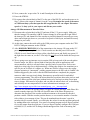
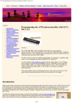
9. Using the information provided in Figure 3 below, connect +5V and Ground from the
STK500 interface board to the corresponding pins of the motor’s encoder (Hint: You may
want to transfer the pins from the encoder to your breadboard by using jumper wires, then
you can easily connect the pins on the Atmega128 to the desired pins of the encoder via the
breadboard.). This will power the encoder’s optointerrupter and provide 0-5V signals on
channels A and B as the encoder wheel turns. Since this is a “quadrature encoder,” the
signals from channels A and B are 90 degrees out of phase. Explain how the two signals
from channel A and channel B can be used to determine the direction that the motor
spins.
Figure 3. DC Motor with Encoder. The view on the right depicts the motor/encoder
from behind (i.e., the motor shaft is pointing into the paper), and from this orientation,
Pin 1 of the encoder is the furthest one to the right. Use the table to make the proper
connections.
©San José State University Department of Mechanical and Aerospace Engineering
rev. 2.1
06OCT2007
Encoder Laboratory
Encode-4
10. Now, connect the ‘scope to the Ch. A and Ground pins of the encoder.
11. Power the STK500.
12. Re-connect the red mini-hook of the FG to the gate of the IRL520, and run the motor as in
Step 7. Observe the output of channel A on the ‘scope. Determine the speed of the motor
at 5 different duty cycles that span the full range that the FG can output. Plot motor
speed vs. % duty cycle in your report, and discuss your results.
Atmega 128 Measurement of Encoder Pulses
13. Disconnect the red mini-hook of the FG and turn off the 12 V power supply. Make sure
that the Atmega 128 controller is OFF. Connect channel A of the encoder to pin PD0 of
the Atmega 128, and channel B of the encoder to pin PB4 (channel B can really go to any
other unused input pin, however you need to keep track of which pin, and make necessary
changes in your code).
14. At this time, connect the serial cable to the COM port on your computer and to the CTRL
RS232 COM port connector on the STK500.
15. After DOUBLE CHECKING all of the connections to the Atmega 128, turn on the 12V
power supply to power up the device. Check to make sure that the power LED on the
STK500 is on (it should turn red, then yellow, then flash green, and finally stay green). If
the light does not come on, see the TA for help. Do not proceed if the board does not power
up!
16. We are going to use an interrupt service routine (ISR) to keep track of the encoder pulses
from the motor. An ISR is a special kind of function often used in applications with
microcontrollers, which is executed when a specific kind of event occurs. Such events
might be a rising edge (low to high transition), a falling edge (high to low transition) on a
specific pin, an overflow of a counter, etc. When one of these events occurs, the regular
program operation is “interrupted”, and the program jumps to the ISR code to “handle” the
situation triggered by the event. After the ISR instructions are completed, the program
returns to what it was previously doing. Interrupts are powerful tools for embedded
systems programming. They allow the microcontroller to perform other tasks (such as send
or receive data across the serial port) without having to be tied up in waiting for an input
state to change. ISRs must be kept short, and care must be taken in their use, so that timing
and reliability are not compromised. For more information on interrupts, see:
http://www.nongnu.org/avr-libc/user-manual/group__avr__interrupts.html
In this lab we will have the encoder Phase A trigger an external interrupt, while Phase B is
routed to another input pin. The ISR will check the state of the Phase B input pin to
determine the direction of the encoder and then increment or decrement the encoder’s
position variable. With the encoder position known, we can count the number of encoder
ticks within a given amount of time. This can be translated into the motor’s speed in
encoder ticks per second. Finally, we will display the values for encoder position and speed
by sending them to the serial port. You can use a terminal program such as HyperTerminal
to view the output from the serial port. If you use HyperTerminal, configure the COM port
to 9600,8,N,1,N, and the ASCII settings should not append line feeds to incoming line
ends.
©San José State University Department of Mechanical and Aerospace Engineering
rev. 2.1
06OCT2007
Encoder Laboratory
Encode-5
17. Now, enter and run the following program. Then open a COM control or HyperTerminal
window.
// Tachometer Program
// Put your name here
// Put the date here
//----- Include Files --------------------------------------------------------#include <avr/io.h>
// include I/O definitions (port names, pin names, etc)
#include <avr/interrupt.h> // include interrupt support
#include "global.h"
// include our global settings
#include "uart.h"
// include uart function library
#include "rprintf.h"
// include printf function library
#include "timer.h"
// include timer function library (timing, PWM, etc)
#include "vt100.h"
// include VT100 terminal support
#define ENC0_A_PORT PORTD
#define ENC0_A_PORTIN PIND
#define ENC0_A_PIN PD0
#define ENC0_A_DDR DDRD
#define ENC0_B_PORT PORTB
#define ENC0_B_PORTIN PINB
#define ENC0_B_PIN PB4
#define ENC0_B_DDR DDRB
//----- Function Declarations-------------------------------------------------void init(void);
s32 position0;
s32 speed0;
//----- Begin Code -----------------------------------------------------------void main(void)
{
s32 startpos;
init();
// initialize everything
vt100ClearScreen();
// clear the terminal screen
// print a little intro message so we know things are working
rprintf("\r\nWelcome to the Wheel Encoder LAB!\r\n");
while(1)
{
startpos = position0;
timerPause(500);
speed0 = (position0 - startpos)*2;
rprintfProgStrM("Encoder0 Position: ");
// print encoder0 position
// use base-10, 10 chars, signed, pad with spaces
rprintfNum(10, 10, TRUE, ' ', position0);
rprintfProgStrM(" Speed: ");
©San José State University Department of Mechanical and Aerospace Engineering
rev. 2.1
06OCT2007
Encoder Laboratory
Encode-6
rprintfNum(10, 10, TRUE, ' ', speed0);
vt100SetCursorPos(5, 1);
}
} // end main()
void init(void)
{
// initialize our libraries
uartInit();
uartSetBaudRate(9600);
timerInit();
rprintfInit(uartSendByte);
vt100Init();
// initialize the UART (serial port)
// set the baud rate of the UART
// initialize the timer system
// initialize rprintf system
// initialize vt100 library
//setup external interrupt
cbi(ENC0_A_PORT, ENC0_A_PIN); //encoder phaseins are inputs with pullups off
cbi(ENC0_B_PORT, ENC0_B_PIN);
EICRA = BV(ISC00)|BV(ISC01); //rising edge triggered
EIMSK = BV(INT0);
//int0 enabled
sei();
}
// end init()
SIGNAL( SIG_INTERRUPT0 )
{
if( ENC0_B_PORTIN & BV(ENC0_B_PIN) ) position0++;
else position0--;
}
Reconnect the red mini-hook of the FG to the gate of the IRL520. Explain how this program
works. Compare the speed you measure with the ‘scope with the value your program
outputs. How well do these values agree?
18. Suppose the encoder were mounted to the shaft of a motor or the wheel of a vehicle. If the
diameter of the wheel is 3 inches, write a program that will indicate the rotational speed of
the wheel and tell how far the vehicle has traveled. How accurately can you calculate the
speed and distance? Quantify your answer.
Run your program with the setup you just used. In order to accomplish this, you may want
to use floating-point math. Yes, the Atmega can handle this! However, to print a floating
point number using rprintf(), you may need to change a small line of code in the
rprintfconf.h header file. This file should be located in the AVRLIB directory on your hard
drive. Uncomment the line that #defines RPRINTF_FLOAT. This will allow the rprintf()
function to print floating point values. See the rprintf.h file and the rprintf example
program included with AVRLIB for help on printing various variable types using rprintf().
©San José State University Department of Mechanical and Aerospace Engineering
rev. 2.1
06OCT2007