1
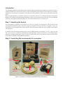
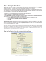
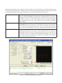
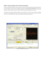
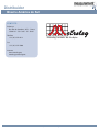
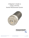
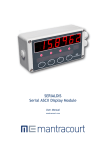
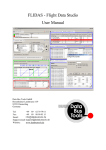
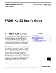
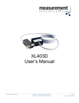
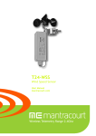
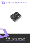
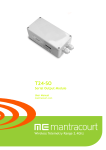
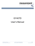
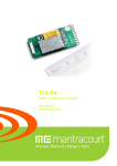
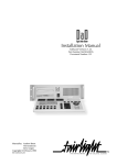
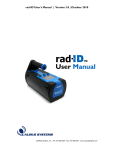
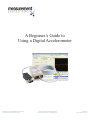
A Beginner’s Guide to
Using a Digital Accelerometer
1A
Beginner’s Guide to Digital Accelerometer
precisionsensors.meas-spec.com 2236 N. Cleveland-Massillon Road
Akron OH 44333 PH : 330-659-3312 8/19/2013
www.meas-spec.com
Introduction
This document guides new users through basic setup of a Measurement Specialties digital accelerometer. The preconfigured nature of this sensor allows users to begin collecting data within minutes of removing the accelerometer
from the box. In the interest of simplicity, only a portion of the capabilities of the sensor will be discussed in this
guide.
More in-depth information is available in the form of Tech Notes, the ICU User’s Manual, and the ICU Reference
Manual, all available on the Measurement Specialties website: precisionsensors.meas-spec.com. For any additional
questions, contact Measurement Specialties, Inc., Precision Inertial Products at 330-659-3312.
Step 1. Unpacking the box(es)
The accelerometer is shipped in a hard plastic case. The case is packed in a shipping box with accessories such
as programming adapters, cables, and power supplies (if ordered) inside the same box (see Image 1 below for
identification of parts included when the PC Interface Kit and mounting adapter are ordered; USB to serial adapter
sold separately).
In addition to the accelerometer and accessories, several additional parts are included. A set of 4 screws in a vial
and a hex wrench are included for attaching the mounting adapter to the accelerometer (see mounting adapter
manual for mounting instructions). There are also two screws and a pair of clips that are used to secure the 9-pin
accelerometer connector to the programming adapter.
Step 2. Connecting the accelerometer to a computer
'LJLWDO$FFHOHURPHWHU
FDEOHGYHUVLRQ
3URJUDPPLQJ
DGDSWHU
0RXQWLQJ
DGDSWHU
0RXQWLQJ
VFUHZV
DQGZUHQFK
$GDSWHUVFUHZV
DQGFOLSV
56FDEOH
3RZHUVXSSO\
IMAGE 1: CONTENTS
OF X5203AK0
(USB ADAPTER SOLD SEPARATELY)
,PDJH
&RQWHQWVRI;$.
Important! Measurement Specialties approves only the use of cables and accessories ordered from the factory. The
use of unapproved cables can irreparably damage the electronics inside the accelerometer.
The following items are the accessories needed to connect a cabled accelerometer to a computer for configuration
or data acquisition purposes. For instructions on configuring a terminal block version, consult the accelerometer
manual included in the shipment.
Included with the PC Interface kit:
Programming Adapter - The programming adapter is a gray box with connectors on both ends. The adapter
converts the RS485 output signal from the sensor into an RS232 signal so the computer can process the
information.
RS232 cable - The RS232 cable connects a computer to the programming adapter. One end of the cable plugs into
the RS232 port on the PC. The other end connects to the programming adapter. Note: If you are connecting
to a laptop or PC with only a USB port, you will need an RS232 to USB adapter.
Power Supply - The power supply plugs into the side of the programming adapter on one end and an electrical
outlet on the other.
Not included with the PC Interface kit:
RS232 to USB Adapter - If the computer has no serial port, a USB adapter is available.
Once the programming adapter, RS232 cable, and power supply are connected as described, you are ready to
configure the digital accelerometer.
IMAGE 2A: SETUP WITH SERIAL PORT
IMAGE 2B: SETUP WITH USB ADAPTER
Step 3. Starting the ICU software
Measurement Specialties provides a software program called Instrument Configuration Utility (ICU) to configure
digital accelerometers. The latest version of ICU and installation instructions are available at
precisionsensors.meas-spec.com. You must install the software on your computer - it cannot be run from the website.
ICU allows users to configure the sensor ranges and PCM stream, and calibrate the instrument. Use the instructions
below to set up ICU to configure and collect data from the instrument.
1. Download ICU software from the website, following the instructions provided.
2. Start the installed ICU software by double clicking the icon.
3. At the About/Setup screen, only two parameters need to be changed from the defaults (click About/Setup button
at the bottom of the screen if you don’t see the screen shown below).
a. Set the Com Port box in the top left corner to the correct location for the computer’s port.
b. Change the Program Function to On-Line Configuration.
c. Click OK.
On-Line Configuration is the mode of operation used most frequently by end users. This interactive mode allows
the user to change sensor settings and collect data via High Speed Acquire. The other modes of operation and their
uses are explained in the ICU User’s Guide.
Note: ICU is designed to configure sensors but does not provide analysis of the data. However, data can be acquired
through ICU for import into Excel, MatLab, and other analysis programs (see Step 7). In addition, Measurement
Specialties provides instructions (via Tech Notes on the website) on how to talk to the accelerometer directly, for
applications which require different software to collect data.
Step 4a. Configuring the data communication settings
Instrument Configuration Utility
Version 2.28
Application Directory: C:\Program Files\ICU
Measurement Specialties, Inc.
2236 N. Cleveland-Massillon Road
Akron, OH 44333
330-659-3312
www.meas-spec.com
1
35203B.def
IMAGE 3: ICU ABOUT/SETUP SCREEN
Click the Configure button in the top left corner of the screen. The software scans for an attached unit. Once a
unit has been identified, ICU reads the configuration data, which is stored in the unit’s nonvolatile memory. The
Configuration screen appears, filled with factory default settings. This section focuses on the Main tab of the OnLine Configuration mode.
# of channels
Encoding
Bit rate
Sync, etc.
Next Page (2)
Up to 4 channels are shown (one for each sensor), however more channels are available. To turn
off some of the channels, select a new number in the Number of Channels box. The highest
numbered channels are removed first, so you may want to rearrange the channels by right clicking
on the channel tabs.
This document will discuss RS485, which is the only bi-directional encoding method to
communicate directly to a PC.
The bit rate controls the speed at which samples are taken. The maximum direct connect speed
via RS232 is 115.38K baud (limited by computer capability).
The six boxes on Page 2 of the telemetry section are for advanced use and the settings are rarely
changed. Sync, S/N, CRC, Frame ID, Pad, Comm ID, and Custom Telemetry allow adjustment
of frame components. See ICU User’s Manual for details.
Note: Adjusting the above settings can increase or decrease the effective sample rate. Viewing the Telemetry report
gives a visual representation of the frame as it is configured. See Step 6 for instructions on viewing reports.
Step 4b. Changing sensor/channel parameters
IMAGE 4: ICU CONFIGURATION SCREEN, MAIN TAB
Each sensor and channel can be configured to meet the needs of a specific application. All of the settings below are
found on individual channel tabs (see image 5 below). Although it may appear complicated, much of the information
is redundant and therefore can be ignored initially. Here are the important fields for first time use:
Filter 3dB Cutoff
Range
Telemetry Word Position
This field controls the filter for each channel. Recommended filter level is 1/10th the
frame rate. When the Bit rate (on the main tab) is changed, the filter level may need
adjustment. If the box is yellow, reduce the filter value until it is at least 10 times
less than the frame rate. Each channel’s filter needs to be changed individually.
Note: Hovering the cursor over a yellow field in ICU will provide an explanation
of the conflict.
You may change the range for each sensor by typing new numbers in the Range Hi
and Range Lo boxes on the sensor’s tab. The ranges are limited by sensor limits and
ICU will warn you by turning the box yellow if you have made a selection outside
of the sensor’s detectible range. Each sensor’s range must be changed individually.
These communication parameters are used in the digital accelerometer for data
encoding and decoding. Set the order of the frame words for each channel by
changing the number in the box. Putting multiple channels on the same data word
can increase or decrease sample rates, but keeping each channel on its own word
is the simplest setup. As a default, each channel will be assigned to one telemetry
word when shipped from the factory.
IMAGE 5: ICU CONFIGURATION SCREEN, CHANNEL TAB
Step 5. Saving settings in the instrument memory
In order to permanently change any settings inside the accelerometer, new values must be written to the instrument’s
non-volatile memory. Once you make a change to a parameter, the Write Values to Instrument button will turn
yellow (see Image 6 below). This is the indication that current ICU settings differ from those saved inside the
instrument. Click on the yellow button to save the current ICU settings in the instrument’s memory.
A password is necessary to complete the changes (“si” is the default - case sensitive). See the ICU User’s Manual
for instructions on changing the password. If you change the password, be sure to store it in a safe place since the
only way to reset the password is to return the accelerometer to Measurement Specialties.
IMAGE 6: ICU SCREEN, SAVING SETTINGS
Step 6. Viewing reports
After making changes to parameters and saving the changes to the instrument, click on the Reports button on the
bottom of the screen to preview the setup. A new screen opens which displays reports based on the parameters you
have saved to the instrument (see Image 7 below).
Click on the Telemetry checkbox at the bottom of the screen to view the data transmission report. This report shows
how the frames will be transmitted and gives sample rates for each channel. If the frames need adjustment, close the
reports screen and make changes to the setup (click on Exit in the Reports screen to return to the ICU Configuration
screen).
Five reports are available for view in ICU (TMATS is not available with RS-485 encoding). Click on the respective
check box to choose a different report.
IMAGE 7: ICU REPORTS SCREEN
Step 7: Acquiring high speed data directly into a PC (using ICU)
In order to take high speed data directly into a computer, ICU provides a High Speed Acquire function. This
function streams data from the instrument at the designated speed and saves it in a .csv file. However, ICU does not
provide a way to analyze or view the data that is acquired. (See Step 3 for instructions on installing ICU software.)
To begin acquiring data:
1. Set the Encoding to RS485
2. Select the correct Bit Rate. (RS232 ports can only accept up to 115.38K baud. RS485 ports can accept up to
1.5Mbit/sec but may be limited to a lower speed by computer capabilities.)
3. Click About/Setup and check the Data Directory that is specified. If the data should be saved in a different
location, specify the new location in the Data Directory box.
4. Ensure you are entering On-Line Configuration mode before leaving the About/Setup screen.
5. Click OK.
6. Click Configure.
7. Click High Speed Acquire button (on the menu bar just above the log) to begin collecting data.
8. When finished, click High Speed Stop. The data will be processed into .csv format. Note: for large files, this
process may take some time.
9. View data by finding the file named for the serial number of the unit with a .csv extension in the location specified
in the Data Directory field (ex. XLT01000.csv).
10. Process and edit data using Excel, MatLab, or other data analysis software.
Problems? Questions? Contact us via email ([email protected]) or phone 330-659-3312.
IMAGE 8: ICU HIGH SPEED ACQUIRE
Copyright © 2002-2013
Measurement Specialties, Inc.
All Rights Reserved
Printing History
Edition 3.0, August 2013
Warranty
Measurement Specialties, Inc. warrants this product against defects in materials and workmanship for a period of
three years from date of shipment. During the warranty period, Measurement Specialties will, at its option, either
repair or replace products which prove to be defective.
Warranty Exclusions
This warranty does not apply to defects or damage resulting from:
• Improper installation or maintenance
• Customer supplied software or interfacing
• Unauthorized modification or misuse
• Operation outside of the product specifications
Limitation of Warranty
The warranty set forth above is exclusive and no other warranty, whether written or oral, is expressed or
implied. Measurement Specialties specifically disclaims the implied warranties of merchantability and fitness
for a particular purpose.
Some jurisdictions do not allow limitations on how long an implied warranty lasts, so the above limitation or
exclusion may not apply to you. However, any implied warranty of merchantability or fitness is limited to the oneyear duration of this written warranty.
Warranty Service
To obtain service during the warranty period, products must be returned, transportation prepaid, to Measurement
Specialties.
Exclusive Remedies
The remedies provided herein are the Buyer’s sole and exclusive remedies. Measurement Specialties shall not
be liable for any direct, indirect, or consequential damages (including lost profit), whether based on warranty,
contract, tort, or any other legal theory.
Restricted Rights
The Software and Documentation have been developed entirely at private expense.They are delivered and
licensed as “commercial computer software”, as a “commercial item”, or as “restricted computersoftware”,
whichever is applicable.
Safety
Do not install substitute parts or perform any unauthorized modification to Measurement Specialties products.
Return the product to Measurement Specialties for service and repair to ensure that safety features are maintained.
Distribuidor
Brasil e América do Sul
C O N TA T O
Ender eço
Rua Sete de Setembro, 2671 - C entro
13560-181 - São C arlos - SP - Brasil
Telefone
+ 55 (16) 3371-0112
Metrolog Controles de Medição
Fax
+ 55 (16) 3372-7800
Inter net
www.metrolog.net
metrolog @ metrolog.net
www.meas-spec.com.br / www.metrolog.net