1
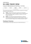
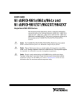
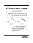
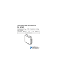
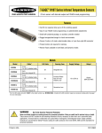
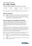
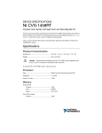
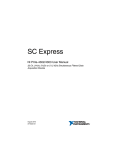
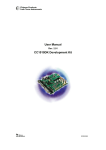
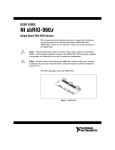
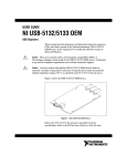
USER MANUAL
NI USB-7845R OEM
R Series for USB Multifunction RIO with Kintex-7 70T FPGA
Français
日本語
Deutsch
한국어
简体中文
ni.com/manuals
This document provides dimensions, connectivity information, and pinouts for the National
Instruments USB-7845R OEM device.
Caution National Instruments makes no product safety, electromagnetic
compatibility (EMC), or CE marking compliance claims for NI USB-7845R OEM
device. The end-product supplier is responsible for conformity to any and all
compliance requirements.
Caution Do not operate the NI USB-7845R OEM device in a manner not specified
in this user manual. Product misuse can result in a hazard. You can compromise the
safety protection built into the product if the product is damaged in any way. If the
product is damaged, return it to National Instruments for repair.
Hardware Overview
The following high-level block diagram represents the NI USB-7845R OEM device.
CONNECTOR 3
Overvoltage
Protection
CONNECTOR 2
Overvoltage
Protection
CONNECTOR 1
Figure 1. NI USB-7845R OEM Device Block Diagram
Overvoltage
Protection
DIO (x16)
Flash
Memory
Data/
Address/
Control
NI ASIC
DIO (x16)
DIO
DIO (x16)
AI (x8)
INA
+5 V
Reference
CONNECTOR 0
Overvoltage
Protection
Overvoltage
Protection
ADC
|
ni.com |
Kintex-7
FPGA
AI
FPGA
Temperature
AO (x8)
DAC
Device
Temperature
2
40 MHz
OSC
NI USB-7845R OEM User Manual
AO
NI USB-7845R OEM
USB
Parts Locator
1
2
3
7
6
8
5
4
1.
2.
3.
4.
USB Connector
Power Supply Connector
Power Switch
External LED Attachments
5.
6.
7.
8.
Connector 0 (Analog)
Connector 1 (Digital)
Connector 2 (Digital)
Connector 3 (Digital)
NI USB-7845R OEM Device Components
The following table lists the interfacing components on the NI USB-7845R OEM device and
the component manufacturers.
Table 1. NI USB-7845R OEM Device Components
Components
Reference Designator
Manufacturer
LEDs
DS2, DS5, DS7, DS8, DS10
SunLED (XZBB54W-1TN)
DS4
Everlight Electronic (QTLP630C-2 T/R)
USB connector
J5
Tyco (292304-1)
Power connector
J1, J2, & J9
Phoenix Contact (1727566)
Power switch
SW2
C&K (E101J1AQE2)
The following table lists and describes the I/O connectors on the NI USB-7845R OEM device.
Refer to the connector manufacturer for information about using and matching these
connectors.
NI USB-7845R OEM User Manual
| © National Instruments |
3
Table 2. NI USB-7845R OEM Device Connectors
4
Connector
Description
Reference Designator
Manufacturer
AI, AO
50-position header
P2
3M (N2550-6002RB)
DIO
34-position header
J9
3M (N2534-6002RB)
External LED
7-position header
E1
FCI 68000-107LF
|
ni.com |
NI USB-7845R OEM User Manual
2X 5.838 (148.29)
3.797 (96.44)
2.055 (52.19)
0.285 (7.24)
Dimensions
2X 6.675 (169.55)
2X 6.435 (163.46)
6.263 (159.08)
2X 6.055 (153.81)
2X 2.863 (72.72)
2X .175 (4.45)
.000 (0)
NI USB-7845R OEM User Manual
6.400 (162.56)
3X 6.115 (155.32)
3X .285 (7.24)
.000 (0)
.119 (3.02)
| © National Instruments |
5
3.812 (96.82)
6.500 (165.1)
2.688 (68.28)
5.830 (148.08)
Note Visit ni.com/dimensions for more information about the dimensions of
the NI USB-7845R OEM device, including two-dimensional drawings and threedimensional models.
Note The NI USB-7845R OEM device has plated mounting holes that can act as
chassis ground.
Connecting the NI USB-7845R OEM Device
The NI USB-7845R OEM device provides connections for eight analog input (AI) channels,
eight analog output (AO) channels, and forty-eight digital input/output (DIO) channels, as
shown in Figure 2.
6
|
ni.com
|
NI USB-7845R OEM User Manual
Figure 2. NI USB-7845R OEM Device Pinout
Connector 1
Connector 0
AI0+
AIGND
AI1+
AIGND
AI2+
AIGND
AI3+
AIGND
AI4+
AIGND
AI5+
AIGND
AI6+
AIGND
AI7+
AIGND
AOGND
AOGND
AOGND
AOGND
AOGND
AOGND
AOGND
AOGND
+5V
1
3
5
7
9
11
13
15
17
19
21
23
25
27
29
31
33
35
37
39
41
43
45
47
49
2
4
6
8
10
12
14
16
18
20
22
24
26
28
30
32
34
36
38
40
42
44
46
48
50
AI0AIGND
AI1AIGND
AI2AIGND
AI3AIGND
AI4AIGND
AI5AIGND
AI6AIGND
AI7AISENSE
AO0
AO1
AO2
AO3
AO4
AO5
AO6
AO7
+5V
DIO0
DIO1
DIO2
DIO3
DIO4
DIO5
DIO6
DIO7
DIO8
DIO9
DIO10
DIO11
DIO12
DIO13
DIO14
DIO15
GND
1 2
3 4
5 6
7 9
9 10
11 12
13 14
15 16
17 18
19 20
21 22
23 24
25 26
27 28
29 30
31 32
33 34
Connector 2
GND
GND
GND
GND
GND
GND
GND
GND
GND
GND
GND
GND
GND
GND
GND
GND
GND
DIO0
DIO1
DIO2
DIO3
DIO4
DIO5
DIO6
DIO7
DIO8
DIO9
DIO10
DIO11
DIO12
DIO13
DIO14
DIO15
GND
1 2
3 4
5 6
7 9
9 10
11 12
13 14
15 16
17 18
19 20
21 22
23 24
25 26
27 28
29 30
31 32
33 34
GND
GND
GND
GND
GND
GND
GND
GND
GND
GND
GND
GND
GND
GND
GND
GND
GND
Connector 3
DIO0
DIO1
DIO2
DIO3
DIO4
DIO5
DIO6
DIO7
DIO8
DIO9
DIO10
DIO11
DIO12
DIO13
DIO14
DIO15
GND
1 2
3 4
5 6
7 9
9 10
11 12
13 14
15 16
17 18
19 20
21 22
23 24
25 26
27 28
29 30
31 32
33 34
GND
GND
GND
GND
GND
GND
GND
GND
GND
GND
GND
GND
GND
GND
GND
GND
GND
Analog Input
The NI USB-7845R OEM device provides connections for eight AI channels. Each channel
has an AI+ pin, AI- pin, and AIGND pin to which you can connect both single-ended or
differential voltage signals. Use the AISENSE pin to connect non-referenced single-ended
signals.
Connecting Single-Ended Voltage Signals
To connect referenced single-ended voltage signals to the NI USB-7845R OEM device, you
must connect the voltage ground signal to AI GND in order to keep the common-mode voltage
in the specified range, as shown in Figure 3.
Figure 3. Connecting Referenced Single-Ended Signals to the NI USB-7845R OEM
Device
V1
+
AI+
Overvoltage
Protection
AI–
Overvoltage
Protection
AISENSE
Overvoltage
Protection
PGIA
ADC
–
AIGND
Connection
Accessory
NI USB-7845R OEM
NI USB-7845R OEM User Manual
| © National Instruments
| 7
To connect non-referenced single-ended voltage signals to the NI USB-7845R OEM device,
you must connect the voltage ground signal to AI SENSE in order to keep the common-mode
voltage in the specified range, as shown in Figure 4.
Figure 4. Connecting Non-Referenced Single-Ended Signals to the NI USB-7845R
OEM Device
AI+
Overvoltage
Protection
AI–
Overvoltage
Protection
AISENSE
Overvoltage
Protection
+
V1
–
PGIA
ADC
+
Vcm
–
AIGND
Connection
Accessory
NI USB-7845R OEM
Connecting Differential Voltage Signals
You can connect grounded or floating differential signal sources to the NI USB-7845R OEM
device. Connect the positive voltage signal to the AI+ and the negative voltage signal to AI-.
To connect grounded differential signals to the NI USB-7845R OEM device, you must also
connect the signal reference to AI GND.
Figure 5. Connecting Grounded Differential Signals to the NI USB-7845R OEM Device
AI+
Overvoltage
Protection
AI–
Overvoltage
Protection
AISENSE
Overvoltage
Protection
+
V1
–
PGIA
ADC
+
Vcm
–
AIGND
Connection
Accessory
NI USB-7845R OEM
To connect floating differential signals to the NI USB-7845R OEM device, you must connect
the negative and positive signals to AI GND through 1 MΩ resistors to keep the voltage within
the common-mode voltage range. If the voltage source is outside the common-mode voltage
range, the NI USB-7845R OEM device does not read data accurately.
8
|
ni.com
|
NI USB-7845R OEM User Manual
Figure 6. Connecting Floating Differential Signals to the NI USB-7845R OEM Device
V1
AI+
Overvoltage
Protection
AI–
Overvoltage
Protection
AISENSE
Overvoltage
Protection
+
–
PGIA
AIGND
Connection
Accessory
ADC
NI USB-7845R OEM
Analog Output
The NI USB-7845R OEM device provides connections for eight analog output channels. Each
channel has an AO pin and AOGND pin to which you can connect a load.
Figure 7. Connecting a Load
DAC
AO
LOAD
AOGND
NI USB-7845R OEM
Connection
Accessory
Digital I/O
The NI USB-7845R OEM device provides connections for 48 digital input/output (DIO)
channels. Connector 1, Connector 2, and Connector 3 contains 16 low-speed channels that can
run up to 10 MHz signal frequencies. Each connector has selectable logic levels that you can
configure as 1.2 V, 1.5 V, 1.8 V, 2.5 V, or 3.3 V. You can configure each channel as input or
output.
NI USB-7845R OEM User Manual
| © National Instruments
| 9
Figure 8. Connecting to the DIO Channels
Connector X/ DIO0
Connector X/ DIO1
1
FPGA
Connector X/ DIO14
Power
Connector X/ DIO15
2
NI USB-7845R OEM
1. Low-speed signal frequencies up to 10 MHz with logic levels configured as 1.2 V, 1.5 V, 1.8 V, 2.5 V, or
3.3 V. Connectors 1 and 2 share the same voltage settings.
2. LED.
The DIO channels connect to the FPGA through buffers, which have overvoltage and
undervoltage protection as well as over current protection. Refer to the NI USB-7845R OEM
Device Specifications for more information about the maximum voltage and current.
When the system powers on, the DIO channels are set as input low with pull-down resistors.
To set another power-on state, you can configure the NI USB-7845R OEM device to load a VI
when the system powers on. The VI can then set the DIO lines to any power-on state.
National Instruments recommends performing signal integrity measurements to test the effect
of signal routing with the cable and connection accessory for your application.
LEDs
If you are putting the NI USB-7845R OEM device in an enclosure, you can either seat the
optional lightpipes on the device or attach external LEDs, as described in the Attaching
External LEDs section. When the lightpipes are attached, the top row is Error, USB Ready,
and POWER LEDs, and the bottom row has the User LEDs.
The NI USB-7845R OEM device has six LEDs which reflect the device state.
Table 3. LED Descriptions
10
|
LED
Description
Location
POWER
Solid blue when the power is on
6
USB READY
Solid blue when the USB is ready
3
ERROR
Solid red for error cases
2
USER1
Blue, user-defined
1
ni.com
|
NI USB-7845R OEM User Manual
Table 3. LED Descriptions (Continued)
LED
Description
Location
USER2
Blue, user-defined
4
USER3
Blue, user-defined
5
Attaching External LEDs
Seven connectors on the device in the E1 part —1, 2, 3, 4, 5, 6, and 7— allow you to connect
an external LED circuit to the device, as shown in Figure 10.
For example, to connect an external USB READY LED, use 7 as the positive connection (+5
V) and 3 and the negative connection.
To connect the remaining LEDs, refer to Table 3.
National Instruments recommends that you limit the current to 10 mA per LED. You can limit
this current by using external resistors, as shown in Figure 9.
Figure 9. External LEDs
OEM (On-Board)
+5 V
1
6
7
External
Resistor
External
LED
Figure 10. Attaching External LEDs
1
2
3
4
5
6
7
NI USB-7845R OEM User Manual
| © National Instruments
| 11
Power Switch
Use the power switch to power the NI USB-7845R OEM device on and off. The following
figure shows the pins on the power switch and power circuitry.
Figure 11. Power Switch (Shown in the On Position)
100 kΩ
to Ground
VDC Out
VDC In
ON
3
2
1
Connector
J8
Switch
SW2
100 kΩ
1
2
NC
ON
NC
Power to
Device
SW2
F1
21
3
100 kΩ
J8
2
1
Power
Connector
The following table lists the pin locations and signal descriptions.
Table 4. Power Switch Pin Descriptions
Pin
Signal
Description
1
VDC In
Connects to VDC through a non-user replaceable fuse (reference
designator F1). The VDC is the voltage provided by the power supply
through pin 2 of the power connector (reference designator J8) and
must be 9 V to 30 V, 20 W.
2
VDC Out
Provides power to the circuitry on the NI USB-7845R OEM device.
When the switch is in the on position, the VDC power supply from pin
1 is routed to pin 2.
3
100 kΩ to
Ground
Connects pin 2 to ground through a 100 kΩ resistor when the switch is
in the off position.
+5 V Power Source
Use the +5 V terminals on the I/O connector supply +5 V referenced to DGND to power
external circuitry.
Caution Never connect the +5 V power terminals to analog or digital ground or
any other voltage source on the NI USB-7845R OEM device or any other device.
12 |
ni.com |
NI USB-7845R OEM User Manual
Doing so can damage the device and the computer. National Instruments is not liable
for damage resulting from such a connection.
The power rating is 4.75 to 5.1 VDC at 0.5 A.
Autonomous Mode
You can run the NI USB-7845R OEM device without a USB connection to a host computer
using Autonomous Mode. To collect data the NI USB-7845R OEM device acquires in
Autonomous Mode, you must reconnect the NI USB-7845R OEM device to a host computer.
Caution Data is lost and is not recoverable upon reconnection if a DMA FIFO
overflows while the NI USB-7845R OEM device is disconnected from the host
computer or if the NI USB-7845R OEM device loses power at any point.
Autonomous Mode includes the following capabilities.
Table 5. Autonomous Mode Capabilities
Capability
Description
Use the Open/Close FPGA
Reference VI functions to
run an FPGA VI and then
disconnect the USB cable.
Call the Close FPGA VI Reference Function without aborting
or resetting the FPGA VI before you disconnect the USB
cable.1
After you disconnect the USB cable, any VI running on the
NI USB-7845R OEM device continues to run and collect data,
which can later be retrieved by reconnecting the USB cable
and re-opening the original FPGA reference.
Use Interactive Front Panel
Communication to run an
FPGA VI and then
disconnecting the USB
cable.
The front panel indicators stop updating.
After you disconnect the USB cable, any VI running on the
NI USB-7845R OEM device continues to run. Restore the
Interactive Front Panel Communication by reconnecting the
USB cable.
Download the bitfile to
flash memory and set it to
run when loaded to FPGA.
Download the bitfile to flash memory and set it to run when
loaded to FPGA. The bitfile automatically starts running
whenever power is applied to the
NI USB-7845R OEM device. To collect data, you must
reconnect the NI USB-7845R OEM device to a host computer
before powering off the device.
Refer to the LabVIEW FPGA Module Help for more
information about downloading an FPGA VI to the flash
memory.
1
The Host VI errors out if you do not call the Close FPGA VI Reference Function without aborting
or resetting the FPGA VI.
NI USB-7845R OEM User Manual
| © National Instruments
| 13
Worldwide Support and Services
The National Instruments website is your complete resource for technical support. At ni.com/
support, you have access to everything from troubleshooting and application development
self-help resources to email and phone assistance from NI Application Engineers.
Visit ni.com/services for NI Factory Installation Services, repairs, extended warranty, and
other services.
Visit ni.com/register to register your National Instruments product. Product registration
facilitates technical support and ensures that you receive important information updates from
NI.
National Instruments corporate headquarters is located at 11500 North Mopac Expressway,
Austin, Texas, 78759-3504. National Instruments also has offices located around the world.
For telephone support in the United States, create your service request at ni.com/support or
dial 1 866 ASK MYNI (275 6964). For telephone support outside the United States, visit the
Worldwide Offices section of ni.com/niglobal to access the branch office websites, which
provide up-to-date contact information, support phone numbers, email addresses, and current
events.
Refer to the NI Trademarks and Logo Guidelines at ni.com/trademarks for information on National Instruments trademarks.
Other product and company names mentioned herein are trademarks or trade names of their respective companies. For patents
covering National Instruments products/technology, refer to the appropriate location: Help»Patents in your software, the
patents.txt file on your media, or the National Instruments Patent Notice at ni.com/patents. You can find information about
end-user license agreements (EULAs) and third-party legal notices in the readme file for your NI product. Refer to the Export
Compliance Information at ni.com/legal/export-compliance for the National Instruments global trade compliance policy and
how to obtain relevant HTS codes, ECCNs, and other import/export data.
© 2014 National Instruments. All rights reserved.
374508A-01
Mar14