1
Q3X Laser Contrast Sensor
Instruction Manual
Original Instructions
181485 Rev. D
15 July 2015
181485
Q3X Laser Contrast Sensor
Contents
1 Product Description
........................................................................................................ 3
1.1 Models
....................................................................................................................................3
1.2 Overview
................................................................................................................................ 3
1.3 Features
................................................................................................................................. 4
1.3.1 Display and Indicators
......................................................................................................4
1.3.2 Buttons
......................................................................................................................... 5
1.4 Laser Description and Safety Information
.................................................................................... 5
2 Installation
2.1
2.2
2.3
2.4
2.5
2.6
..................................................................................................................... 7
Install the Safety Label
............................................................................................................. 7
Sensor Orientation
................................................................................................................... 7
Sensor-to-Background Position
.................................................................................................. 7
Sensor Mounting
...................................................................................................................... 7
Wiring Diagram
........................................................................................................................8
Cleaning and Maintenance
.........................................................................................................8
3 Sensor Programming
..................................................................................................... 9
3.1 Setup Mode
.............................................................................................................................9
3.1.1 Output Operation
........................................................................................................... 9
3.1.2 TEACH Menu
..................................................................................................................9
3.1.3 Offset Percentage
........................................................................................................... 9
3.1.4 Response Speed
........................................................................................................... 10
3.1.5 Output Timing Delays
....................................................................................................10
3.1.6 Input Wire Function
...................................................................................................... 11
3.1.7 Sensitivity
................................................................................................................... 12
3.1.8 Cut-Off Operation
......................................................................................................... 12
3.1.9 Display View
................................................................................................................ 12
3.1.10 Exit the Top Menu
....................................................................................................... 12
3.1.11 Reset to Factory Defaults
............................................................................................. 13
3.2 Manual Adjustments
............................................................................................................... 13
3.3 Remote Input
........................................................................................................................ 13
3.3.1 Select the TEACH mode using the Remote Input
............................................................... 14
3.3.2 Reset to Factory Defaults Using the Remote Input
.............................................................15
3.4 Locking and Unlocking the Sensor Buttons
.................................................................................. 15
3.5 TEACH Procedures
.................................................................................................................. 16
3.5.1 Detection Reliability
...................................................................................................... 16
3.5.2 Two-Point Static TEACH
................................................................................................. 16
3.5.3 Dynamic TEACH
............................................................................................................17
3.5.4 Window Set
................................................................................................................. 19
3.5.5 Light Set
..................................................................................................................... 20
3.5.6 Dark Set
......................................................................................................................21
3.6 Sync Master/Slave
..................................................................................................................22
3.7 Sensor Menu Map
....................................................................................................................23
4 Specifications
.............................................................................................................. 24
4.1 Performance Curves
............................................................................................................... 25
4.2 Dimensions
........................................................................................................................... 26
5 Abbreviations
.............................................................................................................. 27
6 Troubleshooting
...........................................................................................................29
7 Accessories
...................................................................................................................30
7.1 Cordsets
7.2 Brackets
............................................................................................................................... 30
............................................................................................................................... 30
8 Contact Us
................................................................................................................... 32
9 Banner Engineering Corp Limited Warranty
................................................................. 33
Q3X Laser Contrast Sensor
1 Product Description
Laser Expert™ diffuse sensor with bipolar (1 PNP & 1 NPN) output. Patent pending.
•
•
•
•
•
•
•
•
Solves challenging part-detection applications with small contrast
differences
High-speed part detection as fast as 250 µs, capturing up to 2,000
events per second
Some models with background suppression allow reliable contrast
detection with changing background conditions
Angled three-digit display is easily viewed from multiple vantage
points
Display provides clear user feedback for easy setup, and bright output
indicator provides high visibility of sensor operation
Intuitive setup utilizing two tactile buttons located below the display
Rugged nickel-plated zinc, laser-marked housing suitable for use even
in environments where cutting fluids and oils might be present
Robust immunity to fluorescent light interference
WARNING: Not To Be Used for Personnel Protection
Never use this device as a sensing device for personnel protection. Doing so could lead to
serious injury or death. This device does not include the self-checking redundant circuitry necessary
to allow its use in personnel safety applications. A sensor failure or malfunction can cause either an
energized or de-energized sensor output condition.
1.1 Models
Contrast Sensing
Range
Background
Suppression Distance
0 to 300 mm (11.81 in)
Not Applicable
0 to 50 mm (1.97 in)
60 mm (2.36 in)
Q3XTBLD100-Q8
0 to 100 mm (3.94 in)
120 mm (4.72 in)
Q3XTBLD150-Q8
0 to 150 mm (5.91 in)
190 mm (7.48 in)
Q3XTBLD200-Q8
0 to 200 mm (7.87 in)
280 mm (11.02 in)
Model
Q3XTBLD-Q8
Q3XTBLD50-Q8
Output Type
Connection
Bipolar: 1 NPN, 1 PNP
5-pin M12 Euro-style
integral connector
1.2 Overview
The Q3X Sensor is an Expert™ laser diffuse contrast sensor for low contrast detection application. Some models of the Q3X
are able to ignore targets beyond a factory-set background suppression distance. This innovative combination of low
contrast diffuse sensing of targets while ignoring objects beyond the region of interest eliminates the biggest problem of
diffuse mode sensing, namely changing background conditions affecting the contrast detection.
The normal sensor state is Run mode. From Run mode, the switch point value can be changed and the selected TEACH
method can be performed. The secondary sensor state is Setup mode. From Setup mode, the TEACH mode can be
selected, all standard operating parameters can be adjusted, and a factory reset can be done.
www.bannerengineering.com - Tel: 763.544.3164
3
Q3X Laser Contrast Sensor
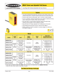
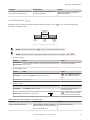
1.3 Features
1
2
1. Output Indicator (Amber)
2. Display
3. Buttons
3
Figure 1. Sensor Features
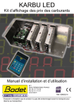
1.3.1 Display and Indicators
1. Stability Indicator (STB = Green)
2. Active TEACH Indicators
• DYN = Dynamic TEACH selected (Amber)
• WND = Symmetric window thresholds are
active (Amber)
Figure 2. Display in Run Mode
In Run mode, the 3-digit, 7-segment display provides real time information about signal strength for all models and target
position for models with a fixed background suppression distance. The numeric value of 0 to 990 represent the amount of
the received light divided by the threshold, and represents the excess gain of the sensing event expressed as a percentage
of the switch point. This value is called normalized signal strength (NSS). A NSS display range of 999 indicates a saturated
received light signal, meaning that low contrast detection is not possible.
In single threshold teach modes (Two-Point Static, Dynamic, Light Set, or Dark Set), the output switches at a displayed
value of 100 (excess gain of 1.0).
For models with a specified background suppression distance,
indicates that a target is present at a distance beyond
the background suppression distance and is being suppressed. In Light Operate mode, the output switches off when
displays. For the LD50 models, the sensor's output state when displaying
can be controlled using the
By default, the sensor treats a target in the background as a dark signal and honors the LO/DO selection.
A displayed value of
menu.
indicates no light received or a loss of signal.
In Window Set teach mode, the value 100 represents the taught signal strength. The displayed value is the percentage of
the received light divided by the taught signal strength. The output switches at displayed values above and below 100 as
determined by the user-selected window offset percentage.
Output Indicator
•
•
On—Outputs conducting (closed)
Off—Outputs not conducting (open)
Stability Indicator (STB)
•
•
•
4
On—Stable light signal received
Flashing—Light intensity is within the switching threshold hysteresis band
Off—No light signal received
www.bannerengineering.com - Tel: 763.544.3164
Q3X Laser Contrast Sensor
Active TEACH Indicators (DYN and WND)
•
•
•
•
DYN and WND off—Two-Point Static , Light Set, or Dark Set TEACH mode selected (Two-Point Static TEACH is the
default).
DYN and/or WND flashing—The sensor is in TEACH mode.
DYN on—Dynamic TEACH mode selected
WND on—Symmetric Window thresholds are active. The switch points are above and below 100 by the offset
percentage
1.3.2 Buttons
Use the sensor buttons (-)(MODE) and (+)(TEACH) to program the sensor.
See Sensor Programming on page 9 for programming instructions.
(-)(MODE)
•
•
•
•
Decrease gain: press and release (-)(MODE), then press and hold (-)(MODE) to rapidly decrease gain
Enter Setup mode: press and hold (-)(MODE) for longer than 2 seconds
Navigate the sensor menu: press (-)(MODE)
Change setting values: press and hold (-)(MODE) to decrease numeric values
(+)(TEACH)
•
•
•
•
Increase gain: press and release (+)(TEACH), then press and hold (+)(TEACH) to rapidly increase gain
Start the currently selected TEACH mode: press and hold (+)(TEACH) for longer than 2 seconds (Two-Point Static
TEACH is the default)
Navigate the sensor menu: press (+)(TEACH)
Change setting values: press and hold (+)(TEACH) to increase numeric values
(-)(MODE) and (+)(TEACH)
•
•
Select menu items in Setup mode: press (-)(MODE) and (+)(TEACH) simultaneously
Select and save a parameter and return to Run mode: press (-)(MODE) and (+)(TEACH) simultaneously for
longer than 2 seconds
When navigating the menu systems, the menu items loop.
1.4 Laser Description and Safety Information
For Safe Laser Use - Class 2 Lasers
• Do not stare at the laser.
• Do not point the laser at a person’s eye.
• Mount open laser beam paths either above or below eye level, where practical.
• Terminate the beam emitted by the laser product at the end of its useful path.
CAUTION: Use of controls or adjustments or performance of procedures
other than those specified herein may result in hazardous radiation
exposure. Do not attempt to disassemble this sensor for repair. A defective
unit must be returned to the manufacturer.
CAUTION: Never stare directly into the sensor lens. Laser light can damage your eyes. Avoid
placing any mirror-like object in the beam. Never use a mirror as a retroreflective target.
www.bannerengineering.com - Tel: 763.544.3164
5
Q3X Laser Contrast Sensor
Class 2 Lasers
Class 2 lasers are lasers that emit visible radiation in the wavelength range from 400 nm to 700 nm, where eye
protection is normally afforded by aversion responses, including the blink reflex. This reaction may be expected to
provide adequate protection under reasonably foreseeable conditions of operation, including the use of optical
instruments for intrabeam viewing.
Class 2 Laser Safety Notes
Low-power lasers are, by definition, incapable of causing eye injury within the duration of a blink (aversion response) of
0.25 seconds. They also must emit only visible wavelengths (400 to 700 nm). Therefore, an ocular hazard may exist only
if individuals overcome their natural aversion to bright light and stare directly into the laser beam.
Laser wavelength: 655 nm
Output: < 0.42 mW
Pulse Duration: 5 µs
6
www.bannerengineering.com - Tel: 763.544.3164
Q3X Laser Contrast Sensor
2 Installation
2.1 Install the Safety Label
The safety label must be installed on Q3X sensors that are used in the
United States.
NOTE: Position the label on the cable in a location that
has minimal chemical exposure.
1. Remove the protective cover from the adhesive on the label.
2. Wrap the label around the Q3X cable, as shown.
3. Press the two halves of the label together.
Figure 3. Safety Label Installation
2.2 Sensor Orientation
Correct sensor-to-target orientation is important to ensure proper
sensing. To ensure reliable detection, orient the sensor as shown
in relation to the target to be detected.
For models with background suppression, make sure the intended
target is inside of the contrast sensing range and that any
background objects are positioned beyond the background
suppression distance.
Figure 4. Optimal Orientation of Target to Sensor
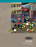
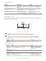
2.3 Sensor-to-Background Position
Target
Background
X = Diffuse Sensing Range
X
Y
Y = Recommended
Background
Distance
Model Number
X
Y
LD50
50 mm (1.97 in)
60 mm (2.36 in)
LD100
100 mm (3.94 in)
120 mm (4.72 in)
LD150
150 mm (5.91 in)
190 mm (7.48 in)
LD200
200 mm (7.87 in)
280 mm (11.02 in)
Figure 5. Q3XBLD Contrast Detection versus Background Suppression
2.4 Sensor Mounting
1. If a bracket is needed, mount the sensor onto the bracket.
2. Mount the sensor (or the sensor and the bracket) to the machine or equipment at the desired location. Do not
tighten at this time.
3. Check the sensor alignment.
4. Tighten the screws to secure the sensor (or the sensor and the bracket) in the aligned position.
www.bannerengineering.com - Tel: 763.544.3164
7
Q3X Laser Contrast Sensor
2.5 Wiring Diagram
1
+
10-30V dc
–
3
2
4
5
1
2
4
5
3
Load
Load
Key
Input
Wire
NOTE: Open lead wires must be connected to a terminal block.
1
2
3
4
5
=
=
=
=
=
Brown
White
Blue
Black
Gray
NOTE: The input wire function is user-selectable. The default for the input wire function is off
(disabled).
2.6 Cleaning and Maintenance
Handle the sensor with care during installation and operation. Sensor windows soiled by fingerprints, dust, water, oil, etc.
may create stray light that may degrade the peak performance of the sensor. Blow the window clear using filtered,
compressed air, then clean as necessary using 70% isopropyl alcohol and cotton swabs or water and a soft cloth.
8
www.bannerengineering.com - Tel: 763.544.3164
Q3X Laser Contrast Sensor
3 Sensor Programming
Program the sensor using the buttons on the sensor or the input wire (limited programming options; see Remote Input on
page 13 for details).
In addition to programming the sensor, use the input wire to disable the buttons for security, preventing unauthorized or
accidental programming changes. See Locking and Unlocking the Sensor Buttons on page 15 for more information.
3.1 Setup Mode
1. Access Setup mode from Run mode by pressing and holding MODE for longer than 2 seconds.
2. Use
or
to navigate through the top menu.
3. Select the desired submenu by pressing
and
simultaneously.
4. Press
or
to view the available options in the submenu.
5. Select a submenu option.
•
Press
•
Press
and
simultaneously for longer than 2 seconds to select and save a submenu option and
return to Run mode.
and
simultaneously to select and save a submenu option and return to the top menu.
NOTE: The current submenu selection is solid, all other selections flash.
To exit Setup mode from the top menu and return to Run mode, navigate to
simultaneously, or press and hold
anywhere in the top menu.
and
and press
and
simultaneously for longer than 2 seconds to return to Run mode from
3.1.1 Output Operation
Use this menu to select the output operation mode. The default is light operate.
•
—Light operate. The output is on when the sensor detects a light state
•
—Dark operate. The output is on when the sensor detects a dark state
3.1.2 TEACH Menu
Use this menu to select the TEACH mode. The default is two-point static TEACH mode.
•
•
—Two-point static TEACH
—Dynamic TEACH
•
—Window set
•
—Light set
•
—Dark set
After the TEACH mode is selected, from Run mode, press and hold TEACH for longer than 2 seconds to access the TEACH
mode and teach the sensor. See TEACH Procedures on page 16 for additional information and remote input TEACH
instructions.
When Window set, Light set, or Dark set are selected, the sensor returns to the Setup menu and the Offset Percentage
menu (
) becomes available to set the offset percentage.
3.1.3 Offset Percentage
Use this menu to select the offset percentage when Window set, Light set, or Dark set TEACH modes are selected. The
default is 20% for Window and Light Set, and 50% for Dark Set.
Window and Light Set options:
www.bannerengineering.com - Tel: 763.544.3164
9
Q3X Laser Contrast Sensor
•
—minimum
•
—10%
•
—20%
•
—30%
•
—40%
•
—50%
Dark Set options:
•
—minimum
•
—25%
•
—50%
•
—100%
•
—200%
3.1.4 Response Speed
Use this menu to select the response speed. The default is 1 millisecond.
•
—250 microseconds
•
—1 millisecond
•
—5 milliseconds
Table 1: Tradeoffs
Response Speed
Repeatability
Crosstalk Immunity
High Efficiency Light Rejection
250 µs
60 µs
Disabled
Disabled
1 ms
300 µs
Enabled
Disabled
5 ms
520 µs
Enabled
Enabled
25 ms (Master-Slave Sync)
13 ms
Best for direct line of sight
crosstalk
Enabled
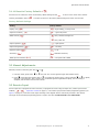
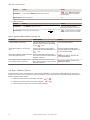
3.1.5 Output Timing Delays
Use this menu to select the output timing delay to be set. Only one delay type can be used at a time. The default is no
delay.
•
—No delay
•
—Enables simultaneous on and off delay timers
•
10
—One-shot. Enables a one-shot, fixed output pulse duration
www.bannerengineering.com - Tel: 763.544.3164
Q3X Laser Contrast Sensor
ON
Output
OFF
D
OFF Delay
D
ON Delay
D
D
1-Shot
D
D
Time
(D = 1ms - 90.0s)
Figure 6. Output Timing Delays
When either
set the timer(s):
•
•
•
or
is chosen, the sensor returns to the Setup menu and additional options become available to
—On delay
—Off delay
—Delay timer
NOTE: For the one-shot timer:
• LO = On pulse when a target is detected in the light state
• DO = On pulse when a target is detected in the dark state
Delay Timer
,
,
Use these menus to set the delay timers. These menus are only available if an output timing delay is selected.
• 1 to 9 ms in 1 ms increments
• 10 to 90 ms in 10 ms increments
• 100 to 900 ms in 100 ms increments
• 1.0 to 90.0 s in 1.0 s increments
For
and
For
•
•
, the default is 0.
, the default is:
1 ms when the response speed is either 250 µs or 1 ms
10 ms when the response speed is 5 ms
Use
or
to scroll through the values. Millisecond values do not include the decimal point; seconds values include the
decimal point.
3.1.6 Input Wire Function
Use this menu to select the input wire function. The default is off.
•
•
•
•
—Ignore all pulses
—Laser off when pulled low
—Remote TEACH input
—Master sync line output for two-sensor cross-talk avoidance
www.bannerengineering.com - Tel: 763.544.3164
11
Q3X Laser Contrast Sensor
•
—Slave sync line output for two-sensor cross-talk avoidance
To configure sensors for master-slave operation, see Sync Master/Slave on page 22.
3.1.7 Sensitivity
Use this menu to set the sensitivity. The default is standard.
•
—High sensitivity. Use this setting for low contrast sensing
•
—Standard sensitivity
•
—Low sensitivity. Use this setting to stabilize the output in high vibration applications
3.1.8 Cut-Off Operation
Use this menu to select cut-off operation. The default is
•
— Output follows LO/DO selection; sensor treats target in background (or loss of signal) as the dark state.
•
— Output switches OFF when the target is beyond the background suppression distance.
•
— Output switches ON when the target is beyond the background suppression distance.
Table 2: Cut-off output settings and operation
Output State Based on
menu and LO/DO Selections
Target in Cut-Off
No Light Received (Loss of Signal)
LO/DO
LO/DO
OFF
LO/DO
ON
LO/DO
NOTE: The output may transition ON to OFF or OFF to ON when the target enters the diffuse sensing
range. Consider an ON-Delay or the laser inhibit input if necessary.
3.1.9 Display View
Use this menu to select the display view. The default is right-reading.
•
—Right-reading
•
—Inverted
•
—Right-reading and the display enters sleep mode after 60 seconds
•
—Inverted and the display enters sleep mode after 60 seconds
When the sensor is in sleep mode, the display wakes with the first button press.
3.1.10 Exit the Top Menu
Navigate to
and press TEACH and MODE together to exit the top menu and return to Run mode.
Setup mode can also be exited by pressing and holding
anywhere in the top menu.
12
and
simultaneously for longer than 2 seconds from
www.bannerengineering.com - Tel: 763.544.3164
Q3X Laser Contrast Sensor
3.1.11 Reset to Factory Defaults
Use this menu to restore the sensor to the factory default settings. Select
to return to the sensor menu without
to restore the sensor to the factory default settings and return to Run mode.
restoring the defaults. Select
Factory Default Settings
Setting
Factory Default
Display view (
)
—Right-reading, no sleep mode
Input wire function (
)
—Ignore all pulses
)
Offset Percent (
—20%, Window and Light Set
—50%, Dark Set
Output operation (
)
Output timing delays (
Response speed (
Sensitivity (
—Light operate
)
—No delay
)
—1 ms
)
TEACH process selection (
—Standard sensitivity
)
—Two-point static TEACH
3.2 Manual Adjustments
Manually increase or decrease gain using
1. From Run mode, press either
or
or
.
one time. The current signal strength value flashes slowly.
to decrease the sensor's gain or
to increase the sensor's gain, or press and hold
or
to rapidly
2. Press
decrease or increase gain. After 1 second, the normalized signal strength flashes rapidly, the new setting is
accepted, and the sensor returns to Run mode.
3.3 Remote Input
Use the input wire to program the sensor remotely. To program the sensor using the input wire, remote input must be
enabled (
=
, Input Wire Function on page 11). The remote input provides limited programming options (see
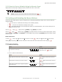
Figure 7 on page 14). Pulse the remote input according to the diagram and the instructions provided in this manual.
The length of the individual programming pulses is equal to the value T: 0.04 seconds ≤ T ≤ 0.8 seconds.
www.bannerengineering.com - Tel: 763.544.3164
13
Q3X Laser Contrast Sensor
= Set
(gray wire is input wire)
REMOTE
TEACH
Remote
Input
Pulse Timing (T)
0.04 seconds < T < 0.8 seconds
Timing between Pulse groups > 1 second
Starts selected Teach (same function as pressing Teach Button for > 2 sec)
1x
Second pulse completes Teach (Two-point and Dynamic Teach only)
1x
Teach Selection
2x
Two-point static background suppression
REMOTE SETUP
1x
2x
Dynamic background suppression
3x
One-point window set
4x
One-point light set
5x
One-point dark set
Button Lock
4x
1x
Button Unlock
2x
Button Lock
Operator Lock
3x
Reset to Factory Defaults (maintains remote input = SET)
8x
Figure 7. Remote Input Map
3.3.1 Select the TEACH mode using the Remote Input
1. Access the TEACH selection.
Action
Result
T
Double-pulse the remote input.
T
T
displays.
2. Select the desired TEACH mode.
Action
Result
Pulses
1
2
3
4
5
14
TEACH Mode
T
Two-point static TEACH
T
T
Dynamic TEACH
T
T
T
T
T
T
T
T
T
T
T
T
T
T
T
One-point window set
T
T
One-point light set
T
T
T
T
T
One-point dark set
www.bannerengineering.com - Tel: 763.544.3164
The selected TEACH method displays for a
few seconds and the sensor returns to Run
mode.
Q3X Laser Contrast Sensor
3.3.2 Reset to Factory Defaults Using the Remote Input
Eight-pulse the remote input to apply the factory defaults and return to Run mode.
T
T
T
T
T
T
T
T
T
T
T
T
T
T
T
NOTE: The input wire function remains at remote teach input (
).
3.4 Locking and Unlocking the Sensor Buttons
Use the lock and unlock feature to prevent unauthorized or accidental programming changes. There are three different
settings available:
•
—The sensor is unlocked and all settings can be modified (default).
—The sensor is locked and no changes can be made.
•
•
—The switch point value can be changed by teaching or manual adjustment, but no sensor settings can be
changed through the menu.
mode,
When in
displays when (-)(MODE) or (+)(TEACH) are pressed.
When in
mode,
displays when (-)(MODE) is pressed and held. To access the manual adjust options, briefly
press and release (-)(MODE) or (+)(TEACH). To enter TEACH mode, press the (+)(TEACH) button and hold for longer
than 2 seconds.
Button Instructions
mode, hold
To enter
Holding
and pressing
and press
four times. To enter
mode, hold
and press
seven times.
four times unlocks the sensor from either lock mode and the sensor displays
.
Remote Input Instructions
1. Access the remote input.
Action
Result
T
Four-pulse the remote input.
T
T
T
T
T
T
The sensor is ready to have the button
state defined and
displays.
2. Lock or unlock the sensor buttons.
Action
Result
Single-pulse the remote input to unlock the sensor.
Double-pulse the remote input to lock the sensor.
Triple-pulse the remote input to apply the operator
lock to the sensor.
T
displays and the sensor returns to
Run mode.
T
T
displays and the sensor returns to
Run mode.
T
T
T
T
T
T
www.bannerengineering.com - Tel: 763.544.3164
displays and the sensor returns to
Run mode.
15
Q3X Laser Contrast Sensor
3.5 TEACH Procedures
3.5.1 Detection Reliability
After completing a TEACH, the detection reliability of the application can be assessed by comparing the displayed NSS
value of the light and dark target conditions. The difference between the two displayed values is an indication of the
contrast of the application.
Difference between Light and Dark target NSS values
Application reliability
> 10
Marginal
10 to 20
Low
20 to 40
Good
40 to 60
Robust
> 60
Excellent
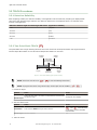
3.5.2 Two-Point Static TEACH
Two-point TEACH sets a single switching threshold. The sensor centers the switch point between two taught conditions
with the Output ON condition on one side and the Output OFF condition on the other.
2nd Taught
Condition
1st Taught
Condition
Sensor positions
threshold midway
between taught conditions
Output OFF
Darkest
(no signal)
Output ON
Position
adjusted by
Manual Adjust
Most Light
(saturated
signal)
Figure 8. Two-Point TEACH (Light Operate shown)
NOTE: The sensor must be set to
=
to use the following instructions.
NOTE: To program the sensor using remote input, remote input must be enabled (
=
)
1. Present the target.
Method
Action
Result
Push Button
Present the first target. The sensor-to-target distance must be within
the sensor's range.
The target's value displays.
Remote Input
2. Start the TEACH mode.
Method
Action
Result
Push Button
Press and hold TEACH for longer than 2 seconds.
and
flash alternately
on the display. The DYN and WND
indicators flash.
Remote Input
No action required.
n/a
3. Teach the sensor.
16
www.bannerengineering.com - Tel: 763.544.3164
Q3X Laser Contrast Sensor
Method
Action
Result
Push Button
Press TEACH to teach the target.
The sensor is taught the first target.
Remote Input
Single-pulse the remote input.
and
flash alternately
on the display. The DYN and WND
indicators flash.
T
4. Present the target.
Method
Push Button
Remote Input
Action
Result
Present the second target. The sensor-to-target distance must be
within the sensor's range.
and
flash alternately
on the display. The DYN and WND
indicators flash.
5. Teach the sensor.
Method
Action
Push Button
Press TEACH to teach the target.
Remote Input
Result
The sensor is taught the second
target and the sensor returns to Run
mode.
T
Single-pulse the remote input.
Table 3: Expected TEACH Behavior for Two-Point Static TEACH
Condition
TEACH Result
Display
At least one taught condition is
between the minimum and maximum
signal level limits.
Sets the threshold between the two
taught conditions.
The current NSS displays.
Both taught conditions are darker than
the minimum signal value limit.
Sets the threshold at the minimum
level. Sets the sensor at the maximum
detection condition.
briefly displays, and then the
current NSS displays.
Both taught conditions are brighter
than the maximum signal value limit.
Sets the threshold at the maximum
level. Sets the sensor at the minimum
detection condition.
briefly displays, and then the
current NSS displays.
Both taught conditions are at the same
signal level. This is a Calibration Set.
Sets the threshold slightly below the
two taught conditions.
briefly displays, and then the
current NSS displays.
3.5.3 Dynamic TEACH
Dynamic TEACH sets a single switching threshold during machine run conditions. Dynamic TEACH is recommended for
applications where a machine or process may not be stopped for teaching. During Dynamic TEACH, the sensor takes
multiple samples of the light and dark conditions and automatically sets the switch point at the optimum level.
Darkest Taught
Condition
Lightest Taught
Condition
Sensor positions
threshold midway
between taught conditions
Output OFF
Darkest
(no signal)
Output ON
Position
adjusted by
Manual Adjust
Most Light
(saturated
signal)
Figure 9. Dynamic TEACH (Light Operate shown)
www.bannerengineering.com - Tel: 763.544.3164
17
Q3X Laser Contrast Sensor
NOTE: The sensor must be set to
=
to use the following instructions.
NOTE: To program the sensor using remote input, remote input must be enabled (
=
)
1. Present the target.
Method
Action
Result
Push Button
Present the first target. The sensor-to-target distance must be within
the sensor's range.
The target's value displays.
Remote Input
2. Start the TEACH mode.
Method
Action
Result
Push Button
Press and hold TEACH for longer than 2 seconds.
and
flash alternately
on the display. The DYN indicator
flashes.
Remote Input
No action required.
n/a
3. Teach the sensor.
Method
Action
Result
Push Button
Press TEACH to teach the target.
The sensor begins sampling target
Remote Input
Single-pulse the remote input.
T
intensity information and
and
flash alternately on the
display. The DYN indicator flashes.
4. Present the targets.
Method
Action
Result
Push Button
Remote Input
Present additional targets. The sensor-to-target distance must be
within the sensor's range.
The sensor continues to sample
target intensity information and
and
flash alternately
on the display. The DYN indicator
flashes.
5. Teach the sensor.
Method
Action
Result
Push Button
Press TEACH to stop teaching the sensor.
Remote Input
Single-pulse the remote input.
T
The sensor sets the switching
threshold and returns to Run mode.
Table 4: Expected TEACH Behavior for Dynamic TEACH
Condition
TEACH Result
Display
At least one taught condition is
between the minimum and maximum
signal level limits.
Sets the threshold between the two
conditions.
The current NSS displays.
All conditions are darker than the
minimum signal value limit.
Sets the threshold at the minimum
level. Sets the sensor at the maximum
detection condition.
briefly displays, and then the
current NSS displays.
All conditions are brighter than the
maximum signal value limit.
Sets the threshold at the maximum
level. Sets the sensor at the minimum
detection condition.
briefly displays, and then the
current NSS displays.
18
www.bannerengineering.com - Tel: 763.544.3164
Q3X Laser Contrast Sensor
Condition
TEACH Result
Display
All conditions are at the same signal
level. This is a Calibration Set.
Sets the threshold slightly below the
two taught conditions.
briefly displays, and then the
current NSS displays.
3.5.4 Window Set
Window set sets a sensing window using the window offset percentage. Use the
percentage. The default is 20%.
menu to set the window offset
Sensing window size
adjusted by
Manual Adjust
Output OFF
Output ON
Darkest
(no signal)
Output OFF
Single
taught
point
Most Light
(saturated
signal)
Figure 10. Window Set (Light Operate shown)
NOTE: The sensor must be set to
=
to use the following instructions.
NOTE: To program the sensor using remote input, remote input must be enabled (
=
)
1. Present the target.
Method
Action
Result
Push Button
Present the target. The sensor-to-target distance must be within the
sensor's range.
The target's value displays.
Remote Input
2. Start the TEACH mode.
Method
Action
Result
Push Button
Press and hold TEACH for longer than 2 seconds.
and
flash alternately
on the display. The WND indicator
flashes.
Remote Input
No action required.
n/a
3. Teach the sensor.
Method
Action
Result
Push Button
Press TEACH to teach the target.
The sensor sets the window and
returns to Run mode.
Remote Input
Single-pulse the remote input.
T
flashes briefly on the display
and the sensor returns to Run mode.
Table 5: Expected TEACH Behavior for Window Set
Condition
TEACH Result
A valid condition is detected.
Sets a symmetric window around the
The current NSS displays.
taught condition. The threshold window
is set by the
Display
value.
www.bannerengineering.com - Tel: 763.544.3164
19
Q3X Laser Contrast Sensor
Condition
TEACH Result
Display
The taught condition is at a valid low
signal level.
Sets a symmetric window around the
taught condition, using the minimum
offset value.
The achieved percent briefly displays,
and then the current NSS displays.
The taught condition is less than the
minimum detection range.
Sets a single threshold at the minimum
briefly displays, and then the
level. Sets the sensor at the maximum
current NSS displays.
detection condition.
The taught condition plus the offset is
greater than the detection range.
Sets a single threshold at the
maximum level. Sets the sensor at the
minimum detection condition.
briefly displays, and then the
current NSS displays.
3.5.5 Light Set
Light set sets a switching threshold a user-selectable percent offset below the presented condition. Use the
set the offset percentage. The default is 20%.
menu to
Threshold position
adjusted by
Manual Adjust
Sensor positions the
threshold slightly below
the presented condition
Output OFF
Output ON
Condition
Presented
Darkest
(no signal)
Most Light
(saturated
signal)
Figure 11. Light Set (Light Operate shown)
NOTE: The sensor must be set to
=
to use the following instructions.
NOTE: To program the sensor using remote input, remote input must be enabled (
=
)
1. Present the target.
Method
Action
Result
Push Button
Present the target. The sensor-to-target distance must be within the
sensor's range.
The target's value displays.
Remote Input
2. Start the TEACH mode.
Method
Action
Result
Push Button
Press and hold TEACH for longer than 2 seconds.
and
flash alternately
on the display. The DYN and WND
indicators flash.
Remote Input
No action required.
n/a
3. Teach the sensor.
20
Method
Action
Result
Push Button
Press TEACH to teach the sensor.
The sensor sets the switching
threshold and returns to Run mode.
www.bannerengineering.com - Tel: 763.544.3164
Q3X Laser Contrast Sensor
Method
Action
Result
Remote Input
Single-pulse the remote input.
T
flashes briefly on the display
and the sensor returns to Run mode.
Table 6: Expected TEACH Behavior for Light Set
Condition
TEACH Result
Display
A valid condition is detected.
Sets the threshold at a value less than
the taught condition, as defined by the
The current NSS displays.
value.
The taught condition is at a low signal
level.
Sets the threshold at a percentage
greater than the value defined by the
value.
The taught condition is darker than the Sets the threshold at the minimum
minimum signal value limit.
level. Sets the sensor at the maximum
detection condition.
The taught condition is brighter than
the maximum signal value limit.
Sets the threshold at the maximum
level minus the
The percent offset needed with the
presented target briefly displays, then
the current NSS displays.
briefly displays, and then the
current NSS displays.
The current NSS displays.
value.
3.5.6 Dark Set
Dark set sets a switching threshold a user-selectable percent offset above the presented condition. Use the
set the offset percentage. The default is 50%.
menu to
Threshold position
adjusted by
Manual Adjust
Sensor positions
threshold slightly above
the presented condition
Output OFF
Darkest
(no signal)
Condition
Presented
Output ON
Most Light
(saturated
signal)
Figure 12. Dark Set (Light Operate shown)
NOTE: The sensor must be set to
=
to use the following instructions.
NOTE: To program the sensor using remote input, remote input must be enabled (
=
)
1. Present the target.
Method
Action
Result
Push Button
Present the target. The sensor-to-target distance must be within the
sensor's range.
The target's value displays.
Remote Input
2. Start the TEACH mode.
www.bannerengineering.com - Tel: 763.544.3164
21
Q3X Laser Contrast Sensor
Method
Action
Result
Push Button
Press and hold TEACH for longer than 2 seconds.
and
flash alternately
on the display. The DYN and WND
indicators flash.
Remote Input
No action required.
n/a
3. Teach the sensor.
Method
Action
Result
Push Button
Press TEACH to teach the sensor.
The sensor sets the switching
threshold and returns to Run mode.
Remote Input
Single-pulse the remote input.
T
flashes briefly on the display
and the sensor returns to Run mode.
Table 7: Expected TEACH Behavior for Dark Set
Condition
TEACH Result
Display
A valid condition is detected.
Sets the threshold at a value greater
than the taught condition, as defined
The current NSS displays.
by the
The taught condition is a low signal
level.
value.
Sets the threshold at a percentage
greater than the value defined by the
value.
The taught condition is darker than the Sets the threshold at the minimum
minimum signal value limit.
level. Sets the sensor at the maximum
detection condition.
The taught condition is brighter than
the maximum signal value limit.
Sets the threshold at the maximum
level. Sets the sensor at the minimum
detection condition.
The percent offset needed with the
presented target briefly displays, then
the current NSS displays.
briefly displays, and then the
current NSS displays.
briefly displays, and then the
current NSS displays.
3.6 Sync Master/Slave
Two Q3X sensors may be used together in a single sensing application. To eliminate crosstalk between the two sensors,
configure one sensor to be the master and one to be the slave. In this mode, the sensors alternate taking measurements
and the response speed is 25 ms.
1. Configure the first sensor as the master; navigate:
>
>
2. Configure the second sensor as the slave; navigate:
3. Connect the gray (input) wires of the two sensors together.
22
.
.
www.bannerengineering.com - Tel: 763.544.3164
Q3X Laser Contrast Sensor
3.7 Sensor Menu Map
Top Menu
Output Operation
Sub Menu
BOTH
sets
selection
BOTH
Light Operate
Dark Operate
Teach Process Selection
(
default setting)
BOTH
Two-Point Static Teach
Dynamic Teach
Window Set
Light Set
Dark Set
Offset Percentage
Response Speed
Output Timing Delays
BOTH
BOTH
BOTH
(min, 10, 20, 30, 40, 50) - Window & Light Set options (20% is default for Light Set and Window)
(min, 25, 50, 100, 200) - Dark Set options ( 50% is default for Dark Set)
Pct menu present when teach is set to Window, Light, or Dark
set Response Speed to 250 microseconds
set Response Speed to 1 millisecond
set Response Speed to 5 milliseconds
Response Speed menu not present when Input Wire Function set to Master or Slave
off: no delays enabled
on: enable on and/or off delay (set value in Delay Timer menu)
1 Shot, fixed output pulse duration
Delay Timer
Available when
set to “on”
ms to
Sensitivity
sec range, set Delay Timer value (seconds have decimal)
Menu not present when
is set to “off”
("ond" and "ofd" default to 0, “dt1” defaults to 1 or 10 depending on response speed setting)
Available when
set to “1Sh”
Input Wire Function
LO = Single fixed duration, On pulse when moving into light state
DO = Single fixed duration, On pulse when moving into dark state
BOTH
BOTH
BOTH
off: input is not active, ignore pulses
laser off when pulled low
laser on when pulled low
set: Remote Teach input
Master sync line for two sensor cross talk avoidance (response speed is 25 ms)
Slave sync line for two sensor cross talk avoidance (response speed is 25 ms)
standard sensitivity
high sensitivity
low sensitivity
Cut-off Output Operation
Display Read
BOTH
BOTH
Output follows LO/DO selection; sensor treats target in background as dark state
Output switches OFF when target is beyond background suppression distance
Output switches ON when target is beyond background suppression distance
CtO menu present on LD50 models only
display on
display on, inverted
display off (enters sleep mode after 60 seconds)
display off, inverted (enters sleep mode after 60 seconds)
Exit Setup
BOTH
end: exit setup
Reset to Factory Defaults
BOTH
no: do not reset to factory defaults
yes: reset to factory defaults
Figure 13. Setup Mode Menu Map
www.bannerengineering.com - Tel: 763.544.3164
23
Q3X Laser Contrast Sensor
4 Specifications
Sensing Range
Sensing Beam
Visible red Class 2 laser, 655 nm
Table 8: Sensing Range
Supply Voltage (Vcc)
10 to 30 V dc
Power and Current, exclusive of load
Supply Power: < 675 mW
Current consumption: < 28 mA at 24 V dc
Supply Protection Circuitry
Protected against reverse polarity and transient overvoltages
Repeatability
60 µs
Delay at Power Up
1s
Maximum Torque
Side mounting: 1 N·m (9 in·lbs)
Nose mounting: 10 N·m (88 in·lbs)
Model
Contrast Sensing
Range
Background
Suppression
Distance
Q3XTBLD-Q8
0 to 300 mm (11.81 in)
Not Applicable
Q3XTBLD50-Q8
0 to 50 mm (1.97 in)
60 mm (2.36 in)
Q3XTBLD100-Q8
0 to 100 mm (3.94 in)
120 mm (4.72 in)
Q3XTBLD150-Q8
0 to 150 mm (5.91 in)
190 mm (7.48 in)
Q3XTBLD200-Q8
0 to 200 mm (7.87 in)
280 mm (11.02 in)
Construction
Housing: Nickel-plated zinc die-cast
Side cover: Nickel-plated aluminum
Lens cover: Scratch-resistant PMMA acrylic
Lightpipes and display window: Polysulfone
Adjustment buttons: 316 stainless steel
Connector
5-pin M12 Euro-Style Integral Connector
Input Wire
Allowable Input Voltage Range: 0 to Vcc
Active Low (internal weak pullup—sinking current): Low State < 2.0
V at 1 mA max.
Beam Spot Size
Output Configuration
Bipolar (1 PNP & 1 NPN) output
Output Rating
Discrete Output: 100 mA maximum (protected against continuous
overload and short circuit)
Off-state Leakage Current: < 10 µA
NPN On-state saturation voltage: < 200 mV at 10 mA and < 1.0 V at
100 mA
PNP On-state saturation voltage: < 1 V at 10 mA and < 2.0 V at 100
mA
x
Table 9: Models LD, LD100, LD150, LD200
Ambient Light Immunity
> 5000 lux
Distance
20
mm
50
mm
100
mm
150
mm
200
mm
300
mm
X
5.9
mm
5.6
mm
5.1
mm
4.6
mm
4.1
mm
3.0
mm
Y
2.3
mm
2.1
mm
1.9
mm
1.6
mm
1.5
mm
1.2
mm
Response Speed
User selectable:
•
—250 microseconds
•
—1 millisecond
•
—5 milliseconds
Beam
Spot
Pattern
y
Table 10: Model LD50
Distance
Operating Conditions
Temperature: −10 °C to +50 °C (+14 °F to +122 °F)
Humidity: 35% to 95% relative humidity
Environmental Rating
IEC IP67 per IEC60529
IEC IP68 per IEC60529
IEC IP69K per DIN40050-9
20 mm
50 mm
X
4.8 mm
3.4 mm
Y
2.0 mm
1.4 mm
Vibration
MIL-STD-202G, Method 201A (10 to 60 Hz, 0.06 in (1.52 mm)
double amplitude, 2 hours each along X, Y and Z axes), with sensor
operating
Shock
MIL-STD-202G, Method 213B, Condition I (100G 6x along X, Y and
Z axes, 18 total shocks), with sensor operating
Storage Temperature
–25 °C to +75 °C (−13 °F to +167 °F)
24
www.bannerengineering.com - Tel: 763.544.3164
Q3X Laser Contrast Sensor
Required Overcurrent Protection
Certifications
WARNING: Electrical connections must be
made by qualified personnel in accordance with
local and national electrical codes and
regulations.
Industrial
Control
Equipment
3TJJ
Class 2 power
Overcurrent protection is required to be provided by end product
application per the supplied table.
Overcurrent protection may be provided with external fusing or via Current
Limiting, Class 2 Power Supply.
Supply wiring leads < 24 AWG shall not be spliced.
For additional product support, go to http://www.bannerengineering.com.
Supply Wiring
Required Overcurrent Protection
20
5.0 Amps
22
3.0 Amps
24
2.0 Amps
26
1.0 Amps
28
0.8 Amps
30
0.5 Amps
4.1 Performance Curves
Performance is based on a 90% reflectance white test card.
NOTE: For high sensitivity, the excess gain increases by a factor of 1.5. For low sensitivity, the excess
gain decreases by a factor of 0.75
Q3XTBLD Models
Q3XTBLD50 Models
EXCESS GAIN
100
10
1
1000
EXCESS GAIN
1000
1000
EXCESS GAIN
Q3XTBLD100 Models
100
10
1
1
10
100
DISTANCE (mm)
Figure 14. Excess Gain for Standard
Sensitivity
1000
100
10
1
1
10
100
1
10
100
1000
DISTANCE (mm)
DISTANCE (mm)
Figure 15. Excess Gain for Standard
Sensitivity
Figure 16. Excess Gain for Standard
Sensitivity
For LD50 and LD100 models, the sensing cut-off distance of a 6% reflective
black card will be 95% of the sensing cut-off distance of a 90% reflective white
card.
www.bannerengineering.com - Tel: 763.544.3164
25
Q3X Laser Contrast Sensor
Q3XTBLD150 Models
Q3XTBLD200 Models
1000
EXCESS GAIN
EXCESS GAIN
1000
100
10
1
100
10
1
1
10
100
1000
1
10
100
1000
DISTANCE (mm)
DISTANCE (mm)
Figure 17. Excess Gain for Standard Sensitivity
Figure 18. Excess Gain for Standard Sensitivity
For 150 mm models, the sensing cut-off distance for a 6%
reflective black card will be 65% of the sensing cut-off
distance of a 90% reflective white card.
For 200 mm models, the sensing cut-off distance for a 6%
reflective black card will be 50% of the sensing cut-off
distance of a 90% reflective white card.
4.2 Dimensions
All measurements are listed in millimeters (inches), unless noted otherwise.
35.26
Ø3.30
RECEIVER
1.21
24.30
1.50
12.05
24.10
3.50
M18 X 1-6g
34.80
47.10
EMITTER
18.05
1.30
3.80
18.00
3.30
26
www.bannerengineering.com - Tel: 763.544.3164
14.90
M12 X 1-6g
Q3X Laser Contrast Sensor
5 Abbreviations
The following table describes the abbreviations used on the sensor display.
Abbreviation
Description
No light received (loss of signal)
The signal is saturated
One shot
First
One point
Second
Two-point static TEACH
Bottom—The sensor is at minimum gain during a manual adjustment or after a TEACH
Calibration set
Cutoff—A target is detected in the background (models with background suppression only)
Output timing delays
Dark operate
Dark set
Display read
Delay timer
Dynamic TEACH
Excess gain
Exit to Run mode
Go
High sensitivity
Input wire function
Light operate or low sensitivity
Lock
Laser off
Light set
Minimum
Master
Off delay
On delay
www.bannerengineering.com - Tel: 763.544.3164
27
Q3X Laser Contrast Sensor
Abbreviation
Description
Output operation
Offset percentage
Reset to factory defaults
Sensitivity
Input wire = remote teach function
or
Set (used in the TEACH procedures)
Standard sensitivity
Slave
Response speed
Stop
Teach process selection
Top—The sensor is at maximum gain during a manual adjust or after a TEACH
Window set
Unlock
28
www.bannerengineering.com - Tel: 763.544.3164
Q3X Laser Contrast Sensor
6 Troubleshooting
Table 11: Troubleshooting Codes
Code
Description
Resolution
No light received
For some applications, reposition the
sensor or the target
The signal is saturated
For some applications, reposition the
sensor or the target
Description
Resolution
Output short circuit
Check the wiring for an electrical short
circuit
Laser fault
Contact Banner Engineering to resolve
EEPROM or System Fault
Contact Banner Engineering to resolve
Table 12: Error Codes
Code
The display is blank and the output
indicator flashes
www.bannerengineering.com - Tel: 763.544.3164
29
Q3X Laser Contrast Sensor
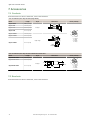
7 Accessories
7.1 Cordsets
All measurements are listed in millimeters, unless noted otherwise.
5-Pin Threaded M12/Euro-Style Cordsets (Single Ended)
Model
MQDC1-501.5
Length
1.83 m (6 ft)
MQDC1-515
4.57 m (15 ft)
MQDC1-530
9.14 m (30 ft)
MQDC1-515RA
Dimensions
0.50 m (1.5 ft)
MQDC1-506
MQDC1-506RA
Style
44 Typ.
Straight
M12 x 1
ø 14.5
2
1
3
1.83 m (6 ft)
4
32 Typ.
[1.26"]
4.57 m (15 ft)
5
1 = Brown
2 = White
3 = Blue
4 = Black
5 = Gray
30 Typ.
[1.18"]
Right-Angle
MQDC1-530RA
Pinout (Female)
9.14 m (30 ft)
M12 x 1
ø 14.5 [0.57"]
5-Pin Threaded M12/Euro-Style Cordsets—Washdown Stainless Steel
Model
Length
MQDC-WDSS-0506
1.83 m (6 ft)
MQDC-WDSS-0515
4.57 m (15 ft)
Style
Dimensions
Pinout (Female)
2
1
3
Straight
MQDC-WDSS-0530
4
Ø15.5 mm
Ø4.8 mm
9.14 m (30 ft)
43.5 mm
7.2 Brackets
All measurements are listed in millimeters, unless noted otherwise.
30
www.bannerengineering.com - Tel: 763.544.3164
5
1 = Brown
2 = White
3 = Blue
4 = Black
5 = Gray
Q3X Laser Contrast Sensor
SMBQ4X..
•
Swivel bracket with tilt
and pan movement for
precision adjustment
•
Easy sensor mounting to
extruded rail T-slots
•
Metric and inch size bolts
available
•
Side mounting of some
sensors with the 3 mm
screws included with the
sensor
40
43
B
A
SMB18FA..
•
Swivel bracket with tilt and
pan movement for precision
adjustment
•
Easy sensor mounting to
extruded rail T-slots
•
Metric and inch size bolts
available
•
18 mm sensor mounting
hole
66
B
69
A
Hole size: B=ø 18.1
B = 7 × M3 × 0.5
Model
Bolt Thread (A)
Model
Bolt Thread (A)
SMB18FA
3/8 - 16 × 2 in
SMBQ4XFA
3/8 - 16 × 2¼ in
SMB18FAM10
M10 - 1.5 × 50
SMBQ4XFAM10
M10 - 1.5 × 50
SMB18FAM12
SMBQ4XFAM12
n/a; no bolt included. Mounts
directly to 12 mm (½ in) rods
n/a; no bolt included. Mounts
directly to 12 mm (½ in) rods
SMB18A
Right-angle mounting
•
bracket with a curved
slot for versatile
orientation
•
12-ga. stainless steel
•
18 mm sensor mounting
hole
•
Clearance for M4 (#8)
hardware
30
C
A
41
B
46
Hole center spacing: A to B = 24.2
Hole size: A = ø 4.6, B = 17.0 × 4.6, C = ø 18.5
www.bannerengineering.com - Tel: 763.544.3164
31
Q3X Laser Contrast Sensor
8 Contact Us
Corporate Headquarters
Phone: +1 763 544 3164
Website: www.bannerengineering.com
Address:
Banner Engineering Corporate
9714 Tenth Avenue North
Minneapolis, Minnesota 55441, USA
Europe
Phone: +32 (0)2 456 0780
Website: www.bannerengineering.com/eu
Email: [email protected]
Address:
Banner Engineering EMEA
Park Lane Culliganlaan 2F
Diegem B-1831, Belgium
Turkey
Phone: +90 216 688 8282
Website: www.bannerengineering.com.tr
Email: [email protected]
Address:
Banner Engineering Turkey
Barbaros Mah. Uphill Court Towers A Blok D:49
34746 Batı Ataşehir Istanbul Türkiye
India
Address:
Banner Engineering India Pune Head Quarters
Office No. 1001, 10th Floor Sai Capital, Opp. ICC Senapati Bapat Road
Pune 411016, India
Phone: +91 (0) 206 640 5624
Website: www.bannerengineering.co.in
Email: [email protected]
Mexico
Address:
Banner Engineering de Mexico Monterrey Head Office
Edificio VAO Av. David Alfaro Siqueiros No.103 Col. Valle Oriente C.P.66269
San Pedro Garza Garcia, Nuevo Leon, Mexico
Phone: +52 81 8363 2714 or 01 800 BANNERE (toll free)
Website: www.bannerengineering.com.mx
Email: [email protected]
Brazil
Address:
Banner do Brasil
Rua Barão de Teffé nº 1000, sala 54
Campos Elíseos, Jundiaí - SP, CEP.: 13208-761, Brasil
Phone: +1 763 544 3164
Website: www.bannerengineering.com.br
Email: [email protected]
China
Address:
Banner Engineering Shanghai Rep Office
Xinlian Scientific Research Building Level 12, Building 2
1535 Hongmei Road, Shanghai 200233, China
Phone: +86 212 422 6888
Website: www.bannerengineering.com.cn
Email: [email protected]
Japan
Address:
Banner Engineering Japan
Cent-Urban Building 305 3-23-15 Nishi-Nakajima Yodogawa-Ku
Osaka 532-0011, Japan
Phone: +81 (0)6 6309 0411
Website: www.bannerengineering.co.jp
Email: [email protected]
Taiwan
Address:
Banner Engineering Taiwan
8F-2, No. 308 Section 1, Neihu Road
Taipei 114, Taiwan
32
Phone: +886 (0)2 8751 9966
Website: www.bannerengineering.com.tw
Email: [email protected]
www.bannerengineering.com - Tel: 763.544.3164
Q3X Laser Contrast Sensor
9 Banner Engineering Corp Limited Warranty
Banner Engineering Corp. warrants its products to be free from defects in material and workmanship for one year following
the date of shipment. Banner Engineering Corp. will repair or replace, free of charge, any product of its manufacture
which, at the time it is returned to the factory, is found to have been defective during the warranty period. This warranty
does not cover damage or liability for misuse, abuse, or the improper application or installation of the Banner product.
THIS LIMITED WARRANTY IS EXCLUSIVE AND IN LIEU OF ALL OTHER WARRANTIES WHETHER EXPRESS OR
IMPLIED (INCLUDING, WITHOUT LIMITATION, ANY WARRANTY OF MERCHANTABILITY OR FITNESS FOR A
PARTICULAR PURPOSE), AND WHETHER ARISING UNDER COURSE OF PERFORMANCE, COURSE OF DEALING OR
TRADE USAGE.
This Warranty is exclusive and limited to repair or, at the discretion of Banner Engineering Corp., replacement. IN NO
EVENT SHALL BANNER ENGINEERING CORP. BE LIABLE TO BUYER OR ANY OTHER PERSON OR ENTITY FOR
ANY EXTRA COSTS, EXPENSES, LOSSES, LOSS OF PROFITS, OR ANY INCIDENTAL, CONSEQUENTIAL OR
SPECIAL DAMAGES RESULTING FROM ANY PRODUCT DEFECT OR FROM THE USE OR INABILITY TO USE THE
PRODUCT, WHETHER ARISING IN CONTRACT OR WARRANTY, STATUTE, TORT, STRICT LIABILITY,
NEGLIGENCE, OR OTHERWISE.
Banner Engineering Corp. reserves the right to change, modify or improve the design of the product without assuming any
obligations or liabilities relating to any product previously manufactured by Banner Engineering Corp.
www.bannerengineering.com - Tel: 763.544.3164
33


![iVu Plus BCR Gen2 Instruction Manual (Online Only) [ 179047 ]](http://vs1.manualzilla.com/store/data/005859145_1-6c6bbc2cdc90a8f85e92b64ee4999fc2-150x150.png)