1
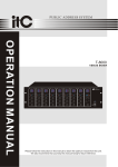
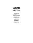
USER' S MANUAL
PROFESSIONAL SOUND MIXER
MX24.4/32.4
GUARANTEE
Topp Pro guarantees the normal operation of the product against any defect of manufacture
and/or vice of material, by the term of (12) months, counted as of the date of purchase on
the part of the user, committing itself to repair or to change, to its election, without position
some, any piece or component that will fail in normal conditions of use within the mentioned
period.
This guarantee is valid if the original buyer will have to present /display this certificate
properly sealed and signed by the selling house, accompanied by the corresponding invoice
of purchase where it consisted the model and serial number of the acquired equipment.
The guarantee does not cover:
- Damages caused by the illegal use of the product, repair and / or nonauthorized modification
conducted by people by Topp Pro.
- Damages caused by the connection of the equipment to other equipment different from
the specified ones in the manual of use, or by bad connection to these last ones.
- Damages caused by electrical storms, blows and / or incorrect transport.
- Damages caused by excesses or falls of tension in the network or by connection to
networks with a tension different from the required one by the unit.
- Damages caused by the presence of sand, acid of batteries, water, or any strange
element inside the equipment.
- Deteriorations produced by the course of the time, use and/or normal wear of the unit.
- Alteraion or absence of the serial number of factory of the equipment.
The repairs could only be carried out the authorized technical service by Topp Pro, that will
inform about the term and other details into the repairs to take place according to this guarantee.
Topp pro, will repair this unit in counted a term nongreater to 30 days as of the date
of entrance of the unit to the Technical Service. In those cases in that due to the
particularity of the spare part, outside necessary their import, the repair time and the
viability of the same one will be subject to the effective norms for the import of parts,
in which case one will inquire to the user about the term and possibility into repair.
With the object of its correct operation, and of the validity of this one guarantee, this
product will have to be installed and to be used according to the instructions that are
detailed in the manual associate or the package of the product.
This unit will be able to appear for its repair, next to the invoice of purchase (or any other
comprobante where the date of purchase consists), to its authorized distributer Topp Pro or
an authorized technical center on watch by Topp Pro.
9
Exclusion of damages:
THE RESPONSIBILITY OF TOPP PRO BY ANY DEFECTIVE PRODUCT IS LIMITED THE REPAIR OR THE
REPLACEMENT OF HE HIMSELF, TO TOPP OPTION PRO. IF WE CHOSE TO REPLACE THE PRODUCT,
THE REPLACEMENT CAN BE A RECONDITIONATED UNIT. TOPP PRO WILL NOT BE RESPONSIBLE
BY THE DAMAGES BASED ON THE LOST, INCONVENIENCE, LOSS OF USE, BENEFITS, LOST
SAVINGS, BY THE DAMAGE TO OTHER EQUIPMENT OR OTHER ARTICLES IN THE USE SITE,
OR BY ANY OTHER DAMAGE IF HE IS FORTUITOUS, CONSEQUENT OR OF ANOTHER TYPE,
ALTHOUGH TOPP PRO HAS BEEN NOTICED OF THE POSSIBILITY OF SUCH DAMAGES.
Some states do not allow to exclusion or the limitation to the fortuitous or consequent
damages, so the aforesaid limitation can not be applied to you.
This guarantee gives specific legal rights him, you can also have other right that varies of
state to state.
8
TECHNICAL SPECIFICATION
TABLE OF CONTENTS
Input
Input impedance
Mic 2 kohm Balanced
Line 10kohm Balanced
Input gain
Mic continuously variable from 0dB to +50dB
Line-Mono Channel continuously variable from
-15dBto+35dB
1. INTRODUCTION.........................................................................................1
2. FEATURES..................................................................................................1
3. USEFUL DATA............................................................................................1
4. CONTROL ELEMENTS................................................................................3
Maximum input level
Mic +22dBu
Line(Mono Channel)+22dBu
Line(Stereo Channel)+22dBu
Insert send impedance
120 ohm Unbalanced
Insert send level/Max
-10dBu/+22dBu
Insert return impedance
10 kohm Unbalanced
Insert return level/Max.
-10dBu/+22dBu
CMR at 1 kHz Line(20Hz-20kHz)
>60dB
Frequency Response
Mic to Mix 20Hz-20kHz +/-3dB
Signal/Noise Ratio(20Hz-20kHz)
Mic EIN ref.150ohms - 117dBu
System Noise(20Hz-20kHz)
Summing noise
-90dBu(24channels routed with faders down)
Line to Mix Noise
-86dBu(24 channels routed at 0dB, pan center)
Distortion at 1 kHz
Mic to insert(+30dB unity gain, +20dBu output(<0.009%
Mix to Mix(+30dB unity gain, +20dBu output)Typ 0.03%
Crosstalk at 1 kHz
Channel to channel >-80dB
Mix to Mix >-80dB
Channel to Mix >-80dB
Fader Attenuation
>100dB
Output impedance
All line outputs 120 ohm Balanced
Insert send impedance
120 ohm Unbalanced
Insert send level/max
+22dBu
Insert return impedance
10 kohm Unbalanced
Insert return level/max
+22dBu
Maximum output level master
outputs on XLR
+28dBu
All outputs on 1/4" jacks
Headphones
+22dBu/600 ohm
Main Mix Section
HI-shelving
+/-15dB @12 kHz
MID HI-bell(STEREO)
+/-12dB @3 kHz
MID-bell(MONO)
+/-12dB frequency range 100Hz - 8KHz
MID LOW-bell(STEREO)
+/-12dB @ 500hz
Bass-shelving
+/-15dB @ 80Hz
Hi Pass Filter Slope
-18dB/Oct. @75Hz
Power Supply
USA/Canada
Europe
U.K./Australia
'
100-120VAC~60Hz
210-240VAC~50Hz
240VAC~50Hz
5. OPTIONAL MODULES ..............................................................................9
6. INSTALLATION AND CONNECTIONS........................................................16
7. BLOCK DIAGRAM ...................................................................................18
8. TECHNICAL SPECIFICATION.....................................................................19
9. GUARANTEE ...........................................................................................20
INTRODUCTION
BLOCK DIAGRAM
FEATURES
* 18/26 MIC inputs with gold plated XLR and balanced LINE inputs
* 6 Stereo input channels with balanced TRS jacks
* Ultra-low noise discrete MIC preamps with +48 V Phantom Power
* Extremely high headroom offering more dynamic range
*Each input channel with Mute, SOLO function, overload LEDs & low cut filters
* MIC channel with LOW CUT filters and PHASE
* 6 AUX sends per channel, AUX1-2/AUX3-4/AUX5-6 with PRE/POST faders switchable
* 4-band EQ with two swept mid on microphone channels
* 4-band fixed EQ on stereo channels
* SUB1-2,SUB3-4,MAIN L-R, CENTER signal assignment switch
* 100mm high precision faders
* Channel inserts and direct outputs on each mono channel plus main mix insert for flexible
connection of outboard equipment
* MATRIX A & B for (SUB1-SUB2)(SUB3-SUB4)(L-R)(CENTER)
* Control room/phones matrix
* 2-TRACK IN assignable to main mix, control room/headphone outputs
* Fully assignable Talkback sections
* With USB port, record from SUB1-2 or MAIN OUT and play to CH23-24 or MAIN BUS
* Option DSP effect with 100effects
* Option Stereo 9-band graphic EQ for MAIN
* Option 4 MP3 PLAYER modules
USEFUL DATA
Please write your serial number here for future reference.
Serial Number:
Data of Purchase:
Purchased at:
&
%
Y-Stereo lead for insert Connection
(To be used when the processor does not employ a
single jack connection for the In/Out Connections)
To Processor Output
Apparaten skall anslutas
till jordat uttag nar den
ansluts till ett natverk
100-240V~50/60Hz
FUSE: T1.6AL
RATED POWER CONSUMPTION: 80W
AC INPUT
Use only with a 250V fuse
Ring=Return Signal
OFF
To Channel Insert
POWER
Tip=Send Signal
ON
1
Tip
R
R
L
R
L
4
SUBGROUPS INSERT
3
2
6
R
4
5
R
SUBGROUPS OUT
3
2
AUX SENDS
4
MAIN MIX OUTPUT
1
B
L
1
MATRIX
A
3
ACTIVE SPEAKERS
CENTER
2
R
To Processor Input
R
INSERT
PHANTOM
3
1
IN
OUT
2-TRACK
RIGHT
RIGHT
LINE IN 22
LEFT
(MONO)
BAL/UNBAL
CD PLAYER
R
1
LEFT
(MONO)
LINE IN 24
L
3
LINE IN 21
2
MIC17
BAL/UNBAL
LINE IN 23
2
ON
'Tapped' Connection Direct Output Lead
(Enables the Insert to be used as a Direct Output
while maintaining the channel signal flow)
MIC18
3
1
3
1
LEFT
(MONO)
BAL/UNBAL
MAIN
MIX.
MAIN
MIX.
2
3
1
MIC14
RIGHT
LINE IN 16
BAL/UNBAL
LEFT
(MONO)
LINE IN 15
COMPUTER
PLAY BACK
CH
23/24
RIGHT
LINE IN 18
RECORD
SUB
1/2
2
MIC15
LINE IN 17
USB
RIGHT
LINE IN 20
BAL/UNBAL
LEFT
(MONO)
LINE IN 19
2
MIC16
To Tape or FX Input
R
OFF
Sleeve=Ground/Screen
4
Tip=Signal
L
3
1
RIGHT
LINE IN 14
BAL/UNBAL
LEFT
(MONO)
LINE IN 13
2
MIC13
Sleeve=Ground/Screen
L
To Channel Insert
L
PHANTOM
2
3
1
MIC12
ON
DIRECT OUT
INSERT
BAL/UNBAL
LINE IN 12
OFF
Ring=Return Signal (Connected together)
L
3
1
3
1
DIRECT OUT
INSERT
BAL/UNBAL
LINE IN 10
2
MIC10
2
3
1
DIRECT OUT
INSERT
BAL/UNBAL
LINE IN 9
KEYBOARD
DIRECT OUT
INSERT
BAL/UNBAL
LINE IN 11
2
MIC11
MIC9
(seen from soldering side)
L
3-pin XLR Line Socket
AUX RETURNS
3
3-pin XLR Male Plug
(seen from soldering side)
2
2
3
1
MIC8
PHANTOM
ON
DIRECT OUT
INSERT
BAL/UNBAL
LINE IN 8
OFF
3=Cold(-)
Use for Main output
(For unbalanced use, leave pin3 unconnected)
1
3=Cold(-)
Use for Balanced Mic Inputs
(For unbalanced use, connect pin 1 to 3)
CTRL OUT
1=Ground/Screen
PHONE
1
3
Ring
3
1
Sleeve=Ground/Screen
2
2
Sleeve
2=Hot(+)
TALK BACK
1=Ground/Screen
ACTIVE SPEAKERS
USB Connection
1
DRUM MACHINE
3
CD PLAYER
2
STAGE MONITOR
1/4" Stereo (TRS) Jack Plug
BASS
3
1
DIRECT OUT
INSERT
BAL/UNBAL
LINE IN 7
2
MIC7
3
1
DIRECT OUT
INSERT
BAL/UNBAL
LINE IN 6
2
MIC6
3
1
SERIAL
MODEL
DIRECT OUT
INSERT
BAL/UNBAL
LINE IN 5
2
MIC5
2
3
1
MIC4
PHANTOM
ON
DIRECT OUT
INSERT
BAL/UNBAL
LINE IN 4
OFF
Use for Insert Points
1
1
DIRECT OUT
INSERT
BAL/UNBAL
LINE IN 2
3
MIC2
2
DESIGNED IN ITALY
DIRECT OUT
INSERT
BAL/UNBAL
LINE IN 3
3
MIC3
2
3
1
DIRECT OUT
INSERT
BAL/UNBAL
LINE IN 1
2
MIC1
MIC 1
Tip=Send Signal
GUITAR
Sleeve=Ground/Screen
MIC 2
Strain Clamp
HEADPHONE
D/I BOX
2=Hot(+)
Tip
Ring
MIC 3
Sleeve
WIRELESS
WIRELESS
MICROPHONE 2MICROPHONE 1 MIC 4
INSTALLATION AND CONNECTIONS
HOOKUP DIAGRAM
Ring=Return Signal
INSTALLATION AND CONNECTIONS
CONTROL ELEMENTS
FRONT PANEL
1- PHASE SWITCH(EXCEPT FOR CH21/22, 23/24)
1
PHASE
75Hz
18dB / Oct
LOW CUT
TRIM
2- LOW-CUT BUTTON
LEVEL
SET
OdB 50dB MIC
+15dB -35dB LINE
5
3- TRIM
21/22
23/24
LINE
MP3
HI
12kHz
7
8
4-
HI
12kHz
MID-H
3.0
0.5
MID-H
freq
KHz
MID-H
3kHz
9
12
MID-L
MID-L
500Hz
LEVEL SET LED
450
80
MID-L
freq
Hz
2K
11
LOW
80Hz
LOW
60Hz
OFF
ON
OFF
ON
EQ
1
5-
EQ
AUX
1
You can connect unbalanced equipment to balanced inputs and outputs. Simply follow these schematics.
AUX
2
POST
PRE
POST
PRE
3
3
4
4
LINE/USB BUTTON(CH 23/24)
DFX1
5
DFX1
6
DFX2
6
DFX2
Ring=Right Signal
Tip=Left Signal
Strain Clamp
Sleeve=Ground/Screen
Use for Headphone
PEAK
dB
MUTE
SUB 1-2
dB
16
SUB 1 2
5
SUB 3-4
0
5
MUTE
PEAK
10
5
SUB 3 4
0
MAIN L-R
Sleeve
MAIN L R
Tip
5
CENTER
17
1/4" Stereo (TRS) Jack Plug
POST
PRE
BAL
14
15
10
7- HIGH
Tip
Ring
POST
PRE
5
POST
PRE
EQUALISER
Sleeve
13
POST
PRE
CENTER
Tip=Signal
Strain Clamp
10
10
15
15
20
20
30
30
60
60
SOLO
12
!
10
12
LINE/MP3 BUTTON(CH 21/22)
2
6-
6
LINE
USB
18
Sleeve=Ground/Screen
Use for Mono Line In, Mono 1/4"Jack Plugs
SOLO
1/4" Mono (TS) Jack Plug
13/14
$
CONTROL ELEMENTS
OPTIONAL MODULES
8- MID-HI(0.5-12K) & MID-LOW(80-2K)
9- HI-MID
10- MID-LOW
11- LOW
9- DISPLAY
All the USB player information are monitored through this sexy & magic display.
12- EQ SWITCH
USB Module Installation
-No selective mode
At normal state, there is no selective mode on the front panel, only a piece of panel without function.
13-AUX SENDS LEVEL CONTROL
CN16
CN17 CN33
Mp3 MOD
-USB PLAYER selective mode
Please connect the 5PIN row-wire on the USB module to the CN16 header and 2 PIN row-wire to
CN 33header on front panel. For Recording module, you also need to connect the 3 PIN row-wire
to CN 17header to start recording function. Then fix the USB module on front panel with two screws.
14-PAN/BAL CONTROL
15-PEAK LED
USB PLAYER
CN16
CN17 CN33
Mp3 MOD
TAC-MP3-S
16-MUTE BUTTON & LED
USB PLAYER
CN16
TAC-MP3-T
POWER
(Push & Hold)
Mp3 MOD
CN16
USB PLAYER-RECORDER
CN17 CN33
CN17 CN33
17-FADER
18-ASSIGNMENT Controls
VOL+ VOL-
TAC-MP3-R
#
REC
RPT POWER
(Push & Hold)
Mp3 MOD
"
OPTIONAL MODULES
CONTROL ELEMENTS
5PLAY/PAUSE
In play state, press
key to start playing.
PLAY/PAUSE key to pause the player. In pause state, press
PLAY/PAUSE
6- STOP
In play state, press this key to stop playing and all the songs in USB memory will appear on the display;
In stop state, press STOP/
PRE/
NEXT keys again to go to first song and the player will keep in
pause state, then press
PLAY/PAUSE key to play the song.
19-
MASTER AUX SENDS CONTROLS
8- DISPLAY:
All MP3 player information are monitored via this sexy & magic display.
20-
SOLO Button
21-
MASTER STEREO AUX RETURNS CONTROLS
22-
TO AUX SEND1/2
Option Three - Recording Module
23-
The file system of USB memory for USB players is FAT16 and FAT32, and these players can only
decode MP3. It has 7 rank subordinate folders at most.
SUB1-2/SUB3-4/MAIN L-R/CENTER BUTTONS
(9)
AUX SENDS
STEREO AUX RETURNS
1
1
1
2
2
MATRIXS
A
CLIP
TO AUX
SEND1
13
SOLO
MAX
MAX
10
7
SUB 2
2
(2) (1) (3)(4)
PWR
B
SUB 1
4
TO AUX
SEND2
USB PLAYER-RECORDER
2
MAX
SOLO
0
MAX
-2
SUB 3
-4
3
3
-7
SUB1-2
SUB3-4
MAIN L-R
CENTER
MAX
-13
SUB 4
3-DFX1 RETURN
VOL+ VOL-
-10
MAX
SOLO
-16
-20
4
4
MAX
SUB1-2
SUB3-4
MAIN L-R
CENTER
24-
MATRIX A&B
TAC-MP3-R
-30
L
4-DFX2 RETURN
R
OUTPUT LEVEL
MAX
5
-25
MAX
MAIN L
SOLO
DFX1 SEND
SOLO
2-TRACK IN
MAX
MAX
CENTER
DFX2 SEND
SOLO MODE
PFL
AFL
PAN
-
8
C.ROOM/
PHONES
SOLO
+10
PAN
MAIN L-R
CTRL ROOM
PAN
MAX
PAN
RPT POWER
(Push & Hold)
SOLO ACTIVE AFL
MAIN R
6
REC
MAX
(5)(6)(7)
(8)
MAX
MASTER
CTRL ROOM SOURCES
LEFT
RIGHT
MAIN L-R
25-
2TK LEVEL & TO MIX BUTTON
MAIN L-R
LEFT
RIGHT
MAIN L-R
LEFT
0
0
MATRIX A
MATRIX B
RIGHT
MAIN L-R
SUB 1-2
SUB 3-4
MAIN L-R
CENTER
10
10
10
10
10
10
dB
dB
dB
dB
dB
dB
dB
5
5
5
5
5
5
5
0
0
0
0
0
0
0
-5
-5
-5
-5
-5
-5
-5
-10
-10
-10
-10
-10
-10
-10
-20
-20
-20
-20
-20
-20
-20
-30
-30
-30
-30
-30
-30
-30
-40
-40
-40
-40
-40
-40
-40
-50
-50
-50
-50
-50
-50
-50
-60
-60
-60
#
RIGHT
10
SUB1
26-
LEFT
-60
SUB2
SUB3
SUB4
-60
MAIN L
-60
MAIN R
-60
CENTER
SUBGROUPS ASSIGN TO MAIN MIX
"
OPTIONAL MODULES
CONTROL ELEMENTS
[ 002 ] 00 : 05
27-
POWER LED
28-
LED METER
29-
SOLO ACTIVE/AFL
30-
SOLO MODE BUTTON
31-
PHONES/CTRL ROOM CONTROL
01. Plena pop 01.mp
02. Pop 02.mp3
03. Plena pop 03.mp
.EC "
PLAYLIST SET
PLAYING LIST
.EC #
c) The display will show the following interface. Press the
PRE /
NEXT key, you can select the starting song, then press
the
PLAY/PAUSE key, the selected song playback will start.
Press
PLAY/PAUSE key again, or press STOP key, the play
back will stop. Press
PLAY/PAUSE key again, or press STOP
key, the playback will start again from the same point. Twice
press STOP, the USB player will return to Fig 3 interface.
5-Folder List:
See the Fig 3, the display shows MP3 files folders names. Use
PRE/
NEXT key to scan, press
PLAY/PAUSE key, you'll
enter into corresponding folder. In order to return to Fig5
interface, you just need to press the STOP key.
classic music
[ . ] p3
Plena pop
[ ]Plena pop 02.mp
[ . ]Plena pop 03.mp
.EC $
[ . ] 00 : 20
01. lena pop 02.mp3
32- CONTROL ROOM SOURCE
02. Plena pop 06.mp
03. Plena pop 04.mp
.EC %
33- SUBGROUPS FADER
Option Two - Track Module
The file system of USB memory for USB players is FAT16 and FAT32, and these players can only
decode Mp3. It has 7 rank subordinate folders at most.
2-
PRE
(8)
NEXT
TALK BACK
(2) (1) (3) (4)
35- TALKBACK LEVEL
USB PLAYER
3-
34- MAIN MIX LEVEL FADER
TAC-MP3-T
POWER
(Push & Hold)
(5)(6)
(7)
36- TALKBACK SWITCH
This switch activates and sends the talkback signal to its selected
outputs.
ON
SUB1-2
SUB3-4
MAIN L-R
CENTER
AUX1-2
AUX3-4
AUX5-6
37- TALKBACK SIGNAL ASSIGNMENT SWITCHES
4- RPT
Press this key, the player will change between the following four modes:
REP ALL means to repeat all tracks in the memory, mark on the screen is
REP1 means to repeat one track, the mark on the screen is
Play in order means to play the tracks according to the order, the mark on the screen is blank.
Random play means to play the tracks at random, the mark on the screen is A.
!
$
OPTIONAL MODULES
CONTROL ELEMENTS
Optional USB Players Modules Section
This section can be selected and installed according to user's requirement. Please see installation
procedure .(USB Module Installation)
PHANTOM
OFF
ON
MIC4
2
Option One - Song Module
1
3
The file system of USB memory for USB players is FAT16 and FAT32, and these players can only
decode Mp3. It has 7 rank subordinate folders at most.
LINE IN 4
BAL/UNBAL
INSERT
DIRECT OUT
PHANTOM
OFF
ON
MIC18
2
1
(6)
3
(4) (2) (1)
(3) (5)
LINE IN 23
LEFT
(MONO)
USB PLAYER
BAL/UNBAL
LINE IN 24
RIGHT
TAC-MP3-S
INSERT USB KEY
Fig 1
MENU:
PLAYING
PROGRAM
FOLDER LIST
Fig 2
2-TRACK
L
FOLDER:
R
IN
classic music
OUT
jazz music
pop music
USB
SUB
1/2
MAIN
MIX.
RECORD
%
.EC !
CH
23/24
MAIN
MIX.
PLAY BACK
CONTROL ELEMENTS
OPTIONAL MODULES
function
1- DISPLAY
It displays the selected preset.
2- PRESETS SELECTOR
TALK BACK
PHONE
1
2
1
3
3- DSP MUTE Switch & PEAK LED
1
AUX RETURNS
3
CTRL OUT
2
4
L
L
L
L
L
R
R
R
R
R
2
3
5
6
MATRIX
A
1
2
B
1
SUBGROUPS INSERT
3
2
AUX SENDS
4
POWER
CENTER
ON
OFF
SUBGROUPS OUT
3
4
4
INSERT
MAIN MIX OUTPUT
Preset list for DSP effect
Use only with a 250V fuse
NO.
Preset
Description
Parameter
00~09
Echo
Reproduce the sound in input on the
output after a lapse of time or delay.
Delay Time : 145~205ms
10~19
Echo+Verb
Echo with Room effect.
Delay Time : 208~650ms
Decay time : 1.7~2.1s
20~29
Tremolo
Amplitude modulation of the signal.
Rate : 0.6 Hz~5 Hz
30~39
Plate
Simulate the transducers sound like
classic bright vocal plate.
Decay time:0.9s~3.6s
40~49
Leslie
Recreate the illusion of more than one
instrument from a single instrument sound.
Rate : 0.92Hz ~1.72Hz
50~59
Vocal
Simulate a small space with slight
decay time.
Rev. decay time: 0.8~0.9s
Pre-delay: 0~45ms
60~69
Rotary
Simulate the sound effect achieved by
rotating horn speakers and a bass cylinder.
Modulation depth : 20%~80%
70~79
Small Room
Simulate a bright studio room.
Decay time : 0.7~2.1s
Pre-delay : 20~45ms
80~89
Flanger+Verb
Decay time : 1.5~2.9s
Rate : 0.8Hz ~2.52Hz
90~99
Large Hall
Simulate to play with another person
carrying out same the notes on the same
instrument and reverb.
Simulate a large acoustic space of the
sound.Decay time : 3.6~5.4s
L
R
AC INPUT
L
L
100-240V~50/60Hz
FUSE: T1.6AL
RATED POWER CONSUMPTION: 80W
R
R
Apparaten skall anslutas
till jordat uttag nar den
ansluts till ett natverk
Pre-delay : 23~55ms
&
OPTIONAL MODULES
CONTROL ELEMENTS
Note: MX24.4/32.4 can simultaneously install two kinds of option modules. Two DSP modules
can be at same time installed together, while the EQ module and USB modules are not allowed
to take such operations.
9-band EQ module
install
function
1- EQ Switch
2- STEREO GRAPHIC EQ
63
OPTIONAL MODULES
125
250
500
1K
2K
4K
8K
16K
+12
EQ OFF
EQ ON
+8
+4
0
0
-4
-4
-8
-8
-12
OPTION MODULES SECTION
CN13
+12
+8
+4
-12
STEREO GRAPHIC EQ
EQ MOD
DSP module
install
MX32.4
32-CH PROFESSIONAL SOUND MIXER
TALK BACK
'
CN15
CN32
EQ MOD
CN14
CN31
EFX2
MOD
EFX1
MOD
CN16
CN17 CN33
Mp3 MOD
SUB1 2
SUB3 4
MAIN L R
CENTER
AUX1 2
AUX3 4
CN15
EFX2
MOD
CN32
EFX1
MOD
CN14
CN31
PROGRAM (PUSH)
24BITs
00-09
10-19
20-29
30-39
40-49
ON
AUX5-6
CN13
DIGITAL STEREO EFFECTS PROCESSOR
Echo
Echo+Verb
Tremolo
Plate
Leslie
50-59
60-69
70-79
80-89
90-99
Vocal
Rotary
Small Room
Flange+Verb
Large Hall
88
PEAK/MUTE
DSP MUTE