1
Wireless Lighting
System
Team 2 - LEDmote
Chris Kreft, Dan Prince,
Ryan Truer, Dustin Veldkamp
5/4/2007
Abstract
The following report documents the work of Team 2 – LEDmote, a group of students from Calvin College
working with Innotec Corp. The team designed and prototyped a wirelessly controlled lighting system
during the 2006-2007 school year. The system uses multicolor LED lights and can be implemented for
office, entertainment or home use. At the end of the project, a collaboration of materials and
documentation was passed on to Innotec as a model for development of one of their projected
commercial products.
ii
Table of Contents
1
Introduction .......................................................................................................................................... 1
1.1
The Project .................................................................................................................................... 1
1.2
Innotec .......................................................................................................................................... 1
1.3
Mentor .......................................................................................................................................... 1
1.4
The LEDmote Team ....................................................................................................................... 1
1.5
Engineering 339 and 340 .............................................................................................................. 2
2
Terms .................................................................................................................................................... 3
3
Project Scope ........................................................................................................................................ 3
3.1
3.1.1
Scope of Hardware .................................................................................................................. 3
3.1.2
Scope of Software ................................................................................................................... 4
3.2
Design Norms ................................................................................................................................ 5
3.3
Project Requirements ................................................................................................................... 6
3.3.1
Prototype Requirements ......................................................................................................... 6
3.3.2
Electrical Requirements .......................................................................................................... 6
3.4
4
The Challenge................................................................................................................................ 3
Production Design Requirements ................................................................................................. 8
3.4.1
PC Requirements ..................................................................................................................... 8
3.4.2
Electrical Requirements .......................................................................................................... 8
3.4.3
LED Enclosure Requirements .................................................................................................. 8
3.4.4
Lamp Spacing Requirements ................................................................................................... 8
The Design............................................................................................................................................. 9
4.1
Design Overview ........................................................................................................................... 9
4.2
Design Decisions ........................................................................................................................... 9
4.2.1
Lamp Module Decision ............................................................................................................ 9
4.2.2
Lighting Decisions .................................................................................................................. 10
4.2.3
Button Decision ..................................................................................................................... 11
4.2.4
Amplifier Decision ................................................................................................................. 12
4.2.5
Power Decision...................................................................................................................... 13
4.2.6
System Decision .................................................................................................................... 13
4.2.7
Switch Decision ..................................................................................................................... 14
4.3
Original Design ............................................................................................................................ 15
iii
4.3.1
Overview ............................................................................................................................... 15
4.3.2
Remote Control ..................................................................................................................... 15
4.3.3
Control Lamp ......................................................................................................................... 17
4.3.4
Secondary Lamps .................................................................................................................. 20
4.4
4.4.1
Remote Complications .......................................................................................................... 20
4.4.2
Lamp Base Complications ..................................................................................................... 21
4.4.3
Complications Conclusion ..................................................................................................... 21
4.5
5
6
Complications.............................................................................................................................. 20
Final Prototype ............................................................................................................................ 21
4.5.1
Hardware Solution ................................................................................................................ 21
4.5.2
Software Solution .................................................................................................................. 26
Business Plan....................................................................................................................................... 51
5.1.1
Business Opportunity ............................................................................................................ 51
5.1.2
Industry Environment ........................................................................................................... 52
5.1.3
Marketing Strategy................................................................................................................ 53
5.1.4
Operations ............................................................................................................................. 53
5.1.5
Financial Projections ............................................................................................................. 54
Project Management .......................................................................................................................... 59
6.1
Team Management ..................................................................................................................... 59
6.1.1
Chris Kreft .............................................................................................................................. 60
6.1.2
Dan Prince ............................................................................................................................. 60
6.1.3
Ryan Truer ............................................................................................................................. 60
6.1.4
Dustin Veldkamp ................................................................................................................... 60
6.2
Schedule ...................................................................................................................................... 61
6.2.1
7
Task Specification .................................................................................................................. 61
Testing and Verification ...................................................................................................................... 63
7.1
Hardware Testing ........................................................................................................................ 63
7.1.1
MCU....................................................................................................................................... 63
7.1.2
Bluetooth............................................................................................................................... 63
7.1.3
Zigbee .................................................................................................................................... 63
7.1.4
Remote .................................................................................................................................. 64
7.1.5
Encoder ................................................................................................................................. 64
iv
7.1.6
7.2
8
Inverter .................................................................................................................................. 65
Software Testing ......................................................................................................................... 66
7.2.1
PC Software ........................................................................................................................... 66
7.2.2
PIC program........................................................................................................................... 66
Conclusion ........................................................................................................................................... 67
8.1
Recommendations ...................................................................................................................... 67
8.1.1
Bluetooth............................................................................................................................... 67
8.1.2
Working PCBs ........................................................................................................................ 67
8.1.3
Lamp Base Transistors........................................................................................................... 67
8.1.4
Remote User Interface .......................................................................................................... 68
8.1.5
Motion or Heat Sensor .......................................................................................................... 68
8.2
Reflections................................................................................................................................... 68
8.3
Acknowledgements..................................................................................................................... 69
9
Bibliography ........................................................................................................................................ 70
10
Appendices ......................................................................................................................................... I
10.1
Microsoft “Milestones” Project File .............................................................................................. II
10.2
Bill of Materials ............................................................................................................................ III
10.2.1
LED Array Bill of Materials ................................................................................................... III
10.2.2
Remote Control Bill of Materials.......................................................................................... IV
10.2.3
Base Bill of Materials (Slave) ................................................................................................. V
10.2.4
Base Bill Of Materials (Master Components)....................................................................... VI
10.3
LED Array Worst Case Component Analysis ............................................................................... VII
10.4
PC Software Design & Code ........................................................................................................ XV
10.4.1
Credit Screen ....................................................................................................................... XV
10.4.2
Schedule Screen ................................................................................................................ XVII
10.4.3
Setup Screen ...................................................................................................................... XIX
10.4.4
LEDmote Screen .................................................................................................................. XX
10.5
PIC PWM Program..................................................................................................................... XLII
v
Table of Figures
Figure 1 - Team LEDmote .............................................................................................................................. 2
Figure 2 – Original Design Block Diagram ................................................................................................... 15
Figure 3 – Remote Control PCB Design ....................................................................................................... 17
Figure 4 - LED Array..................................................................................................................................... 19
Figure 5 - Lamp Base ................................................................................................................................... 20
Figure 6 – Prototype Block Diagram ........................................................................................................... 21
Figure 5 - Prototype Remote Control PCB Layout....................................................................................... 22
Figure 8 - Prototype Amplifier PCB ............................................................................................................. 24
Figure 9 - Rmin Calculation ......................................................................................................................... 24
Figure 10 - Rmax Calculation....................................................................................................................... 24
Figure 11 - MOSFET Transistor .................................................................................................................... 25
Figure 12 - Display Lamp ............................................................................................................................. 26
Figure 13 - Software Architecture............................................................................................................... 28
Figure 14 - GUI Layout ................................................................................................................................ 29
Figure 15 - Overall System Software Flow Diagram.................................................................................... 30
Figure 16 - System Array Settings ............................................................................................................... 31
Figure 17 - Credit Dialog Form Process Flow .............................................................................................. 31
Figure 18 - Mode Buttons Operation and Code.......................................................................................... 34
Figure 19 - Setup Operation Flow Diagram and Code ................................................................................ 35
Figure 20 - Schedule Operation Flow Diagram ........................................................................................... 36
Figure 21 - Lamp Controls Operation Flow Diagram .................................................................................. 38
Figure 22 - Corporate Operating System Market Share ............................................................................. 53
Figure 23 – Bread-boarded components of Prototype Remote Control .................................................... 66
vi
Table of Tables
Table 1 - Terms.............................................................................................................................................. 3
Table 2 - Prototype Requirements Check ..................................................................................................... 6
Table 3 - Electrical Characteristics Requirements Check .............................................................................. 6
Table 4.1 - Lamp Module Alternatives Decision Matrix.............................................................................. 10
Table 4.2 - Lighting Alternatives Decision Matrix ....................................................................................... 11
Table 4.3 - Button Alternatives Decision Matrix ......................................................................................... 12
Table 4.4 - Amplifier Decision Matrix.......................................................................................................... 12
Table 4.5 - Power Decision Matrix .............................................................................................................. 13
Table 4.6 - Control Decision Matrix ............................................................................................................ 14
Table 4.7 - Wall Switch Decision Matrix...................................................................................................... 14
Table 4.8 – Programming Language Decision Matrix ................................................................................. 27
Table 12 – Button Command Functions...................................................................................................... 39
Table 13 – Baud Rates ................................................................................................................................. 45
Table 14 – Baud Rates ................................................................................................................................. 49
Table 15 - Product Launch Costs ................................................................................................................. 53
Table 16 - Prototype Costs .......................................................................................................................... 54
Table 17 - Product Launch Annual Amortization Schedule ........................................................................ 54
Table 18 - Desk Lamp Cost Analysis ............................................................................................................ 55
Table 19 - Conference Room Cost Analysis................................................................................................. 56
Table 20 - Annual Sales Projections ............................................................................................................ 56
Table 21 - First Year Projected Income Statement ..................................................................................... 57
Table 22 - Second Year Projected Income Statement ................................................................................ 58
Table 23 - Third Year Projected Income Statement .................................................................................... 59
Table 24 - Project Forecast ......................................................................................................................... 61
Table 25 - Actual Hours ............................................................................................................................... 62
Table 26 - Comparison Table ...................................................................................................................... 62
Table 27 - Zigbee Test Results ..................................................................................................................... 63
Table 28 - Initial PCB Test Procedure .......................................................................................................... 64
Table 29 – Encoder Chip Truth Table .......................................................................................................... 65
vii
1 Introduction
1.1 The Project
Team LEDmote designed and prototyped a wirelessly controlled lighting system using multicolor LED
lights. This lighting system was designed with flexibility in mind, so that it can be marketed in a variety of
applications including conference room, theater and home lighting. Wireless control was designed to be
available through a remote control device and also via computer software which could be loaded either
onto a wireless-compatible laptop brought into a room or onto a wirelessly-compatible local desktop
computer located in the room. The lighting system provided a range of color options to the user and
provided a variety of settings for light intensity. The lighting system can be implemented by using a
number of light fixtures, distributed throughout a room.
1.2 Innotec
Project LEDmote was supported by Innotec Corporation located in Zeeland, MI. Innotec is a growing
company that designs and builds automated systems for the automobile industry. Innotec and its six
satellite companies currently employ about 450 people. The company chiefly operates in the West
Michigan area, but has recently expanded globally, opening manufacturing plants in Hungary, China and
Mexico. They are branching out into other industries, especially in the LED industry.
Innotec wanted to build a lighting system based on the prototype lamp module design created by team
LEDmote. This lighting system would then be sold at profit on the market. Innotec supplied funding for
the prototype and assistance in providing requirements and project objectives. In addition, Innotec
allowed Team LEDmote to use their soldering facilities and resources in project development. Our
project has provided them with a design analysis report, a prototype, and a business analysis which they
can use to potentially develop into a final product.
1.3 Mentor
Tom Veenstra, an employee of Innotec, was the mentor for this project. Mr. Veenstra is a graduate of
the Calvin College Engineering program with a concentration in electrical engineering. He currently leads
R&D in the Innotec lighting division. He was instrumental in providing requirements and advice for the
design team. He was the team’s chief liaison with Innotec.
1.4 The LEDmote Team
Team LEDmote was comprised of Chris Kreft, Dan Prince, Ryan Truer and Dustin Veldkamp.
Chris Kreft was born in Philadelphia, Pennsylvania to Zimbabwean parents who returned home when he
was two years old. He attended Gateway Primary and High Schools located in Harare, Zimbabwe before
immigrating with his parents to the United Kingdom. In 2002, he chose to continue his education at
Calvin College after discovering his interest in learning about the country of his birth and hearing a call
from God. He hopes to use his skills to one day work in International Development back on his home
continent. Chris currently works for Apex Controls in Hudsonville, Michigan and will work for them as a
fulltime Controls Engineer once he graduates in May 2007.
1
Dan Prince was born in Shelby, Michigan and was raised in New Era, Michigan. He went to New Era
Christian School for his education from Preschool to the eighth grade. His high school education took
place at Western Michigan Christian High School in Muskegon. Following his senior year of high school,
he moved to Grand Rapids and began his freshman yea
yearr at Calvin College, starting in the engineering
program. At the conclusion of his second year at Calvin, he chose an electrical and computer engineering
concentration because of a growing affinity towards computers and electronics. He is now in his fourth
year at Calvin and will graduate in May of 2007 with a bachelor’s degree of science in engineering. He
currently works for GE Aerospace and is planning to attend graduate school at the University of
Michigan in the Fall of 2007.
Ryan Truer was born and raised
aised in Grand Rapids, Michigan. He attended Sylvan Christian School from
pre-school
school to eighth grade and after that obtained a high school education at Grand Rapids Christian
High School. After high school he chose to attend Calvin College for a pre
pre-architecture
itecture degree. After a
year he switched into the electrical and computer engineering program. Ryan is currently in his fifth
year at Calvin and plans to graduate in May 2007. He currently serves as an intern at Beta Integrated
Concepts and also grades and lab assists for a microelectronics class. He plans to work for Alticor after
graduation.
Dustin Veldkamp was born and raised in southwest Minnesota. He brought business background,
education and experience to the group. He graduates in May 2007 from C
Calvin
alvin College with degrees in
Business and Engineering. Dustin worked with Tom Veenstra and was the team’s main liaison with the
company. He plans to work for Gentex once he graduates.
Figure 1 - Team LEDmote
1.5 Engineering 339 and 340
Engineering 339 and 340 are classes offered by Calvin College in the Fall and Spring (respectively) of
each year. The classes are collectively called “Senior Design” and are a unique opportunity for Calvin
engineering students to get hands--on experience
e with a real engineering project under the supervision
of four engineering professors – one from each of the four engineering concentrations offered at Calvin.
2
While working on their projects, the team members also receive instruction in using Christian design
norms to influence their design, career development and job seeking, ethics and team building.
2 Terms
Table 1 - Terms
ENGR
FFD
FPGA
GUI
IEEE
I/O
LED
MCU
MOSFET
OS
PC
PCB
PIC
PPFS
PWM
RFD
RGB
SPI
UART
USB
VAC
VDC
Engineering
Full Function Device (Zigbee)
Field Programmable Gate Array
Graphical User Interface
Institute of Electrical and Electronics Engineers
Input/Output
Light Emitting Diode
Microcontroller Unit
Metal-Oxide-Semiconductor Field-Effect Transistor
Operating System
Personal Computer
Printed Circuit Board
Microcontroller Developed by Microchip Technology
Project Proposal and Feasibility Study
Pulse Width Modulation
Restricted Function Device (Zigbee)
Red Green Blue
Serial Port Interface
Universal Asynchronous Receiver/Transmitter
Universal Serial Bus
Volts Alternating Current
Volts Direct Current
3 Project Scope
In an engineering project, it is critical to accurately spell out the scope of the project. This both sets the
expectations for the group and keeps the group united with one common focus. With guidance
provided by the scope, the team made key decisions steering the progress of the project throughout the
course of the semester. During each major decision, the project requirements were consulted to
determine which path was most directed towards the requirements.
3.1 The Challenge
3.1.1
Scope of Hardware
3.1.1.1 MCU
The PIC Microcontroller Unit (MCU) in the lamp base was meant to coordinate between the Zigbee
controller and the Bluetooth controller and also manage the lights. The original plan was that a master
3
lamp would contain both Bluetooth and Zigbee wireless controllers; whereas all secondary lamps would
contain only Zigbee wireless controllers.
3.1.1.2 Bluetooth
The Bluetooth protocol was chosen for its functionality and marketability. Bluetooth is functional,
because the wireless signals transmitted by a Bluetooth transceiver are not fixed to one frequency. The
signals “hop” around on varying frequencies at very high speeds to prevent interference with other
signals. This allows the lighting system to utilize two 2.4GHz wireless protocols. The Zigbee protocol will
be fixed to one frequency, while the Bluetooth protocol will “hop” around avoiding interference with
Zigbee.
Bluetooth is marketable simply because it is common in many devices already on the shelf. Most new
computers and laptops have a Bluetooth transceiver and many handheld devices do as well. If a
customer’s device did not have Bluetooth, it would be easy to purchase a USB plug-in module that could
communicate with this lighting system. If the Zigbee protocol were to be used as the sole wireless
transmission method, most customers would have no method of connecting to the lamps except by the
remote control. This would resulted in limited control of the lamp system.
3.1.1.3 Zigbee
The Zigbee protocol was chosen to give the project increased flexibility and functionality. The Zigbee
protocol has the added functionality of creating networks of transceivers. Within a Zigbee network,
when a signal is sent from one transceiver it is repeated to the entire array. This means, that a remote
could send a signal to one lamp and this signal would be sent to all lamps in the network. This is flexible
because the remote can make its original communication with any lamp. It is functional, because
networks can be used for an entire room or an entire office building. The lone requirement is that the
distance between lamps can be no greater than 10 meters (33 feet).
3.1.1.4 Supporting Hardware
The supporting hardware of the system consists of an array of buttons on the remote to function as
inputs, an array of tri-color LEDs to provide colored light, an array of white LEDs to provide working light,
and transistors at every pulse width output to give the LEDs adequate voltage. The hardware also
includes an encoder chip which functions both as a button debouncer and a transition stage from our
11-input button to our 4 interrupt ports on the development boards
3.1.2
Scope of Software
3.1.2.1 PC Software
The Personal Computer (PC) software was intended to give a user more control and functionality over
lamp arrays. The original design was meant for the user to be able to select a color out of a choice of
over 1,000 colors. The user could also have chosen brightness for both white and multi-colored light
from a list of 12 shades. For added flexibility, the user could also change the settings of individual lamps
as well. Permitting that there was adequate time for design, the software would also include a lighting
schedule. With the lighting schedule feature, the user could select what color and brightness the lights
4
would be at any time of the day. The lights would then automatically turn to these presets at the
appropriate times.
3.1.2.2 PIC program for Lamp Base
The Lamp Base PIC MCU software was intended to manage the incoming signals from both the
Bluetooth and Zigbee transceivers, decode them, and change the duty cycle of the pulse width to the
appropriate setting.
3.1.2.3 PIC program for Remote Control
The Remote Control PIC MCU software was intended to receive the button inputs and send out a
wireless message that corresponds to the button pressed.
3.2 Design Norms
Throughout the design process, the team was concerned with how the design of the system correlated
with Christian values. One way to do this was to identify the design norms that could apply to the
project. Design norms are general principles that give an ethical guideline for a project and ensure that
technology is truly in service of God and society.
The design norms chosen for this project were transparency, harmony and stewardship. Transparency
appeared in the project in both hardware and software. In the hardware, the remote control was userfriendly, allowing a user to easily identify how to change colors, brightness and how to turn the lighting
system on and off. In software, the user was able to easily identify functionality from the PC program
available. The software followed conventional programming standards.
Harmony is qualified in the following sentence by Gayle Ermer, an associate professor at Calvin College:
“The design should be pleasing to use, attractive, and promote healthy relationships”. This
norm, also known as integrity, was seen in the aesthetic value of the design which was fun, flexible,
intriguing and easy to use.
The final design norm, stewardship was seen in the use of LED lights as opposed to incandescent bulbs.
The use of LED lights minimized power consumption and removed detrimental effects on the
environment that occur from excessive energy consumption. Such detrimental effects include global
warming from the burning of fossil fuels and environmental damage resulting from other power
generation units such as hydroelectric dams which interfere with natural water forms. In addition, LEDs
do not have the toxic materials of lead and mercury that incandescent and fluorescent bulbs use, nor
does a user need to be concerned with the possible dangers associated with broken glass from damaged
bulbs of this type. The use of wireless technology minimized the need for wiring between light modules,
and so reduced the overall system cost. Although the initial installation costs were greater, ultimately
the long-term costs were minimized. Also, since LED and wireless technology are fairly recent
developments, their relative costs (as compared to alternatives) are anticipated to decrease over time.
5
3.3 Project Requirements
3.3.1 Prototype Requirements
The original prototype called for one remote, one PC connection, and two lamps. One of the lamps was
to contain both a Zigbee and Bluetooth wireless transceiver, and the other would contain a Zigbee
transceiver alone. This was to demonstrate the functions of the prototype, which include a Bluetooth
transfer repeated to both lamps, a Zigbee transfer repeated to both lamps, a Bluetooth transfer that
changes only one lamp, functional demonstration of a remote and functional demonstration of software
on a PC.
Table 2 - Prototype Requirements Check
Original
Design
One
Remote
Control
Zigbee
Connectio
n
One PC
Connectio
n
Final
Prototype
One
Remote
Control
Zigbee
Connectio
n
Incomplet
e
Bluetooth
Connectio
n
Reason for Change
-
-
See Section 4.3 Original Design
3.3.2
Overview
Figure 2 – Original Design Block Diagram
3.3.3 Remote Control
The remote control was designed to allow the users to communicate to any
light in the room from any position he/she is standing. The remote control is a
nice feature to have with this lighting system because it does not limit the user
to any distance from a light, but at the same time, it was designed for limited
operability of the lights.
6
3.3.3.1 Power Supply
The remote control was designed to use 2 AA batteries, which would produce
a 4.5 V output onto the board. This was a little high because the processor
and Zigbee module were specified to run at 3.3 V. To knock down the voltage
to a tolerable level for the processor to handle, a REG103GA-3.3 linear voltage
regulator was used. The datasheet for this regulator, states that this voltage
regulator can take an input of up to 15 V. This was nice to know because it
can handle the input from the batteries. On an added note, the voltage
regulator can also handle an input of 12 V, which the Lamp Modules run off of.
This voltage regulator is also rated at 500 mA, this is well above the current
that the main processor and the Zigbee processor ever pull.
3.3.3.2 Button Array
In creating a button array for the prototype, the team aimed to create an
intuitive user interface. A power button served as an on/off switch for the
display lamp. Other buttons consisted of three sets of two buttons to increase
or decrease the amount of red, green and blue coloration added to the
emitted light from the lamps. Finally, the remote control had increment and
decrement buttons for the RGB LEDs and for all the white LEDs
simultaneously.
The buttons that were chosen were from ITT Industries, and had the
characteristics of normally open single pole single through buttons, which can
be found on the SPST Momentary Key Switches Datasheet. This allows us to
connect the 3.3V line to one side of the push button and the other side to the
processor, and when pushed the button would allow 3.3V to trigger the
processor.
3.3.3.3 Processor
The processor that was chosen was the PIC18F87J10 made by microchip. This
processor was chosen above other ones mainly because of its five pulse width
modulation outputs, its two UART port modules and it ran on a common 3.3V
input. As the search began for the processor, it was hard to find one with that
many pwm outputs and two UART ports. When the project first began, the
team was under the impression that two UARTs would be needed to connect
to the Bluetooth module and the Zigbee module. This however changed along
the way because it was found out that the Zigbee uses a Serial Port instead of
a UART. The PIC18F87J10 was a very good processor for this project, and it
was decided that it could be used in the remote control and the Lamps. The
button inputs were designed to directly input into 11 different I/O Ports on
the processor.
3.3.3.4 Zigbee Chip
Originally, the Freescale Semiconductor MC13192 was used. This Zigbee chip
seemed to be the best chip that we could use at the time that we researched
it. It was found to be able to connect to a large variety of microcontrollers
through a SPI connection, which the PIC18F87J10 supports. So at the time it
was assumed that the Zigbee protocol stack could have been loaded onto the
PIC18F87J10. Although it was assumed that the MC13192 would be able to
7
work with the PIC18F87J10, it was hard to find support for doing this.
Then around January, another chip made by Microchip was released. The
Zigbee Chip that was selected was the MRF24J40. There was a lot more
support for this chip and Microchip has its own Zigbee Protocol Stack
specifically designed for PIC18F Microcontrollers. The support for loading the
stack onto a PIC18F processor can be found in the AN965: Microchip Stack for
the ZigBee™ Protocol Datasheet. This chip was selected because microchip
fully supports this Zigbee chip with the PIC18F87J10. This Zigbee chip was
designed to connect through the SPI port on the PIC18F87J10 and was also
designed to send out a clock output for the PIC18F87J10 to use.
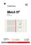
3.3.3.5 Remote Control PCB Design
After all research was done on all of the different components that attached
to processor and the Zigbee chip, a printed circuit board was created. Since
the Zigbee is an RF transceiver, a lot of things had to be considered when
laying out the board. The MRF24J40 Datasheet mentions everything that
should be considered in the designing of a RF board. The datasheet also
provided a suggested layout for the Zigbee chip, so the design that was
approached was to follow Microchips design as closely as possible. The final
layout is shown below in Figure 3.
Figure 3 – Remote Control PCB Design
3.3.4
Control Lamp
3.3.4.1 Power Supply
The power supply for the lamp was designed a lot differently than in the
remote control. The lamps were designed to be plugged into a 120V/60Hz or
240V/50Hz wall socket. So the first step was to send the voltage through a
switch mode power supply, which would cut the voltage down to 12V DC. The
power supply that was chosen was a ETS120400UTC-P5P-SZ made by CUI Inc.
From the datasheet it was found that this power supply could handle currents
of up to 50A. This was a little over kill because currently the LED array draws a
little less than 25A. It was chosen a little high in case more LEDs were needed
8
in the future, which would ultimately draw more current. This power supply
would then output 12V, as stated above, which would be used to drive the
12V LED array. But another step down in voltage was needed before it could
be run to the microprocessors, which ran at 3.3V. To make this step down the
same voltage regulator that was used in the remote control was again used.
3.3.4.2 Bluetooth Module
The Bluetooth module that was chosen was the LMX9830 Bluetooth Serial
Port Module made by National Semiconductor. This Bluetooth module was
chosen because it has its own processor embedded into it. With its own
processor in it, the Bluetooth protocol stack does not have to be loaded onto
the PIC18F87J10 like the Zigbee Stack does. Even though the price of this
Bluetooth module was slightly higher because of the built in processor, it paid
off because it would only be used in one lamp which would prevent the
lighting system to be too expensive.
The Bluetooth module would connect to the microprocessor using a UART
interface. The datasheet of the LMX9830 gives explicit directions on how the
UART is set up. The UART in the LMX9830 supports a four wire connection,
which operates better because it uses two recognition lines. But the LMX9830
can also connect to a two wire UART microprocessor, which the PIC18F87J10
only supports, this information can be found in the LMX9830 – Software Users
Guide. It requires that the Clear To Send (CTS) input to be pulled ground. This
will allow the two processors to properly talk to one another.
This Bluetooth module was used because it creates a Serial Port with another
Bluetooth unit. Once it is connected as a Serial Port with another unit, the
two Bluetooth units can transmit whatever data that is needed.
3.3.4.3 Amplifier Circuit
An amplifier circuit was needed because the PIC18F87J10 outputs 3.3V and
the LEDs run on 12V. This would not allow the LEDs to light up properly
because they would never get to the right voltage level. In order to drive the
LEDs, a N-Channel MOSFET transistor was designed to step up the voltage.
The transistors that were chosen were FDN339AN transistors made by
Fairchild Semiconductor. The datasheet that went along with these transistors
states that they can handle 20V and up to 3A. These transistors had to be
rated high enough to handle the 2.3A draw from LEDs.
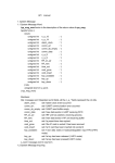
3.3.4.4 LED Array
The LED Array PCB can be seen in Figure 4. Using a set of four high power
MOSFET transistors the current driven through each pair of LED’s can be
controlled. By pulse width modulating the base of each transistor the intensity
of each color can be adjusted. The prototype array contains 8 RGB LEDs used
to demonstrate color changes and ten white LEDs. The white LEDs are not
mounted to the board in Figure 4 due to heat dissipation requirements. In
order to quickly dissipate heat, the white LEDs must be mounted to a
specialized heat sink surface. If mounted to the PCB, the base of the PCB will
likely melt. The white LEDs were mounted directly to the display lamp metal
casing to allow heat dissipation. The white LEDs are connected to the pads
9
shown at the top of the board. Current passes through four current-controlling
resistors before passing through the LEDs. The white LEDs are paired in series
so each of the first five pads shown (from left to right across the top of Figure
4) are connected in series to two white LEDs. Given the variability of the
resistors and LEDs a worst case analysis was performed on this circuit to find
the optimal values and tolerances for the resistors. This analysis can be seen in
Appendix 10.3.
Figure 4 - LED Array
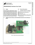
3.3.4.5 Lamp Base PCB
The lamp base printed circuit board was designed much in the same way as
the remote control circuit board. With the development kit that was purchase
for the LMX9830, some of the software that came with the kit provided the
prints for the four layers of the development kit. These prints were replicated
as close as possible just like the PIC18F87J10 and the MRF24J40 were before.
Also, a bit of concern was created by the use of two RF modules on one board.
The solution that was proposed by the team was to put the two RF modules as
far away as possible. From Figure 5, it can be seen that the Bluetooth was
populated near the top left and the MRF24J40 located at the bottom middle
of the board.
10
Figure 5 - Lamp Base
3.3.5 Secondary Lamps
The secondary lamps do not need any more explaining because they are
basically just a striped down Control Lamp. The secondary lamps do not need
a Bluetooth unit because these lamps just rely on the Zigbee modules to
communicate to the rest of the lamp network.
Complications
Two
Display
Lamps
One
Display
Lamp
3.4 Limited by Development Boards, Also see Section 4.3
Original Design
3.4.1
Overview
Figure 2 – Original Design Block Diagram
3.4.2 Remote Control
The remote control was designed to allow the users to communicate to any
11
light in the room from any position he/she is standing. The remote control is a
nice feature to have with this lighting system because it does not limit the user
to any distance from a light, but at the same time, it was designed for limited
operability of the lights.
3.4.2.1 Power Supply
The remote control was designed to use 2 AA batteries, which would produce
a 4.5 V output onto the board. This was a little high because the processor
and Zigbee module were specified to run at 3.3 V. To knock down the voltage
to a tolerable level for the processor to handle, a REG103GA-3.3 linear voltage
regulator was used. The datasheet for this regulator, states that this voltage
regulator can take an input of up to 15 V. This was nice to know because it
can handle the input from the batteries. On an added note, the voltage
regulator can also handle an input of 12 V, which the Lamp Modules run off of.
This voltage regulator is also rated at 500 mA, this is well above the current
that the main processor and the Zigbee processor ever pull.
3.4.2.2 Button Array
In creating a button array for the prototype, the team aimed to create an
intuitive user interface. A power button served as an on/off switch for the
display lamp. Other buttons consisted of three sets of two buttons to increase
or decrease the amount of red, green and blue coloration added to the
emitted light from the lamps. Finally, the remote control had increment and
decrement buttons for the RGB LEDs and for all the white LEDs
simultaneously.
The buttons that were chosen were from ITT Industries, and had the
characteristics of normally open single pole single through buttons, which can
be found on the SPST Momentary Key Switches Datasheet. This allows us to
connect the 3.3V line to one side of the push button and the other side to the
processor, and when pushed the button would allow 3.3V to trigger the
processor.
3.4.2.3 Processor
The processor that was chosen was the PIC18F87J10 made by microchip. This
processor was chosen above other ones mainly because of its five pulse width
modulation outputs, its two UART port modules and it ran on a common 3.3V
input. As the search began for the processor, it was hard to find one with that
many pwm outputs and two UART ports. When the project first began, the
team was under the impression that two UARTs would be needed to connect
to the Bluetooth module and the Zigbee module. This however changed along
the way because it was found out that the Zigbee uses a Serial Port instead of
a UART. The PIC18F87J10 was a very good processor for this project, and it
was decided that it could be used in the remote control and the Lamps. The
button inputs were designed to directly input into 11 different I/O Ports on
the processor.
3.4.2.4 Zigbee Chip
Originally, the Freescale Semiconductor MC13192 was used. This Zigbee chip
seemed to be the best chip that we could use at the time that we researched
12
it. It was found to be able to connect to a large variety of microcontrollers
through a SPI connection, which the PIC18F87J10 supports. So at the time it
was assumed that the Zigbee protocol stack could have been loaded onto the
PIC18F87J10. Although it was assumed that the MC13192 would be able to
work with the PIC18F87J10, it was hard to find support for doing this.
Then around January, another chip made by Microchip was released. The
Zigbee Chip that was selected was the MRF24J40. There was a lot more
support for this chip and Microchip has its own Zigbee Protocol Stack
specifically designed for PIC18F Microcontrollers. The support for loading the
stack onto a PIC18F processor can be found in the AN965: Microchip Stack for
the ZigBee™ Protocol Datasheet. This chip was selected because microchip
fully supports this Zigbee chip with the PIC18F87J10. This Zigbee chip was
designed to connect through the SPI port on the PIC18F87J10 and was also
designed to send out a clock output for the PIC18F87J10 to use.
3.4.2.5 Remote Control PCB Design
After all research was done on all of the different components that attached
to processor and the Zigbee chip, a printed circuit board was created. Since
the Zigbee is an RF transceiver, a lot of things had to be considered when
laying out the board. The MRF24J40 Datasheet mentions everything that
should be considered in the designing of a RF board. The datasheet also
provided a suggested layout for the Zigbee chip, so the design that was
approached was to follow Microchips design as closely as possible. The final
layout is shown below in Figure 3.
Figure 3 – Remote Control PCB Design
3.4.3
Control Lamp
3.4.3.1 Power Supply
The power supply for the lamp was designed a lot differently than in the
remote control. The lamps were designed to be plugged into a 120V/60Hz or
240V/50Hz wall socket. So the first step was to send the voltage through a
switch mode power supply, which would cut the voltage down to 12V DC. The
13
power supply that was chosen was a ETS120400UTC-P5P-SZ made by CUI Inc.
From the datasheet it was found that this power supply could handle currents
of up to 50A. This was a little over kill because currently the LED array draws a
little less than 25A. It was chosen a little high in case more LEDs were needed
in the future, which would ultimately draw more current. This power supply
would then output 12V, as stated above, which would be used to drive the
12V LED array. But another step down in voltage was needed before it could
be run to the microprocessors, which ran at 3.3V. To make this step down the
same voltage regulator that was used in the remote control was again used.
3.4.3.2 Bluetooth Module
The Bluetooth module that was chosen was the LMX9830 Bluetooth Serial
Port Module made by National Semiconductor. This Bluetooth module was
chosen because it has its own processor embedded into it. With its own
processor in it, the Bluetooth protocol stack does not have to be loaded onto
the PIC18F87J10 like the Zigbee Stack does. Even though the price of this
Bluetooth module was slightly higher because of the built in processor, it paid
off because it would only be used in one lamp which would prevent the
lighting system to be too expensive.
The Bluetooth module would connect to the microprocessor using a UART
interface. The datasheet of the LMX9830 gives explicit directions on how the
UART is set up. The UART in the LMX9830 supports a four wire connection,
which operates better because it uses two recognition lines. But the LMX9830
can also connect to a two wire UART microprocessor, which the PIC18F87J10
only supports, this information can be found in the LMX9830 – Software Users
Guide. It requires that the Clear To Send (CTS) input to be pulled ground. This
will allow the two processors to properly talk to one another.
This Bluetooth module was used because it creates a Serial Port with another
Bluetooth unit. Once it is connected as a Serial Port with another unit, the
two Bluetooth units can transmit whatever data that is needed.
3.4.3.3 Amplifier Circuit
An amplifier circuit was needed because the PIC18F87J10 outputs 3.3V and
the LEDs run on 12V. This would not allow the LEDs to light up properly
because they would never get to the right voltage level. In order to drive the
LEDs, a N-Channel MOSFET transistor was designed to step up the voltage.
The transistors that were chosen were FDN339AN transistors made by
Fairchild Semiconductor. The datasheet that went along with these transistors
states that they can handle 20V and up to 3A. These transistors had to be
rated high enough to handle the 2.3A draw from LEDs.
3.4.3.4 LED Array
The LED Array PCB can be seen in Figure 4. Using a set of four high power
MOSFET transistors the current driven through each pair of LED’s can be
controlled. By pulse width modulating the base of each transistor the intensity
of each color can be adjusted. The prototype array contains 8 RGB LEDs used
to demonstrate color changes and ten white LEDs. The white LEDs are not
mounted to the board in Figure 4 due to heat dissipation requirements. In
14
order to quickly dissipate heat, the white LEDs must be mounted to a
specialized heat sink surface. If mounted to the PCB, the base of the PCB will
likely melt. The white LEDs were mounted directly to the display lamp metal
casing to allow heat dissipation. The white LEDs are connected to the pads
shown at the top of the board. Current passes through four current-controlling
resistors before passing through the LEDs. The white LEDs are paired in series
so each of the first five pads shown (from left to right across the top of Figure
4) are connected in series to two white LEDs. Given the variability of the
resistors and LEDs a worst case analysis was performed on this circuit to find
the optimal values and tolerances for the resistors. This analysis can be seen in
Appendix 10.3.
Figure 4 - LED Array
3.4.3.5 Lamp Base PCB
The lamp base printed circuit board was designed much in the same way as
the remote control circuit board. With the development kit that was purchase
for the LMX9830, some of the software that came with the kit provided the
prints for the four layers of the development kit. These prints were replicated
as close as possible just like the PIC18F87J10 and the MRF24J40 were before.
Also, a bit of concern was created by the use of two RF modules on one board.
The solution that was proposed by the team was to put the two RF modules as
far away as possible. From Figure 5, it can be seen that the Bluetooth was
populated near the top left and the MRF24J40 located at the bottom middle
of the board.
15
Figure 5 - Lamp Base
3.4.4 Secondary Lamps
The secondary lamps do not need any more explaining because they are
basically just a striped down Control Lamp. The secondary lamps do not need
a Bluetooth unit because these lamps just rely on the Zigbee modules to
communicate to the rest of the lamp network.
Complications
PCB of
Remote
Device
Nonworking
PCB of
Remote
Device
3.5 No Connection to main MCU, Also see Section 4.3
Original Design
3.5.1
Overview
Figure 2 – Original Design Block Diagram
3.5.2 Remote Control
The remote control was designed to allow the users to communicate to any
16
light in the room from any position he/she is standing. The remote control is a
nice feature to have with this lighting system because it does not limit the user
to any distance from a light, but at the same time, it was designed for limited
operability of the lights.
3.5.2.1 Power Supply
The remote control was designed to use 2 AA batteries, which would produce
a 4.5 V output onto the board. This was a little high because the processor
and Zigbee module were specified to run at 3.3 V. To knock down the voltage
to a tolerable level for the processor to handle, a REG103GA-3.3 linear voltage
regulator was used. The datasheet for this regulator, states that this voltage
regulator can take an input of up to 15 V. This was nice to know because it
can handle the input from the batteries. On an added note, the voltage
regulator can also handle an input of 12 V, which the Lamp Modules run off of.
This voltage regulator is also rated at 500 mA, this is well above the current
that the main processor and the Zigbee processor ever pull.
3.5.2.2 Button Array
In creating a button array for the prototype, the team aimed to create an
intuitive user interface. A power button served as an on/off switch for the
display lamp. Other buttons consisted of three sets of two buttons to increase
or decrease the amount of red, green and blue coloration added to the
emitted light from the lamps. Finally, the remote control had increment and
decrement buttons for the RGB LEDs and for all the white LEDs
simultaneously.
The buttons that were chosen were from ITT Industries, and had the
characteristics of normally open single pole single through buttons, which can
be found on the SPST Momentary Key Switches Datasheet. This allows us to
connect the 3.3V line to one side of the push button and the other side to the
processor, and when pushed the button would allow 3.3V to trigger the
processor.
3.5.2.3 Processor
The processor that was chosen was the PIC18F87J10 made by microchip. This
processor was chosen above other ones mainly because of its five pulse width
modulation outputs, its two UART port modules and it ran on a common 3.3V
input. As the search began for the processor, it was hard to find one with that
many pwm outputs and two UART ports. When the project first began, the
team was under the impression that two UARTs would be needed to connect
to the Bluetooth module and the Zigbee module. This however changed along
the way because it was found out that the Zigbee uses a Serial Port instead of
a UART. The PIC18F87J10 was a very good processor for this project, and it
was decided that it could be used in the remote control and the Lamps. The
button inputs were designed to directly input into 11 different I/O Ports on
the processor.
3.5.2.4 Zigbee Chip
Originally, the Freescale Semiconductor MC13192 was used. This Zigbee chip
seemed to be the best chip that we could use at the time that we researched
17
it. It was found to be able to connect to a large variety of microcontrollers
through a SPI connection, which the PIC18F87J10 supports. So at the time it
was assumed that the Zigbee protocol stack could have been loaded onto the
PIC18F87J10. Although it was assumed that the MC13192 would be able to
work with the PIC18F87J10, it was hard to find support for doing this.
Then around January, another chip made by Microchip was released. The
Zigbee Chip that was selected was the MRF24J40. There was a lot more
support for this chip and Microchip has its own Zigbee Protocol Stack
specifically designed for PIC18F Microcontrollers. The support for loading the
stack onto a PIC18F processor can be found in the AN965: Microchip Stack for
the ZigBee™ Protocol Datasheet. This chip was selected because microchip
fully supports this Zigbee chip with the PIC18F87J10. This Zigbee chip was
designed to connect through the SPI port on the PIC18F87J10 and was also
designed to send out a clock output for the PIC18F87J10 to use.
3.5.2.5 Remote Control PCB Design
After all research was done on all of the different components that attached
to processor and the Zigbee chip, a printed circuit board was created. Since
the Zigbee is an RF transceiver, a lot of things had to be considered when
laying out the board. The MRF24J40 Datasheet mentions everything that
should be considered in the designing of a RF board. The datasheet also
provided a suggested layout for the Zigbee chip, so the design that was
approached was to follow Microchips design as closely as possible. The final
layout is shown below in Figure 3.
Figure 3 – Remote Control PCB Design
3.5.3
Control Lamp
3.5.3.1 Power Supply
The power supply for the lamp was designed a lot differently than in the
remote control. The lamps were designed to be plugged into a 120V/60Hz or
240V/50Hz wall socket. So the first step was to send the voltage through a
switch mode power supply, which would cut the voltage down to 12V DC. The
18
power supply that was chosen was a ETS120400UTC-P5P-SZ made by CUI Inc.
From the datasheet it was found that this power supply could handle currents
of up to 50A. This was a little over kill because currently the LED array draws a
little less than 25A. It was chosen a little high in case more LEDs were needed
in the future, which would ultimately draw more current. This power supply
would then output 12V, as stated above, which would be used to drive the
12V LED array. But another step down in voltage was needed before it could
be run to the microprocessors, which ran at 3.3V. To make this step down the
same voltage regulator that was used in the remote control was again used.
3.5.3.2 Bluetooth Module
The Bluetooth module that was chosen was the LMX9830 Bluetooth Serial
Port Module made by National Semiconductor. This Bluetooth module was
chosen because it has its own processor embedded into it. With its own
processor in it, the Bluetooth protocol stack does not have to be loaded onto
the PIC18F87J10 like the Zigbee Stack does. Even though the price of this
Bluetooth module was slightly higher because of the built in processor, it paid
off because it would only be used in one lamp which would prevent the
lighting system to be too expensive.
The Bluetooth module would connect to the microprocessor using a UART
interface. The datasheet of the LMX9830 gives explicit directions on how the
UART is set up. The UART in the LMX9830 supports a four wire connection,
which operates better because it uses two recognition lines. But the LMX9830
can also connect to a two wire UART microprocessor, which the PIC18F87J10
only supports, this information can be found in the LMX9830 – Software Users
Guide. It requires that the Clear To Send (CTS) input to be pulled ground. This
will allow the two processors to properly talk to one another.
This Bluetooth module was used because it creates a Serial Port with another
Bluetooth unit. Once it is connected as a Serial Port with another unit, the
two Bluetooth units can transmit whatever data that is needed.
3.5.3.3 Amplifier Circuit
An amplifier circuit was needed because the PIC18F87J10 outputs 3.3V and
the LEDs run on 12V. This would not allow the LEDs to light up properly
because they would never get to the right voltage level. In order to drive the
LEDs, a N-Channel MOSFET transistor was designed to step up the voltage.
The transistors that were chosen were FDN339AN transistors made by
Fairchild Semiconductor. The datasheet that went along with these transistors
states that they can handle 20V and up to 3A. These transistors had to be
rated high enough to handle the 2.3A draw from LEDs.
3.5.3.4 LED Array
The LED Array PCB can be seen in Figure 4. Using a set of four high power
MOSFET transistors the current driven through each pair of LED’s can be
controlled. By pulse width modulating the base of each transistor the intensity
of each color can be adjusted. The prototype array contains 8 RGB LEDs used
to demonstrate color changes and ten white LEDs. The white LEDs are not
mounted to the board in Figure 4 due to heat dissipation requirements. In
19
order to quickly dissipate heat, the white LEDs must be mounted to a
specialized heat sink surface. If mounted to the PCB, the base of the PCB will
likely melt. The white LEDs were mounted directly to the display lamp metal
casing to allow heat dissipation. The white LEDs are connected to the pads
shown at the top of the board. Current passes through four current-controlling
resistors before passing through the LEDs. The white LEDs are paired in series
so each of the first five pads shown (from left to right across the top of Figure
4) are connected in series to two white LEDs. Given the variability of the
resistors and LEDs a worst case analysis was performed on this circuit to find
the optimal values and tolerances for the resistors. This analysis can be seen in
Appendix 10.3.
Figure 4 - LED Array
3.5.3.5 Lamp Base PCB
The lamp base printed circuit board was designed much in the same way as
the remote control circuit board. With the development kit that was purchase
for the LMX9830, some of the software that came with the kit provided the
prints for the four layers of the development kit. These prints were replicated
as close as possible just like the PIC18F87J10 and the MRF24J40 were before.
Also, a bit of concern was created by the use of two RF modules on one board.
The solution that was proposed by the team was to put the two RF modules as
far away as possible. From Figure 5, it can be seen that the Bluetooth was
populated near the top left and the MRF24J40 located at the bottom middle
of the board.
20
Figure 5 - Lamp Base
3.5.4 Secondary Lamps
The secondary lamps do not need any more explaining because they are
basically just a striped down Control Lamp. The secondary lamps do not need
a Bluetooth unit because these lamps just rely on the Zigbee modules to
communicate to the rest of the lamp network.
Complications
PCB of
Lamp
Base
Nonworking
PCB of
Lamp
Base
3.6 Short on the Board, Also see Section 4.3 Original
Design
3.6.1
Overview
Figure 2 – Original Design Block Diagram
3.6.2 Remote Control
The remote control was designed to allow the users to communicate to any
21
light in the room from any position he/she is standing. The remote control is a
nice feature to have with this lighting system because it does not limit the user
to any distance from a light, but at the same time, it was designed for limited
operability of the lights.
3.6.2.1 Power Supply
The remote control was designed to use 2 AA batteries, which would produce
a 4.5 V output onto the board. This was a little high because the processor
and Zigbee module were specified to run at 3.3 V. To knock down the voltage
to a tolerable level for the processor to handle, a REG103GA-3.3 linear voltage
regulator was used. The datasheet for this regulator, states that this voltage
regulator can take an input of up to 15 V. This was nice to know because it
can handle the input from the batteries. On an added note, the voltage
regulator can also handle an input of 12 V, which the Lamp Modules run off of.
This voltage regulator is also rated at 500 mA, this is well above the current
that the main processor and the Zigbee processor ever pull.
3.6.2.2 Button Array
In creating a button array for the prototype, the team aimed to create an
intuitive user interface. A power button served as an on/off switch for the
display lamp. Other buttons consisted of three sets of two buttons to increase
or decrease the amount of red, green and blue coloration added to the
emitted light from the lamps. Finally, the remote control had increment and
decrement buttons for the RGB LEDs and for all the white LEDs
simultaneously.
The buttons that were chosen were from ITT Industries, and had the
characteristics of normally open single pole single through buttons, which can
be found on the SPST Momentary Key Switches Datasheet. This allows us to
connect the 3.3V line to one side of the push button and the other side to the
processor, and when pushed the button would allow 3.3V to trigger the
processor.
3.6.2.3 Processor
The processor that was chosen was the PIC18F87J10 made by microchip. This
processor was chosen above other ones mainly because of its five pulse width
modulation outputs, its two UART port modules and it ran on a common 3.3V
input. As the search began for the processor, it was hard to find one with that
many pwm outputs and two UART ports. When the project first began, the
team was under the impression that two UARTs would be needed to connect
to the Bluetooth module and the Zigbee module. This however changed along
the way because it was found out that the Zigbee uses a Serial Port instead of
a UART. The PIC18F87J10 was a very good processor for this project, and it
was decided that it could be used in the remote control and the Lamps. The
button inputs were designed to directly input into 11 different I/O Ports on
the processor.
3.6.2.4 Zigbee Chip
Originally, the Freescale Semiconductor MC13192 was used. This Zigbee chip
seemed to be the best chip that we could use at the time that we researched
22
it. It was found to be able to connect to a large variety of microcontrollers
through a SPI connection, which the PIC18F87J10 supports. So at the time it
was assumed that the Zigbee protocol stack could have been loaded onto the
PIC18F87J10. Although it was assumed that the MC13192 would be able to
work with the PIC18F87J10, it was hard to find support for doing this.
Then around January, another chip made by Microchip was released. The
Zigbee Chip that was selected was the MRF24J40. There was a lot more
support for this chip and Microchip has its own Zigbee Protocol Stack
specifically designed for PIC18F Microcontrollers. The support for loading the
stack onto a PIC18F processor can be found in the AN965: Microchip Stack for
the ZigBee™ Protocol Datasheet. This chip was selected because microchip
fully supports this Zigbee chip with the PIC18F87J10. This Zigbee chip was
designed to connect through the SPI port on the PIC18F87J10 and was also
designed to send out a clock output for the PIC18F87J10 to use.
3.6.2.5 Remote Control PCB Design
After all research was done on all of the different components that attached
to processor and the Zigbee chip, a printed circuit board was created. Since
the Zigbee is an RF transceiver, a lot of things had to be considered when
laying out the board. The MRF24J40 Datasheet mentions everything that
should be considered in the designing of a RF board. The datasheet also
provided a suggested layout for the Zigbee chip, so the design that was
approached was to follow Microchips design as closely as possible. The final
layout is shown below in Figure 3.
Figure 3 – Remote Control PCB Design
3.6.3
Control Lamp
3.6.3.1 Power Supply
The power supply for the lamp was designed a lot differently than in the
remote control. The lamps were designed to be plugged into a 120V/60Hz or
240V/50Hz wall socket. So the first step was to send the voltage through a
switch mode power supply, which would cut the voltage down to 12V DC. The
23
power supply that was chosen was a ETS120400UTC-P5P-SZ made by CUI Inc.
From the datasheet it was found that this power supply could handle currents
of up to 50A. This was a little over kill because currently the LED array draws a
little less than 25A. It was chosen a little high in case more LEDs were needed
in the future, which would ultimately draw more current. This power supply
would then output 12V, as stated above, which would be used to drive the
12V LED array. But another step down in voltage was needed before it could
be run to the microprocessors, which ran at 3.3V. To make this step down the
same voltage regulator that was used in the remote control was again used.
3.6.3.2 Bluetooth Module
The Bluetooth module that was chosen was the LMX9830 Bluetooth Serial
Port Module made by National Semiconductor. This Bluetooth module was
chosen because it has its own processor embedded into it. With its own
processor in it, the Bluetooth protocol stack does not have to be loaded onto
the PIC18F87J10 like the Zigbee Stack does. Even though the price of this
Bluetooth module was slightly higher because of the built in processor, it paid
off because it would only be used in one lamp which would prevent the
lighting system to be too expensive.
The Bluetooth module would connect to the microprocessor using a UART
interface. The datasheet of the LMX9830 gives explicit directions on how the
UART is set up. The UART in the LMX9830 supports a four wire connection,
which operates better because it uses two recognition lines. But the LMX9830
can also connect to a two wire UART microprocessor, which the PIC18F87J10
only supports, this information can be found in the LMX9830 – Software Users
Guide. It requires that the Clear To Send (CTS) input to be pulled ground. This
will allow the two processors to properly talk to one another.
This Bluetooth module was used because it creates a Serial Port with another
Bluetooth unit. Once it is connected as a Serial Port with another unit, the
two Bluetooth units can transmit whatever data that is needed.
3.6.3.3 Amplifier Circuit
An amplifier circuit was needed because the PIC18F87J10 outputs 3.3V and
the LEDs run on 12V. This would not allow the LEDs to light up properly
because they would never get to the right voltage level. In order to drive the
LEDs, a N-Channel MOSFET transistor was designed to step up the voltage.
The transistors that were chosen were FDN339AN transistors made by
Fairchild Semiconductor. The datasheet that went along with these transistors
states that they can handle 20V and up to 3A. These transistors had to be
rated high enough to handle the 2.3A draw from LEDs.
3.6.3.4 LED Array
The LED Array PCB can be seen in Figure 4. Using a set of four high power
MOSFET transistors the current driven through each pair of LED’s can be
controlled. By pulse width modulating the base of each transistor the intensity
of each color can be adjusted. The prototype array contains 8 RGB LEDs used
to demonstrate color changes and ten white LEDs. The white LEDs are not
mounted to the board in Figure 4 due to heat dissipation requirements. In
24
order to quickly dissipate heat, the white LEDs must be mounted to a
specialized heat sink surface. If mounted to the PCB, the base of the PCB will
likely melt. The white LEDs were mounted directly to the display lamp metal
casing to allow heat dissipation. The white LEDs are connected to the pads
shown at the top of the board. Current passes through four current-controlling
resistors before passing through the LEDs. The white LEDs are paired in series
so each of the first five pads shown (from left to right across the top of Figure
4) are connected in series to two white LEDs. Given the variability of the
resistors and LEDs a worst case analysis was performed on this circuit to find
the optimal values and tolerances for the resistors. This analysis can be seen in
Appendix 10.3.
Figure 4 - LED Array
3.6.3.5 Lamp Base PCB
The lamp base printed circuit board was designed much in the same way as
the remote control circuit board. With the development kit that was purchase
for the LMX9830, some of the software that came with the kit provided the
prints for the four layers of the development kit. These prints were replicated
as close as possible just like the PIC18F87J10 and the MRF24J40 were before.
Also, a bit of concern was created by the use of two RF modules on one board.
The solution that was proposed by the team was to put the two RF modules as
far away as possible. From Figure 5, it can be seen that the Bluetooth was
populated near the top left and the MRF24J40 located at the bottom middle
of the board.
25
Figure 5 - Lamp Base
PC
Software
PC
Software
3.6.4 Secondary Lamps
The secondary lamps do not need any more explaining because they are
basically just a striped down Control Lamp. The secondary lamps do not need
a Bluetooth unit because these lamps just rely on the Zigbee modules to
communicate to the rest of the lamp network.
Complications
-
3.6.5 Electrical Requirements
In the Project Proposal and Feasibility Study that the team put together in the fall of 2006, there was a
list of project requirements that would determine the degree of success of the project at the end of
spring 2007. These requirements are listed in Table 3 below.
Table 3 - Electrical Characteristics Requirements Check
Description
Number of total LEDs per lamp
White LEDs per lamp
RGB LEDs per lamp
Max intensity (white LEDs)
Max intensity (RGB LEDs)
Original
Requirement
10
4
6
800 lumens
TBD
Final Prototype
Attribute
18
10
8
500 lumens1
180 lumens2
Max current per white LED
400mA
500mA3
Reason for Change
More Light Output
More Light Output
More Light Output
Requires Less Light
Changed to Accent
Lighting
Increased Tolerances
1
(Osram) Golden Dragon Datasheet
(Osram) Tri-color LED Datasheet
3
(Osram) Golden Dragon Datasheet
2
26
Description
Original
Requirement
50mA
~25W
Final Prototype
Attribute
70mA4
23W
256
Continuous
256
16 Segments
Continuous operating Voltage
Temperature
Frequency
Common voltage
Common current
90VAC – 250VAC
-10degC – 65degC
40Hz – 70Hz
5 VDC +/-5%
5A max
100VAC – 240VAC5
-10degC – 70degC6
47Hz – 63Hz7
12VDC8
1.58A
White voltage
White current per LED
25V max
400mA max
12V9
157mA10
RGB voltage
RGB current
25V max
500mA max
continuous
Windows XP
Bluetooth
10 meters
(30 feet)
10 meters
(30 feet)
Zigbee
On/Off, Color,
Intensity
12V
57.5mA11
Max current per RGB LED
Lamp total power
consumption
Estimated number of colors
Dimming variability
Operating System
PC Wireless Protocol
PC Operating distance
Remote Operating distance
Remote Wireless Protocol
Remote Functions
Windows XP
Bluetooth
10 meters
(30 feet)
10 meters
(30 feet)
Zigbee
On/Off, Color, Intensity
Reason for Change
Increased Tolerances
Lower Power
Consumption
Simplifies Design while
still maintaining
appearance
Tighter Specs on Parts
Tighter Specs on Parts
Tighter Specs on Parts
More Light Output
Lower Power
Consumption
Fit to New Design
Lower Power
Consumption
Fit to New Design
Lower Power
Consumption
-
Some of the major changes to electrical characteristics occurred in the power consumption. Most
notable was the change in the number of LEDs to use, which went from 4 white and 6 tri-colors to 10
white and 8 tri-color LEDs. However, the power consumption went from an estimated 25W to 23W,
which ties directly into our design goal of making an efficient and low power lamp.
4
(Osram) Tri-color LED Datasheet
(CUI Inc.) Power Supply Datasheet
6
(CUI Inc.) Power Supply Datasheet
7
(CUI Inc.) Power Supply Datasheet
8
(CUI Inc.) Power Supply Datasheet
9
(CUI Inc.) Power Supply Datasheet
10
(Osram) Golden Dragon Datasheet
11
(Osram) Tri-color LED Datasheet
5
27
3.7 Production Design Requirements
The prototype built by Team LEDmote is designed to lead into a production phase implemented by
Innotec.
3.7.1 PC Requirements
Please refer to the LEDmote PC Control Console User Manual to determine production requirements for
the PC.
3.7.2 Electrical Requirements
Some flexibility was allowed in the production design electrical requirements to adjust the intensity of
the LEDs. However it was assumed that once a base current had been chosen, little deviation would
occur from this set current so that all intensity adjustments were implemented through the PWM
instructions of the MCU. As can be seen in Table 3, the prototype common current was set at 1.58A,
although this can be adjusted up to a maximum of 5A depending on the product’s unique
requirements12. The voltage across the LEDs should not exceed 25V.
3.7.3 LED Enclosure Requirements
While building the prototype, Team LEDmote did not study in depth the casing and reflective elements
of a production system. There are many varieties of lamp fixtures that could potentially be designed to
house the LEDs of each lamp module. In the case of room lighting, such fixtures should be used to
distribute and diffuse the light evenly throughout a room. In both the room lighting case and the direct
lighting case (for example – in the use of the system in a desk lamp) direct exposure of the eyes to the
LEDs should be avoided.
From informal tests run on the prototype lamp, the team determined that a user should not to look
directly at white LEDs running with a current greater than 500mA13. At this current, repeated exposure
to the intensity of the light could cause some health risks and in the short term will likely cause some
discomfort to the user. The team did not determine a maximum current for the RGB LEDs as all tested
currents did not approach an intensity that caused any measure of discomfort.
3.7.4 Lamp Spacing Requirements
Test runs on the prototype indicated that the lamp’s light, even when reflected, was clearly visible from
distances of over 300ft. In production design of room lamps, the team recommends that the LEDs be
directed downward in multiple directions through a transparent diffuser. The team recommends that
lamps be spaced no more than 30ft apart to provide adequate lighting to the room. However, the lamps
may be spaced at distances of up to 250ft (direct line of sight) if necessary. Spacing of lamps is limited
only by the range of travel of Zigbee electromagnetic waves and the interference they encounter. Refer
to Section 7.1.3 for documentation on testing of Zigbee communication in various environments. The
current system can implement up to 180 separate Zigbee-equipped modules14.
12
(OSRAM)
(OSRAM)
14
(Microchip Technology Inc.)
13
28
The system requires that each lamp module be connected to a supply source. It is assumed that most
production systems will use a mains voltage supply from a building’s electrical system. However, the
system should function normally if an alternative supply such as a generator or battery were to be used
provided that such alternative supplies met the remaining electrical requirements. Each lamp must be
provided with a 12VDC minimum common voltage to ensure proper operation. In the original design and
in production this is provided by connecting a mains supply through a switch-mode power supply
mounted directly to the lamp PCB. In the secondary design (and the prototype) the DC voltage was
provided by Agilent E3620A and Hewlett Packard E3611A power supplies.
4 The Design
4.1 Design Overview
The design strategy used in the past semester was focused on getting a working prototype for Innotec to
build upon when the project is continued by their engineers.
4.2 Design Decisions
4.2.1 Lamp Module Decision
The decision matrix, shown in Table 5.8, discusses the different alternatives on how the remote controls
multiple lamps. The team decided that the remote would regulate all the lamp modules at the same
time. Allowing the remote control to individually manipulate different lamps in the area was too
complicated to fit into a single remote while still providing an ease of use to the consumer. The
alternative was to create a lighting schedule with the remote control. This alternative did not stand up
to other alternatives, adding unnecessary complexity to the remote control, and so increasing its cost.
8
5
4
2
5
4
6
8
Totals
7
Flexibility
3
Reliability
7
Low Power
User Friendliness
10
Low Cost
Size
Table 4.1 - Lamp Module Alternatives Decision Matrix
Weights (out of 10)
Lamp Module Alternatives
Individual Lamp Modules
185
29
All Lamp Modules at Once
Scheduler Control
9
2
7
5
7
5
8
3
7
5
3
7
287
166
4.2.2 Lighting Decisions
While the actual market-product LEDs will be provided by Innotec, the team felt it was necessary for the
remote control decision matrix (and subsequent control decisions) to examine the alternatives for LED
lighting given the project requirements. The decision matrix, shown in Table 5.7, weighs the different
lighting techniques of the Red Green Blue (RGB) LEDs and white LEDs. More specifically, it raises the
question of how many different colors the remote control will offer and what range of dimming
capabilities it can provide. Both of these options deal with how the remote control will increase the
color or brightness level. This issue was not a problem for the remote because it has three different
color buttons, each controlling one of the three colors in the RGB LED. It then sends out an up or down
signal of the specific color pressed. The two different alternatives were weighted closely in the end
because no significant additional design was needed to add more colors. The processor received a signal
through the wireless transmitting device to increase the color by a certain increment for each button
pressed.
Size
User Friendliness
Low Power
Reliability
Flexibility
10
7
3
7
8
5
Limited Color Option
256 Color Option
Limited Dimming Option
8
6
8
7
7
7
4
7
4
8
7
6
7
6
7
3
10
2
268
277
249
Continuous Dimming
7
5
7
6
5
9
253
Totals
Low Cost
Table 4.2 - Lighting Alternatives Decision Matrix
Weights (out of 10)
Lighting Alternatives
4.2.3 Button Decision
This decision matrix, shown in Table 5.6, deals with the physical buttons of the remote control. For this
project, three possible input devices were chosen: slides, individual buttons, and a scroll wheel. These
30
three options are shown below in Table 5.6, and weighted according to the criteria discussed above. The
button alternative ended up slightly higher than the other two options because of its reliability. A slider
has a preset position, which is a disadvantage if, when the lighting system is initially turned on, the lights
automatically turn on to whatever preset position the slider is in. A user may not want the lights to be
fully bright or fully dark when the lighting system is first turned on. The advantage of the other button
systems is that, when the lighting system is turned on, it sets to a default medium brightness that can be
adjusted up or down. There are no physical limitations on the button or scroll wheel system over the
slider system. The main advantage of a button system over a scroll wheel system is minimization of
costs.
Size
User Friendliness
Low Power
Reliability
Flexibility
10
7
3
7
8
5
7
6
3
7
5
6
7
7
7
6
7
7
5
8
7
6
8
9
Totals
Low Cost
Table 4.3 - Button Alternatives Decision Matrix
Weights (out of 10)
Button Alternatives
Slides
Individual Buttons
Scroll Wheel (like iPOD)
252
269
243
4.2.4 Amplifier Decision
In researching the amplifier alternatives15 and in discussions with Mr. Veenstra, the team determined
that an ideal solution could be reached by using a combination of the first and third alternatives, i.e.
using a high power transistor to output the necessary current together with PWM to vary the
brightness.
15
All About Circuits, PWM power controller. 2003
<http://www.allaboutcircuits.com/vol_6/chpt_6/9.html>
31
Flexibility of overall design
Size and Complexity
Availability
Reliability
8
9
7
5
10
6
4
8
8
7
5
8
8
8
3
289
209
9
8
9
10
10
357
Totals
Low Cost
Table 4.4 - Amplifier Decision Matrix
Weights (out of 10)
Switch Alternatives
High-power transistor
Operational
Amplifier/DCP
Pulse Modulation
4.2.5 Power Decision
Similarly to the decision matrix for the control system, the power system decision matrix showed very
little difference between the two options. A centralized system is probably more cost-effective than a
distributed system because it minimizes the number of power supplies. The team chose to use
distributed power supplies on each of the lamp modules, since a centralized power supply would require
the technicians who installed the lighting system to do additional wiring beyond that which the room
already contains.
By using a system that has both distributed power and distributed control, the overall lighting system
has maximum flexibility. Lamp modules could be designed not just as individual lighting units in rooms
but could be used almost anywhere in a room (for example, as a desk lamp).
flexibility of overall design
size
reliability
10
10
9
9
Totals
low cost
Table 4.5 - Power Decision Matrix
Weights (out of 10)
Switch Alternatives
32
Distributed
Centralized
5
7
8
4
6
8
7
7
247
245
4.2.6 System Decision
The decision matrix analysis shows that the pros and cons of each system were nearly balanced. The
distributed control alternative provides the greatest amount of flexibility but the cost of installing a
control in every fixture was cost inefficient. The centralized control option had the advantage of
minimizing the necessary number of system processors and therefore reducing cost. However,
centralized control reduces the flexibility of the project by forcing physical wiring to be installed
between the control circuitry and the lamp modules. This seemed somewhat counter-intuitive to the
team’s objective of creating a wireless lighting system. Hence, despite distributed control only
marginally beating out centralized control, the team chose a distributed control system for their design.
flexibility of overall design
size
reliability
7
10
9
9
5
7
8
4
6
8
7
7
Totals
low cost
Table 4.6 - Control Decision Matrix
Weights (out of 10)
Switch Alternatives
Distributed
Centralized
232
224
4.2.7 Switch Decision
Wall-mounted switches controlled the power feed to all lamp modules. This provided a basic
functionality in the event of failure or absence of wireless devices such as the remote control, laptop or
in-room computer. The manual switching functionality was deemed essential for emergency cases.
However, other functions of the lamp modules such as variable brightness and color were not built into
the wall switches. Adding these features to a wall-mounted switch decreased the need for a wireless
controller such as a remote or laptop. Thus the associated flexibility was reduced. The software and
remote provided an on-off function for the lamp modules without the use of wall-mounted switches.
33
flexibility of overall design
user friendliness
availability
reliability
9
9
10
7
10
9
6
9
4
8
7
8
6
10
9
Totals
low cost
Table 4.7 - Wall Switch Decision Matrix
Weights (out of 10)
Switch Alternatives
Simple on/off switch
Switch
with
all
features
398
292
4.3 Original Design
4.3.1
Overview
Figure 2 – Original Design Block Diagram
4.3.2 Remote Control
The remote control was designed to allow the users to communicate to any light in the room from any
position he/she is standing. The remote control is a nice feature to have with this lighting system
because it does not limit the user to any distance from a light, but at the same time, it was designed for
limited operability of the lights.
34
4.3.2.1 Power Supply
The remote control was designed to use 2 AA batteries, which would produce a 4.5 V output onto the
board. This was a little high because the processor and Zigbee module were specified to run at 3.3 V.
To knock down the voltage to a tolerable level for the processor to handle, a REG103GA-3.3 linear
voltage regulator was used. The datasheet16 for this regulator, states that this voltage regulator can
take an input of up to 15 V. This was nice to know because it can handle the input from the batteries.
On an added note, the voltage regulator can also handle an input of 12 V, which the Lamp Modules run
off of. This voltage regulator is also rated at 500 mA, this is well above the current that the main
processor and the Zigbee processor ever pull.
4.3.2.2 Button Array
In creating a button array for the prototype, the team aimed to create an intuitive user interface. A
power button served as an on/off switch for the display lamp. Other buttons consisted of three sets of
two buttons to increase or decrease the amount of red, green and blue coloration added to the emitted
light from the lamps. Finally, the remote control had increment and decrement buttons for the RGB
LEDs and for all the white LEDs simultaneously.
The buttons that were chosen were from ITT Industries, and had the characteristics of normally open
single pole single through buttons, which can be found on the SPST Momentary Key Switches
Datasheet17. This allows us to connect the 3.3V line to one side of the push button and the other side to
the processor, and when pushed the button would allow 3.3V to trigger the processor.
4.3.2.3 Processor
The processor that was chosen was the PIC18F87J10 made by microchip. This processor was chosen
above other ones mainly because of its five pulse width modulation outputs, its two UART port modules
and it ran on a common 3.3V input. As the search began for the processor, it was hard to find one with
that many pwm outputs and two UART ports. When the project first began, the team was under the
impression that two UARTs would be needed to connect to the Bluetooth module and the Zigbee
module. This however changed along the way because it was found out that the Zigbee uses a Serial
Port instead of a UART. The PIC18F87J10 was a very good processor for this project, and it was decided
that it could be used in the remote control and the Lamps. The button inputs were designed to directly
input into 11 different I/O Ports on the processor.
4.3.2.4 Zigbee Chip
Originally, the Freescale Semiconductor MC13192 was used. This Zigbee chip seemed to be the best
chip that we could use at the time that we researched it. It was found to be able to connect to a large
variety of microcontrollers through a SPI connection, which the PIC18F87J10 supports. So at the time it
was assumed that the Zigbee protocol stack could have been loaded onto the PIC18F87J10. Although it
was assumed that the MC13192 would be able to work with the PIC18F87J10, it was hard to find
support for doing this.
16
17
(Texas Instruments Incorporated)
(ITT Industries)
35
Then around January, another chip made by Microchip was released. The Zigbee Chip that was selected
was the MRF24J40. There was a lot more support for this chip and Microchip has its own Zigbee
Protocol Stack specifically designed for PIC18F Microcontrollers. The support for loading the stack onto
a PIC18F processor can be found in the AN965: Microchip Stack for the ZigBee™ Protocol Datasheet18.
This chip was selected because microchip fully supports this Zigbee chip with the PIC18F87J10. This
Zigbee chip was designed to connect through the SPI port on the PIC18F87J10 and was also designed to
send out a clock output for the PIC18F87J10 to use.
4.3.2.5 Remote Control PCB Design
After all research was done on all of the different components that attached to processor and the Zigbee
chip, a printed circuit board was created. Since the Zigbee is an RF transceiver, a lot of things had to be
considered when laying out the board. The MRF24J40 Datasheet19 mentions everything that should be
considered in the designing of a RF board. The datasheet also provided a suggested layout for the
Zigbee chip, so the design that was approached was to follow Microchips design as closely as possible.
The final layout is shown below in Figure 3.
Figure 3 – Remote Control PCB Design
4.3.3
Control Lamp
4.3.3.1 Power Supply
The power supply for the lamp was designed a lot differently than in the remote control. The lamps
were designed to be plugged into a 120V/60Hz or 240V/50Hz wall socket. So the first step was to send
the voltage through a switch mode power supply, which would cut the voltage down to 12V DC. The
power supply that was chosen was a ETS120400UTC-P5P-SZ made by CUI Inc. From the datasheet20 it
was found that this power supply could handle currents of up to 50A. This was a little over kill because
18
(Microchip Technology Inc.)
(Microchip Technologies Inc.)
20
(CUI Inc.)
19
36
currently the LED array draws a little less than 25A. It was chosen a little high in case more LEDs were
needed in the future, which would ultimately draw more current. This power supply would then output
12V, as stated above, which would be used to drive the 12V LED array. But another step down in
voltage was needed before it could be run to the microprocessors, which ran at 3.3V. To make this step
down the same voltage regulator that was used in the remote control was again used.
4.3.3.2 Bluetooth Module
The Bluetooth module that was chosen was the LMX9830 Bluetooth Serial Port Module made by
National Semiconductor. This Bluetooth module was chosen because it has its own processor
embedded into it. With its own processor in it, the Bluetooth protocol stack does not have to be loaded
onto the PIC18F87J10 like the Zigbee Stack does. Even though the price of this Bluetooth module was
slightly higher because of the built in processor, it paid off because it would only be used in one lamp
which would prevent the lighting system to be too expensive.
The Bluetooth module would connect to the microprocessor using a UART interface. The datasheet21 of
the LMX9830 gives explicit directions on how the UART is set up. The UART in the LMX9830 supports a
four wire connection, which operates better because it uses two recognition lines. But the LMX9830 can
also connect to a two wire UART microprocessor, which the PIC18F87J10 only supports, this information
can be found in the LMX9830 – Software Users Guide22. It requires that the Clear To Send (CTS) input to
be pulled ground. This will allow the two processors to properly talk to one another.
This Bluetooth module was used because it creates a Serial Port with another Bluetooth unit. Once it is
connected as a Serial Port with another unit, the two Bluetooth units can transmit whatever data that is
needed.
4.3.3.3 Amplifier Circuit
An amplifier circuit was needed because the PIC18F87J10 outputs 3.3V and the LEDs run on 12V. This
would not allow the LEDs to light up properly because they would never get to the right voltage level. In
order to drive the LEDs, a N-Channel MOSFET transistor was designed to step up the voltage. The
transistors that were chosen were FDN339AN transistors made by Fairchild Semiconductor. The
datasheet23 that went along with these transistors states that they can handle 20V and up to 3A. These
transistors had to be rated high enough to handle the 2.3A draw from LEDs.
4.3.3.4 LED Array
The LED Array PCB can be seen in Figure 4. Using a set of four high power MOSFET transistors the
current driven through each pair of LED’s can be controlled. By pulse width modulating the base of each
transistor the intensity of each color can be adjusted. The prototype array contains 8 RGB LEDs used to
demonstrate color changes and ten white LEDs. The white LEDs are not mounted to the board in Figure
4 due to heat dissipation requirements. In order to quickly dissipate heat, the white LEDs must be
mounted to a specialized heat sink surface. If mounted to the PCB, the base of the PCB will likely melt.
21
(National Semiconductor Co.)
(National Semiconductor Co.)
23
(Fairchild Semiconductor)
22
37
The white LEDs were mounted directly to the display lamp metal casing to allow heat dissipation. The
white LEDs are connected to the pads shown at the top of the board. Current passes through four
current-controlling resistors before passing through the LEDs. The white LEDs are paired in series so
each of the first five pads shown (from left to right across the top of Figure 4) are connected in series to
two white LEDs. Given the variability of the resistors and LEDs a worst case analysis was performed on
this circuit to find the optimal values and tolerances for the resistors. This analysis can be seen in
Appendix 10.3.
Figure 4 - LED Array
4.3.3.5 Lamp Base PCB
The lamp base printed circuit board was designed much in the same way as the remote control circuit
board. With the development kit that was purchase for the LMX9830, some of the software that came
with the kit provided the prints for the four layers of the development kit. These prints were replicated
as close as possible just like the PIC18F87J10 and the MRF24J40 were before. Also, a bit of concern was
created by the use of two RF modules on one board. The solution that was proposed by the team was
to put the two RF modules as far away as possible. From Figure 5, it can be seen that the Bluetooth was
populated near the top left and the MRF24J40 located at the bottom middle of the board.
38
Figure 5 - Lamp Base
4.3.4 Secondary Lamps
The secondary lamps do not need any more explaining because they are basically just a striped down
Control Lamp. The secondary lamps do not need a Bluetooth unit because these lamps just rely on the
Zigbee modules to communicate to the rest of the lamp network.
4.4 Complications
The original plan had some significant complications caused both by the design and fabrication of the
PCBs.
4.4.1 Remote Complications
In the Remote Control Circuit, the MCU received an oscillating external signal from the Zigbee
transceiver clock. The Zigbee transceiver outputs a clock signal with a frequency of 2.5MHz, which is
below the minimum input clock rate for the MCU of 10MHz.24 Therefore; the MCU was unable to
function properly and did not acknowledge itself when contacted by the ICD2 programmer.
“In EC mode the 2.5MHz crystal can be run, but only thing is that few of the peripherals may run very
slow.” 25
This quote from Microchip support and data from the Microchip data sheet26 lead the team to believe
that correct connection to the chip was not attainable while receiving a 2.5MHz clock from the Zigbee
module. The chip ran properly, as detected from the clock division output. This output provided a ¼
frequency output clock, which was successfully determined through views on an oscilloscope. All VCC
inputs were receiving proper voltages and all GND inputs were grounded. However when addressed by
the program, the chip did not respond with an identification code, as the chip on the development
board did.
24
(Microchip Technology Inc.)
Support Response 4/6/2007 4:09 AM – Microchip Support
26
(Microchip Technologies Inc.)
25
39
4.4.2 Lamp Base Complications
The Lamp Base also had the same issues that were designed into the remote board. Also, the lamp base
had a short underneath the Bluetooth chip. This chip was a 60 pin Ball grid array (BGA) measuring 6mm
by 9mm, leaving very little room for error. As the soldering paste melted beneath the chip, it was
determined that a solder bridge was formed across pins that are connected to power and ground. This
caused the board to not power up properly and tests showed that this weak power signal was
insufficient to supply the microcontroller.
4.4.3 Complications Conclusion
Because of the previously mentioned complications, the original plan had to be put aside in favor of the
secondary plan. The secondary plan was then implemented because it implemented the use of key
hardware predesigned and prefabricated in the form of development kits.
4.5 Final Prototype
The final prototype had three modules to it the remote control, control lamp and a computer program.
The prototype block diagram can be seen below in Figure 6. The red blocks represent the portions that
were added to the design and the orange blocks represent the parts that were just modified or swapped
out for different components. The following sections lay out the decisions, hardware and software of
the final prototype.
Figure 6 – Prototype Block Diagram
4.5.1
Hardware Solution
4.5.1.1 Development Kits
In implementing hardware, the team chose to use two different development kits provided by
Microchip. The first was the HPC Explorer board, which included a PIC18F8722, convenient connectors
for programming and I/O, LEDs, a 10MHz crystal and several buttons. The team used the HPC board as a
central controller that could take Zigbee-communicated inputs from the remote control as well as
40
Bluetooth-communicated inputs from the PC while outputting a signal to light up the specified LEDs. The
second development kit was the PICDEM Z, two of which were used in the secondary design. The
PICDEM Z board is a recent design by Microchip, created specifically for testing communication through
Zigbee. One of the boards was used as a basis for the remote control while the other was used to
communicate with the HPC board via UART hardwired connections. The PICDEM Z has a PIC18LF4620
processor, a MRF24J40 transceiver daughter card and many similar features to the HPC board.
4.5.1.2 Remote Control
The prototype remote control was made up of bread-boarded components. A remote control PCB was
designed and populated for demonstration. Unfortunately, it only had partial functionality, so the team
decided it should not be used. The likely cause of malfunction was the difficulties in soldering the parts
to the board, resulting in some components not making a clean electrical connection to the rest of the
circuit.
Figure 7 - Prototype Remote Control PCB Layout
4.5.1.2.1 Button Array
The power button was placed at the upper left corner of the remote (as it lay in the user’s hand) – a
standard position for an on/off switch in many remote controllers. The increment buttons for the red,
green and blue colors were placed above the decrement buttons. The increment buttons for the all color
and white were placed on the right side, while the decrement was placed on the left. The team felt that
this was the most intuitive layout. This layout can be seen in Figure 7.
The team chose to use small, round buttons for the prototype to minimize space requirements on the
remote control. Red, Green and Blue buttons were selected to correspond to the red, blue and green
color increases. White buttons were designated to represent increases and decreases in white color.
Black buttons were designated to represent increases and decreases in all three colors. A yellow button
was selected as a power button.
41
4.5.1.2.2 Encoder
The team chose to use an MM74C922 encoder chip27 after realizing that a compatibility issue had arisen.
The remote control needed to have 11 input buttons to the PIC18F4620 processor, but the processor
only had 4 inputs. The encoder’s main function was to serve as a matrix so that the correct signals would
be passed to the processor. The selected encoder also had an inbuilt debouncer, which circumvented
the difficulties the team had previously experienced with bouncing. The encoder datasheet showed a
simple design for asynchrous data entry onto a bus, providing a very similar circuit to our needs. This
circuit included an oscillator function using a capacitor connected to ground and an inverter set up on
the Data Available pin to set up the Output Enable pin so that the encoder signals could be read by the
processor.
4.5.1.2.3 Inverter
The team found it necessary to include an inverter chip in the remote control design because the
processor recognized a change to a low voltage from a default high voltage while the encoder output a
higher voltage upon a button push input. The MM74C04N inverter chip28 was chosen as it was readily
available and appeared to function effectively. The team discovered that the inverter worked most
effectively when the output from the encoder was tied to a pull-down resistor so that the current
reaching the inverter was low. In the prototype, these pull-down resistors had a value of 10MΩ.
4.5.1.2.4 PIC18F4620
In the prototype of our design, the PIC18F462029 was used as part of the PICDEM Z30 development kit.
The original design called for the PIC18F87J10 processor, but the -4620 came pre-installed in the
development kit and so the team chose to do some research on this processor and use it instead of the 87J10 in the remote control. The -4620 on the development kit came with the hardware necessary to
take inputs and then output to the Zigbee daughter card31.
4.5.1.3 Lamp Base
4.5.1.3.1 Amplifier
The amplifier circuit was designed to amplify the signal from the microprocessor to the LEDs. Since the
processor only outputs a voltage of 3.3V and the LEDs required a higher voltage to operate correctly,
selecting the correct amplifier circuitry proved important.
27
(Fairchild Semiconductor)
(Fairchild Semiconductor)
29
(Microchip Technology Inc.)
30
(Microchip Technology Inc.)
31
(Microchip Technology Inc.)
28
42
Figure 8 - Prototype Amplifier PCB
The amplifier circuit consisted of 4 inputs from the PIC18F87J10 processor, resistors, transistors and
output pins. The transistors were used as the actual amplifiers that allow for adjustments in the LEDs.
The resistance of the gate resistors was required to be greater than Rmin in order to limit the output
current of the Microcontroller. The calculation of Rmin is seen in Figure 9.
Figure 9 - Rmin Calculation
With a MOSFET transistor, shown in Figure 11, the gate and source together was modeled as a
capacitor. This created an RC circuit, which dampened the PWM if the RC time constant was low
enough. To ensure that this did not occur, the RC time constant was set to be a factor of 10 less than
the period of the PWM. The following equations calculated Rmax as a result of these considerations.
Figure 10 - Rmax Calculation
Considerations for the transistors in the design of the Amplifier Circuit were such that they must handle
the drain-to-source voltage so that the transistors were not destroyed by overly high currents. The
resistors are rated at 10kΩ - a value assigned because it was between Rmin and Rmax. Also, the
43
transistors must be activated by a 3.3V gate-to-source voltage, because this was what the chip driving
the amplifier was able to produce.
Figure 11 - MOSFET Transistor
4.5.1.3.2 Display Lamp
The display lamp came with a mounted switch as an example of the wall-mounted switch as described in
Section 4.2.7. The LED Array PCB was mounted in an orientation such that white light reflected
effectively off the white paper backing of the display lamp and also off of the diamond-plated steel used
to shield observers from direct eye contact with the white LEDs. Additionally, two semicircular sheets of
plastic were inserted in the steel plating to distinguish the color LED operation from the white LEDs. The
display lamp (in operation) can be seen in Figure 12.
44
Figure 12 - Display Lamp
4.5.2
Software Solution
4.5.2.1 PC Software
As discussed in the Business Plan section, the operating system used for the design of the software was
Windows XP. The prototype was designed on Windows XP SP2.
4.5.2.1.1 Programming Language
4.5.2.1.1.1 Criteria
Selecting an appropriate software programming language was vital to time expenses and functionality. If
an unfamiliar language was selected, then more time must be spent in familiarization with the language.
If a tedious language was selected, more time must be spent in programming the intricacies of the
language. Therefore, one heavily weighted criterion was how familiar the team was with the language.
This was measured as the amount of previous experience team members had with each language. It was
considered whether or not the language was adequate to fulfill the desired functions of software for this
project. The software needed to interface with a Bluetooth card. The capability to create a graphical
user interface (GUI) that is transparent to the user was also required. It had to be capable of creating
applications compatible with Windows; because that was the OS we intended to install our prototype
software on. Without adequate software no matter how familiar the team was with the language,
certain functions could not be created. Another criterion was an adequate support system to answer all
programming queries. In summary, the criteria were previous experience, functional Bluetooth
interface, capacity to create transparent GUI, ability to create windows compatible applications, and an
adequate support system.
45
4.5.2.1.1.2 Alternatives
There were three alternatives considered for software programming language. The alternatives were
Java, C++, and Basic. Java is an object-oriented programming language developed by Sun Microsystems.
It was designed to be executed on multiple operating systems. It was also designed for using computer
networks.32 C++ is a high-level programming language originally developed by Bell Labs.33 Basic stands
for “Beginner’s All-purpose Symbolic Instruction Code” and originated at Dartmouth College. It was
created as a programming language for the non-technical user.34
4.5.2.1.1.3 Decision
The decision matrix in Table 4.8 shows Visual Basic as the superior programming language choice for
software development. The major factor in making this decision was that the team had more collective
experience in coding Visual Basic. This included having two year intern work experience with Visual Basic
software. Other factors that supported this decision were the extensive support structure available on
MSDN (Microsoft Developer Network). MSDN has extensive resources in developing software with
specific applications for windows, developing GUI, and interfacing to Bluetooth.35 Java has a wide
variety of applications and all the required capabilities. However, the team’s unfamiliarity with the
language and its unknown complexities ruled Java out as an acceptable alternative. Although the team
has had two classes on C++, the experience and ease of use of Visual Basic ruled out the use of C++.
Totals
Support System
Windows
Development
GUI
Development
Interface
Bluetooth
Previous
Experience
to
Table 4.8 – Programming Language Decision Matrix
Weights (out of 10)
7
10
8
6
7
Java
3
8
8
9
7
268
C++
3
10
8
9
10
309
Basic
9
10
9
5
9
328
IDE
32
Java
(Programming
Language).
Wikipedia,
7
<http://en.wikipedia.org/wiki/Java_%28programming_language%29>
33
C++. Wikipedia, 7 December 2006. <http://en.wikipedia.org/wiki/C%2B%2B>
34
BASIC. Wikipedia, 7 December 2006. <http://en.wikipedia.org/wiki/BASIC>
35
MSDN. 7 December 2006. <http://msdn2.microsoft.com/en-us/default.aspx >
December
2006.
46
4.5.2.1.2 Software Design
4.5.2.1.2.1 Software Architecture
The software architecture, shown in Figure 13, was the hierarchy leading from the user interface to the
Bluetooth module.
G UI
Windows AP I
B luetooth Driver
B luetooth Hardware
Figure 13 - Software Architecture
The GUI received input and displayed output directly to the user. When receiving an input from the user,
the GUI transfered it through a Windows API to the Bluetooth Driver and directed the Bluetooth
hardware to send the desired instruction. The instruction was decoded in the hardware by the controller
and pulses were sent to LEDs. When a command was received by the controller from the remote, it
relays onto other Zigbee devices and relayed back through Bluetooth transmission to the laptop
controller. When received by the Bluetooth hardware on the laptop, the signal percolated back up the
hierarchy and was reflected in the GUI by a change in either the color selected or white LED intensity
setting.
47
4.5.2.1.2.2
GUI Layout
Figure 14 - GUI Layout
The concept of the GUI is illustrated in Figure 1Figure 14. All features of the GUI are subject to change.
The GUI will vary greatly depending on the environment and size of the lighting system. The functions
and user operation are explained in detail in the LEDmote PC Console Version 1.0 User Manual36.
36
(Veldkamp)
48
4.5.2.1.2.3
GUI Architecture
Figure 15 - Overall System Software Flow Diagram
The GUI software interface consisted of five user forms and layouts. When the user double clicks the
executable file, the interface opens into the credit dialog screen. Throughout the duration of this screen,
a number of actions are performed in the system. The breakdown of these actions is shown in Figure 15.
The entire system can be broken down into process flow diagrams. All of the variables were stored in a
large array. This array contained all the information for each individual lamp. The breakdown of the
array components are listed below in Figure 16.
49
Figure 16 - System Array Settings
Each function and control in Figure 15 was broken down into the sections below to explain their
function and codes.
4.5.2.1.2.3.1 CREDIT DIALOG
Figure 17 - Credit Dialog Form Process Flow
50
During the credit dialog process flow the program began by loading the data.txt file into the
system array. An excerpt from the data.txt file is pasted below:
#0#18#0#255#128#0#False#False#False#False#False#0#18#0#255#128#0#False#False#F
alse#False#False#0#18#0#255#128#0#False#False# …
The system array was set up as the storage structure for the lamp settings and values. The “#”
was used as the delimiter separating the variables. Once this file was loaded into the array, the
credit dialog activates a search for local Bluetooth devices in the computers area. A list of
Bluetooth devices was compiled and compared to the stored master lamp name. If no device
was found that matches the master lamp name, or no master lamp has been previously
designated a list of potential devices was displayed to the user. Once the master lamp was
found and/or chosen the program retrieved information from all the lamps. The lamps current
settings were downloaded into the array and variables such as the number of lamps were set.
Finally the credit dialog screen was hidden and the control form was loaded.
4.5.2.1.2.3.2 CONTROL FORM
The control form took the variables and array set by the credit dialog and displayed these
variables to the user via the interface shown in Figure 14. The entire code for this interface
could be found in the electronic documents submitted with this report (LEDmoteControl.txt).
The control form had a group of buttons that performed their specified events. These events
and their actions are laid out in Figure 16.
4.5.2.1.2.3.3 LAMP BUTTONS
The PC Control Console V1.0 has ten lamp buttons (All Lamps, 1-9). When any of these buttons
were pressed the following code was executed:
Private Sub BTN_all_Click(ByVal sender As System.Object, ByVal e As System.EventArgs) Handles BTN_all.Click
NewLamp = "ALL LAMPS"
Call Change_Lamp()
End Sub
The system contains two global variables, CurrentLamp and NewLamp. When a lamp button is
pressed the NewLamp variable is changed to the desired lamp change. The Change_Lamp
subroutine that is called is shown below:
Private Sub Change_Lamp()
‘ Sets the values in user-interface to values of the current array
If NewLamp = "ALL LAMPS" Then
lblCurrentLamp.Text = "ALL LAMPS"
WhiteBar.Value = CurrentArray(0, 1)
WhiteIntensity.Text = ((WhiteBar.Value * 100) / 50) & "%"
chkBlackOutWhite.Checked = CurrentArray(0, 8)
chkBlackOutColor.Checked = CurrentArray(0, 9)
chkFadeWhite.Checked = CurrentArray(0, 6)
chkFadeColor.Checked = CurrentArray(0, 7)
chkRainbow.Checked = CurrentArray(0, 10)
PictureBox1.BackColor
=
System.Drawing.Color.FromArgb(CType(CType(CurrentArray(0,
3),
CType(CType(CurrentArray(0, 4), Byte), Integer), CType(CType(CurrentArray(0, 5), Byte), Integer))
Else
‘ Sets the values in user-interface to values of the new lamp in current array
Byte),
Integer),
51
lblCurrentLamp.Text = "LAMP " & NewLamp + 1
WhiteBar.Value = CurrentArray(NewLamp, 1)
WhiteIntensity.Text = ((WhiteBar.Value * 100) / 50) & "%"
chkBlackOutWhite.Checked = CurrentArray(NewLamp, 8)
chkBlackOutColor.Checked = CurrentArray(NewLamp, 9)
chkFadeWhite.Checked = CurrentArray(NewLamp, 6)
chkFadeColor.Checked = CurrentArray(NewLamp, 7)
chkRainbow.Checked = CurrentArray(NewLamp, 10)
PictureBox1.BackColor = System.Drawing.Color.FromArgb(CType(CType(CurrentArray(NewLamp, 3), Byte), Integer),
CType(CType(CurrentArray(NewLamp, 4), Byte), Integer), CType(CType(CurrentArray(NewLamp, 5), Byte), Integer))
End If
The code above took the values stored for the selected lamp and displayed them in the lamp
controls. Later in the code, the background color of the buttons was adjusted to show which
lamp had been selected.
4.5.2.1.2.3.4 MODE BUTTONS
The PC Control Console V1.0 has four mode buttons (Manual, Preset 1, Preset 2, Preset 3).
When the manual button or preset buttons were pressed the following code was executed:
Private Sub BTN_MANUAL_Click(ByVal sender As System.Object, ByVal e As System.EventArgs) Handles BTN_MANUAL.Click
NewMode = "MANUAL"
Call Change_Mode()
End Sub
The system contained two global variables, CurrentMode and NewMode. When a mode button
was pressed the NewMode variable was changed to the desired mode. The operation structure
and code are displayed below in Figure 18.
52
Private Sub Change_Mode()
Select Case CurrentMode
Case Preset1Name
Preset1Array = CurrentArray
Case Preset2Name
Preset2Array = CurrentArray
Case Preset3Name
Preset3Array = CurrentArray
Case Else
End Select
Select Case NewMode
Case Preset1Name
Me.BTN_PRESET1.Enabled = False
Me.BTN_PRESET2.Enabled = True
Me.BTN_PRESET3.Enabled = True
Me.BTN_MANUAL.Enabled = True
CurrentArray = Preset1Array
Case Preset2Name
Me.BTN_PRESET1.Enabled = True
Me.BTN_PRESET2.Enabled = False
Me.BTN_PRESET3.Enabled = True
Me.BTN_MANUAL.Enabled = True
CurrentArray = Preset2Array
Case Preset3Name
Me.BTN_PRESET1.Enabled = True
Me.BTN_PRESET2.Enabled = True
Me.BTN_PRESET3.Enabled = False
Me.BTN_MANUAL.Enabled = True
CurrentArray = Preset3Array
Case "MANUAL"
Me.BTN_PRESET1.Enabled = True
Me.BTN_PRESET2.Enabled = True
Me.BTN_PRESET3.Enabled = True
Me.BTN_MANUAL.Enabled = False
End Select
CurrentMode = NewMode
NewLamp = "ALL LAMPS"
Call Change_Lamp()
Me.Refresh()
End Sub
Figure 18 - Mode Buttons Operation and Code
4.5.2.1.2.3.5 SETUP BUTTON
The setup dialog form allowed the user to change some of the program’s global variables. In PC
Console Version 1.0 only the button names of the Preset1 buttons can be adjusted. This dialog could
be expanded to include many other variables as the program grows and expands.
53
Private Sub BTN_SETUP_Click(ByVal sender As System.Object, ByVal e As
System.EventArgs) Handles BTN_SETUP.Click
Setup.Preset1BtnName.Text = Preset1Name
Setup.Preset2BtnName.Text = Preset2Name
Setup.Preset3BtnName.Text = Preset3Name
Setup.ShowDialog()
If Setup.DialogResult = Windows.Forms.DialogResult.OK Then
Preset1Name = Setup.Preset1BtnName.Text
Preset2Name = Setup.Preset2BtnName.Text
Preset3Name = Setup.Preset3BtnName.Text
Me.BTN_PRESET1.Text = Strings.Left(Preset1Name, 9)
Me.BTN_PRESET2.Text = Strings.Left(Preset2Name, 9)
Me.BTN_PRESET3.Text = Strings.Left(Preset3Name, 9)
Me.Refresh()
End If
End Sub
Figure 19 - Setup Operation Flow Diagram and Code
4.5.2.1.2.3.6 SCHEDULE BUTTON
The schedule button was one of the most complicated functions in the entire program. The large
variability of the recurrence and time frames created the complication. The flow diagram in Figure
20 shows the flow of the schedule program along with the code for the schedule setting operation
and the timer elapsed event handling. The recurrence is found in Appendix 10.4.4.
54
Private Sub BTN_SCHEDULE_Click(ByVal sender As System.Object, ByVal
e As System.EventArgs) Handles BTN_SCHEDULE.Click
Schedule.ShowDialog()
If Schedule.DialogResult = Windows.Forms.DialogResult.OK Then
If Schedule.Preset1.Checked = True Then
ScheduleSetting = "Preset 1"
ElseIf Schedule.Preset2.Checked = True Then
ScheduleSetting = "Preset 2"
ElseIf Schedule.Preset3.Checked = True Then
ScheduleSetting = "Preset 3"
Else
ScheduleSetting = "Disabled"
End If
If Schedule.Disabled.Checked = False Then
If Schedule.RecurrenceEnabled.Checked = False Then
Recurrence = "None"
Else
If Schedule.Yearly.Checked = True Then
Recurrence = "Yearly"
ElseIf Schedule.Weekly.Checked = True Then
Recurrence = "Weekly"
ElseIf Schedule.Monthly.Checked = True Then
Recurrence = "Monthly"
Else
Recurrence = "Daily"
End If
End If
Call SetTimerLength()
End If
End If
End Sub
Timer Elapsed Event:
Private Sub ScheduleTimer_Elapsed(ByVal sender As Object, ByVal e As
System.Timers.ElapsedEventArgs) Handles ScheduleTimer.Elapsed
If TimerLength = 0 Then
'Perform Timer Operation and Reset TimerLength
If ScheduleSetting = "Preset 1" Then
NewMode = Preset1Name
Call Change_Mode()
ElseIf ScheduleSetting = "Preset 2" Then
NewMode = Preset2Name
Call Change_Mode()
ElseIf ScheduleSetting = "Preset 3" Then
NewMode = Preset3Name
Call Change_Mode()
End If
If Recurrence = "None" Then
Else
Call SetTimerLength()
End If
End If
TimerLength = TimerLength - 1
End Sub
Figure 20 - Schedule Operation Flow Diagram
4.5.2.1.2.3.7 MINIMIZE BUTTON
The minimize button performs the minimize command on the control form window. This button
provides the ability for the user to hide the program window and open it up again simply by clicking
on it in the windows task bar.
55
Private Sub BTN_MINIMIZE_Click(ByVal sender As System.Object, ByVal e As System.EventArgs) Handles BTN_MINIMIZE.Click
Me.WindowState = FormWindowState.Minimized
End Sub
4.5.2.1.2.3.8 HELP BUTTON
The help button opened a help dialog screen. This screen provided the user with a guide on how to
operate the program.
4.5.2.1.2.3.9 EXIT BUTTON
The exit button performed two operations. First all of the array and global variable information was
stored into the data.txt file. Second the program was exited completely.
Private Sub BTN_EXIT_Click(ByVal sender As System.Object, ByVal e As System.EventArgs) Handles BTN_EXIT.Click
Call Save_Data()
End
End Sub
The save data subroutine is show below. It utilizes a series of for statements along with the
write command to create the data.txt file.
Private Sub Save_Data()
Dim x, y As Integer
Dim textdelimiter As String
' Create an instance of StreamWriter to read from a file.
Dim sw As StreamWriter = New StreamWriter(System.AppDomain.CurrentDomain.BaseDirectory & "data.txt")
textdelimiter = "#"
sw.Write(UserName & textdelimiter)
sw.Write(Preset1Name & textdelimiter)
sw.Write(Preset2Name & textdelimiter)
sw.Write(Preset3Name & textdelimiter)
sw.Write(MasterLampName & textdelimiter)
For x = 0 To 8
For y = 0 To 10
sw.Write(Preset1Array(x, y) & textdelimiter)
Next
y=0
Next
x=0
For x = 0 To 8
For y = 0 To 10
sw.Write(Preset2Array(x, y) & textdelimiter)
Next
y=0
Next
x=0
For x = 0 To 8
For y = 0 To 10
sw.Write(Preset3Array(x, y) & textdelimiter)
Next
y=0
56
Next
x=0
sw.Close()
End Sub
4.5.2.1.2.3.10 LAMP CONTROLS
The lamp controls was the heart of the program operation. These set of controls provided the
user with the ability to actually control each lamp through various settings. The controls
operation flow diagram is shown in Figure 21.
Figure 21 - Lamp Controls Operation Flow Diagram
4.5.2.2 PIC Programs
The LEDmote project needed three different types of programs written for the two different types of
microcontrollers. One program, called LEDmote Zigbee Remote Control, was written and programmed
onto the remote control processor, the PIC18F4620, which controlled one Zigbee node. The next
program, called LEDmote Zigbee Coordinator, was written for and programmed onto the PIC18F4620
program in the lamp base. This program was designed specifically to receive the signals coming from
the remote control Zigbee processor. The third program, called LEDmote PWM, was written and
programmed onto the original processor, the PIC18F87J10, and its main task was to receive the
commands from the Zigbee coordinator and then adjust the pulse width modulation (PWM) of the LEDs
accordingly. These three programs will be described more specifically in the following sections37.
4.5.2.2.1 Constants Defined (Through All Programs)
Some variables needed to be defined from one program to another. These variables were sent and
received as instructions from the two Zigbee processors and through the Zigbee Coordinator and the
37
It may be helpful to refer to Appendix 10.5 and follow the programs through while reading this section.
57
PWM processor. A different hex number was assigned to each of the different button instructions. The
commands that were assigned to each of the buttons are shown below in Table 9.
Table 9 – Button Command Functions
POWER
WHITE_UP
WHITE_DOWN
RED_UP
RED_DOWN
GREEN_UP
GREEN_DOWN
BLUE_UP
BLUE_DOWN
COLOR_UP
COLOR_DOWN
0x01
0x02
0x03
0x04
0x05
0x06
0x07
0x08
0x09
0x0A
0x0B
These constants can be found at the very beginning of every program that was written. The constants
were set using the #define code, for example to define the Power instruction,
#define POWER
0x01
These were the only constants that could be found consistently from one program to another.
4.5.2.2.2 LEDmote Zigbee Remote Control Program
This program was based on one of the demo programs that came with the Zigbee Development Kit. The
demo program was called DemoRFD, which was written to configure the processor as an end user
device. It included all of the initial setup of the Zigbee network and also had some code embedded
inside it to output simple commands. To write the Remote Control Program for this project, the
DemoRFD program was modified to send out the code that was specific for our remote control.
4.5.2.2.2.1 Constants and Variables Defined in RFD
In addition to the button opcode instructions as described above, the RFD program also had defined
constants. After the opcodes were defined, the input ports were assigned to an interrupt constant. The
PIC allowed PORT B to be assigned as interrupts. This means that if the processor was set up correctly, it
would recognize a change on PORT B and set a flag bit in one of the registers. This would then halt the
program. By assigning a constant to these inputs, a more intuitive representation of the interrupt
handler routine was possible. An example of how these were set is,
#define RB4_INT
PORTBbits.RB4.
PORTBbits.RB4 was found in the header file for the PIC18F4620 that was provided by Microchip. The
header file of each processor provides a struct breakdown of each register in the specific processor. So
PORTBbits was the variable that was assigned to the entire register that refers to the input/output PORT
58
B. .RB4 refers to the bit 4 of that register which correlates to the input/output RB4 pin. This was
repeated for RB5, RB6, and RB7.
The next section was designated for a structs setup. These made it easier to understand the program
because it allowed the defining of one type of variable and then separating that type of variable into
different sections. For example, the white flag variable was written as,
Static union
{
struct
{
unsigned
unsigned
unsigned
} bits;
unsigned
} WhiteFlag;
WhiteUp
WhiteDown
None
: 1;
: 1;
: 6;
char Value;
This takes an 8-bit variable and assigns it a name of WhiteFlag. It then allows that variable to be broken
up into its different bits, such as WhiteUp. When this variable is later called, it can be assigned all at
once by writing,
WhiteFlag.Value = 0x00;
This code set all of the bits to zero. A convenient feature of this code format is the capability to assign
each bit in the variable an individual value, while leaving the rest of the bits unchanged. To do this, one
would simply write,
WhiteFlag.bits.WhiteUp = 1;
This creation of a struct was used for each of the different variables that were needed: RedFlag,
GreenFlag, BlueFlag, and ColorFlag. The use of these variables will be seen later, where they were used
to keep track of interrupts if one occurred.
A brief section of calling the different function prototypes was found after the defining of variables and
then the main function, which was the real program that runs everything. Even though the main
function has been called, some more initialization needs to be done. A function named HardwareInit()
was called to run, which was used to initiate the pins to input and output and also enabled other
registers that configure the processor to do specific operations.
4.5.2.2.2.2 Hardware Initialization
In the HardwareInit() function, the DemoRFD began by setting the processor in order to talk to the
Zigbee processor chip. This essentially means that it was setting the pin directions for the Serial Port
Interface. The next section looks at how this function sets up the processor to deal with interrupts.
4.5.2.2.2.3 Interrupt Initialization
Step 1 requires that the interrupt flag bit be cleared. This is done by the line,
INTCONbits.RBIF = 0;
59
The first part of this line, INTCONbits., refers to the register INTCON, short for the first Interrupt Control
Register. This register was filled with bits and flags that were used to specify which type of interrupt
were to be used and also flags that were checked to see if an interrupt had occurred. The second part of
the line, .RBIF, refers to a flag bit used for interrupts. RBIF is a flag bit that is set to 1 if a change in PORT
RB4:7 has occurred. For example, if RB4 is pushed, input RB4 changes from 1 to 0 and RBIF would then
be set to a 1. RBIF was then checked on every clock and if was set to 1, the processor would check a
register at location 0x08 to see what it should do.
Step 2 requires that PORTB pull-ups be enabled. This is done by the line,
INTCON2bits.RBPU = 0;
The first part of the line, INCON2bits., refers to another register that controlled the interrupts. The
second part, .RBPU, refers to the bit of that register that enabled the pull-ups for PORT B. This is
important because it allowed the processor to correctly read the signals coming into the chip.
Step 3 requires that PORT B is set to an input. This can be done by the line,
TRISBbits.TRISB4 = 1;
TRIS is the command for any PIC processor that sets the direction of any PORT on the processor.
TRISBbits refers to struct that was set up in the header file of the processor and this struct refers to the
TRIS of PORT B. The second part of this line, TRISB4, refers to the specific bit of this struct. This line of
code set RB4 to an input, because it was set to a 1 (likewise, if it were set to 0, the PORT would then
become an output). This concludes the HardwareInit() function, but there are two more steps that must
be considered to set up the interrupts that should be discussed here.
Step 4 sets PORTB to be of high priority. This can done by the line,
RCONbits.IPEN = 1;
This is used more commonly when there are more than one kind of interrupt driven processes in the
program. This program contains the Zigbee Interrupts and the PORT B interrupts, both of which are
equally important and should be set to the same priority. RCONbits is another register associated with
the setup of interrupts. While .IPEN stands for the bit position that corresponds to the enabling of high
and low interrupts. If set to 1, PORTB was initialized as high priority. If the bit was set to 0, PORTB
would be set to low priority. If PORT B was set to low priority and a change was recognized, the
interrupt flag for this change would be set. If the Zigbee interrupt was set to high priority and was also
flagged, then the processor would automatically give precedence to the Zigbee interrupt even though it
occurred later.
Step 5 requires that all the interrupts to be enabled. This step actually took place outside of the
hardware initialization and in the main function because it was important to make sure that the
processor did not start looking for interrupts before all other initializations were configured correctly.
To do this, the code below was written,
60
INTCONbits.GIEH = 1;
Once again, INTCONbits refers to the interrupt control register talked about earlier. Although, this time,
.GIEH was used to set a different bit in that register to 1. GIEH stands for Global Interrupt Enable High,
which means that the processor would now start looking for any high priority interrupts that were
enabled. GIEL is not used here but this bit would be used if it were important to look for any low priority
interrupts that are enabled.
At this point, almost all of the initializations had been taken care of. The only remaining initialization
was the function call of ZigbeeInit(), which talked to the Zigbee chip through the recently set up SPI port
set up in the HardwareInit() function. This was an important initialization but is not talked about in this
report because it was assumed that Microchip was initializing the Zigbee correctly and therefore was not
researched. Here the processor could now be considered initialized and the main program can be
talked about.
4.5.2.2.2.4 main() Function
The majority of this function was done by Microchip who provided the demo program. The interrupts
were enabled and then a while loop was started early on in the function. The while loop allowed the
program to continually repeat itself and see if any new changes had occurred since the last run through.
Right after the while statement, the watchdog timer was cleared. This was important because if it was
not cleared, the processor would notice that it reached a certain value and would halt the program
because it thought there was a problem. After that was cleared, the main portion of the program
began.
The processor went into one big switch statement and checked the value of currentPrimitive.
This variable was defined by the Zigbee Stack and it was decided that it should not be modified. The
variable was assigned different values based on the known progress or step of the program that needed
to be performed. After that step was performed, currentPrimitive then incremented the proper
instruction so the switch statement would do the next instruction in the list on the next run-through.
The whole first part of this function dealt with how the Zigbee RFD connected to the network. The next
task of this function was to receive and transmit application specific instructions from one Zigbee
module to another. For this project, the program only needed to send transmissions to the Zigbee
Coordinator, so the section on how the DemoRFD program sent messages was the most informative
section of the entire DemoRFD program supplied by Microchip. It can be found in the section below of
the code:
//
//
//
//
//
********************************************************
Place all processes that can send messages here. Be sure
to call ZigBeeBlockTX() when currentPrimitive is set to
APSDE_DATA_request.
********************************************************
The next step was to write the code that actually sent the wireless transmission to the other Zigbee
Coordinator. Some research was done and the code found in the “AN965: Microchip Stack for the
61
Zigbee Protocol”38 document was used. This document usefully explained how the demo programs ran
and gave more specifics on important instructions used to control transmissions. The section that was
referenced for sending messages can be found on page 21 in the AN96538 document. In this report, only
the applicable sections of how to send a transmission will be included, the rest can be found better
described in the AN965 document.
The code began with an if statement to check if the processor was not busy and made sure that the
Zigbee receiver was not busy by calling function ZigBeeReady(). Another if statement was then added
under the first to check what instruction should be sent out. More specifically, this if statement checked
to see which flag the interrupt routine had set (See Section 4.5.2.2.2.5). Once a Flag had been
recognized, the processor started the routine of sending out a message. The first step of the routine
was to clear the interrupt flag. The example below shows how this was done:
if( PowerFlag.bits.Power )
{
PowerFlag.bits.Power = FALSE;
…
As discussed above, this example shows that the power flag was set to TRUE so it would go to this
operation. The next line reset the power flag to FALSE so that on the next time around in the while loop,
it would not continuously perform this transmission. The next important piece of code that was
modified was,
TxBuffer[TxData++] = POWER;
This line of code sent the constant defined at the very beginning of the program and stored it in the
TxBuffer. This buffer was a stack that contained all of the instructions for the Zigbee module to send
out. Once this was done, the transmission was sent followed by a few more instructions sent on every
transmission that dealt with the destination of the message and the security of the message. More
details about the other steps in send the message are found in the AN965 document39. An if statement
identical to this one was then written for the rest of the interrupt flags that would be detected. This
brings us to the end of the modified code and to the end of the main function.
4.5.2.2.2.5 Interrupt Service Routine
The Interrupt Service Routine could be found below the main() function and controlled all the
operations if an interrupt occurred. This function is called,
Void UserInterruptHandler( void )
The first task of this function was to determine if an interrupt had occurred, so an if statement referring
to INTCONbits.RBIF was checked, written,
if( INTCONbits.RBIF == 1 )
{
…
38
39
(Microchip Technology Inc.)
(Microchip Technology Inc.)
62
As mentioned above in Section 4.5.2.2.2.3, the RBIF was normally set to 0 and if a change was seen on
the input PORTB4:7, the flag of that register was set. The next step of the interrupt function was to
check and record which input caused the flag. This was necessary because any one of the four inputs
could set off this one flag. So another if statement was written, which looks like this,
if( RB7_INT == 1 & RB6_INT == 1 & RB5_INT == 1 & RB4_INT == 0 )
PowerFlag.bits.Power = TRUE;
The processor compared the PORT B register to this if statement. This input looked very similar to the
defined value of POWER, 0000 0001 in binary, only inverted. That is because the processor was pulled
high and recognized a change when an input was pulled to ground (shows a 0). These input codes were
generated from the encoder/inverter hardware circuit described in Section 4.5.1.2.2 and 4.5.1.2.3. If
the port was different than this one, it would go onto the next line,
if( RB7_INT == 1 & RB6_INT == 1 & RB5_INT == 0 & RB4_INT == 1 )
WhiteFlag.bits.WhiteUp = TRUE;
…
The processor went through the rest of the if statements to see if any one of the opcodes could be
detected. If one was detected, the processor would go into that if statement and perform the next line.
For the above example:
WhiteFlag.bits.WhiteUp = TRUE;
If this line was called it would set the WhiteUp bit of the WhiteFlag, which would ultimately run the
transmission if statement in the main. At the very end of this interrupt function, three more steps had
to be performed before the processor could leave this function. The three lines of code were,
INTCONbits.RBIE = 0;
LATB = PORTB;
INTCONbits.RBIF = 0;
The first line disabled the interrupts on change of the PORTB. This needed to be done because
otherwise the processor might start another interrupt of the same kind before it had finished processing
the first one. The second line used the LATB register, which cleared any mismatch that might have
occurred between PORT B and the reading of the processor value. The third line reset the interrupt on
change flag back to zero so that the processor could do other things the next time around the while loop
and so that it could detect another interrupt in the future.
4.5.2.2.3 LEDmote Zigbee Coordinator Program
This program, like the RFD, was based entirely on the Demo program that came with the PICDEM Z
Development Kit. The program was called DemoCoordinator, and it was capable of setting up a Zigbee
network and then being able to send a couple commands across the network. The demo program was
rewritten to incorporate the commands that were needed to control the lighting system.
This program was only needed because of how the prototype was designed. This processor was used
only to receive the commands from the other Zigbee module, the remote control, and relay the
63
messages to the PWM Program. If the final design was successful the PWM program would not only
control the lights but also be able to send and receive messages from the other Zigbee modules.
Since this program was only designed to relay messages from the remote control to the PWM program,
there was no need to add in any other variables or constants that were needed in the Remote Control
program. The only constants that were defined in this program were the button opcodes, as were found
in the remote control program and later in the PWM program.
4.5.2.2.3.1 UART Initialization
This program required the communication from itself to the PWM program. The UART was selected as
the best option for this operation. In order to use the UART, it had to be initialized properly. A function
was written specifically to initiate the UART for the proper settings that were needed. This function was
called right at the beginning of the main() function and right before the HardwareInit() function was
called.
In order to set up the UART, the PIC18F4620 Datasheet40 was referenced. On page 211, there are
specific directions on what registers and bits had to be set to perform an asynchronous transmission.
The first step that had to be taken was to setup the Baud Rate of the UART. This could be configured
using the table on pg 207, shown below in Table 10.
Table 10 – Baud Rates
BAUD
RATE
(K)
0.3
1.2
2.4
9.6
19.2
57.6
115.2
SYNC = 0, BRGH = 1, BRG16 = 0
Fosc = 4.000 MHz
Actual
SPBRG
%
Rate
value
Error
(K)
(decimal)
1.202
.16
207
2.404
.16
103
9.615
.16
25
19.231
.16
12
62.500
8.51
3
125.000
8.51
1
This table gives a listing of all the different clocks that the processor could be run at, and what were the
proper settings for the desired baud rate. The first bit of information that was determined was the
oscillator frequency on the PICDEM Z board. This was found by inspection of the board to be 4.00MHz.
The desired baud rate that the UART was to be set to was 19200, and in order to get this baud rate, the
SPBRG value had to be set to 12. So the follow code was written to do this,
TXSTAbits.SYNC = 0;
TXSTAbits.BRGH = 1;
BAUDCONbits.BRG16 = 0;
40
(Microchip Technology Inc.)
64
SPBRG = 0x0C;
The first line shown above sets the UART to asynchronous mode by clearing the Synchronous bit in the
TXSTA register. The second line allowed the use of a second register to help define the baud rate more
clearly. The last line (shown above) finally set the Baud Rate Register to a decimal value of 12, which
told the processor to use a 19200 Baud Rate.
After the baud rate had been set, a few more steps needed to be performed before the UART was fully
operational. First, the serial port had to be enabled, and to do this the line of code shown below was
used.
RCSTAbits.SPEN = 1;
This enabled the physical input and output of the UART to communicate. The next operation that must
be performed was the choice of nine bit mode or eight bit mode. Nine bit mode allowed a ninth bit to
be sent to check for errors in the transmissions. For this project, it was decided just to use the standard
eight bit mode so the code below was added.
RCSTAbits.RX9 = 0;
The last setting that needs to be set is,
TXSTAbits.TXEN = 1;,
This allowed the UART module in the PIC18F4620 to allow transmissions. If this was not set to high the
processor would never send out a transmission. However, if set high, the processor would recognize
that it needed to send a transmission once the transmission register was full. This completed the
initialization of the UART and allowed for the processor to send data to the Pulse Width Modulation
Processor.
4.5.2.2.3.2 Hardware Initialization
The hardware initialization of the Coordinator Program contained a lot of the same steps as the Remote
Control Program did. It started out again with all of the predefined initialization of the SPI ports for the
Zigbee Daughter Card, making sure that the two processors were able to communicate. The next thing
that was initialized was PORT A bit 0. This was set to an output so that the program would allow the
user to see an LED on the development board to flash when it received a transmission. This was done
by the line,
TRISA = 0xE0;
This was about all that had to be initialized on the hardware side of things. There was no additional
interrupt initialization apart from Zigbee because this program was only used to receive the signals from
the remote control and relay those to the PWM Processor.
4.5.2.2.3.3 main() Function
Once everything was initialized properly, the main function of the program could begin. Once again, a
lot of this program was left from the demo program that it was based on. The whole first part of the
65
main function consisted of setting up a Zigbee network. Once the network was set up, the Coordinator
Program could start looking for messages from the other devices in the network. If the coordinator
received a transmission from the remote control and it had the device ID of EP_LIGHT, the Coordinator
Program would process the command. This was done in the switch statement that started like this,
switch (params.APSDE_DATA_indication.DstEndpoint)
{
case EP_ZDO:
…
case EP_LIGHT:
…
Once the program recognized that it was supposed to perform the command it had just received, it
began to process what it had to do. The program went through a couple more steps to collect the data
and then entered another switch statement that deciphered what code it has just received and needed
to perform.
data = APLGet();
switch (data)
{
case POWER:
WriteUSART( POWER );
MESSAGE_INDICATION ^= 1;
TxBuffer[TxData++] = SUCCESS;
break;
…
The first line shown above uses the APLGet() function to pull the data off of the Zigbee Transciever
and then set it to a variable data. The variable data was then processed into a switch statement to
decode each instruction. In the first case shown above, it could be seen that the Coordinator Program
immediately takes the data received and puts it on the UART transmit register for it to be relayed to the
PWM Program, using the WriteUSART() function. The next line simply changed the LED on the
development board to alert the users that it had successfully received and transmitted the message to
the other processor. The seventh line shown above sent a message back to the remote control, letting it
know that the message was received properly. Once done with the message handling the case
statement was broken and waited for another transmission to be received.
4.5.2.2.4 LEDmote PWM Program
This program was written for the main purpose of controlling the outputs of the LEDs. It communicated
through a UART connection to the Zigbee Coordinator chip, which relayed the signals from the remote
control. At the beginning of the project, it was decided that this program would control all the light
modulation and Zigbee communications. But due to some problems discussed earlier it was decided
that this program would only do the PWM outputs.
4.5.2.2.4.1 Constants and Variables Defined in PWM Program
The PWM Program has extra Constants defined that the other two programs lack because of the pulse
width modulation handling. The program started out the same way defining the opcode instructions
which were just the same as the other two programs. The next defined constant was used to set the
period for the pulse width modulation, this was shown below.
66
#define PERIOD_INITIAL
0xFF;
The initial period was set to 0xFF because this was the largest period that it could be set to. This allowed
for the maximum amount of adjustment of the LED brightness. If it were really small, the LEDs would
flicker so fast that a large change in the duty cycle would not be seen by the naked eye. The next set of
constants define the initial conditions for the duty cycles.
#define
#define
#define
#define
W_INITIAL
R_INITIAL
G_INITIAL
B_INITIAL
500
500
700
300
These values could be set from a range of 0 to 900 depending on the initial condition that was wanted.
With the settings shown above, the white LEDs were set to half power and the mixture of the red, green
and blue that was chosen would turn the lamp a nice shade of green. Next, a set of minimum and
maximum constants were defined.
#define DC_MAX
#define DC_MIN
900
75
The values were set based on a few tests performed on the pulse width modulation outputs. When the
duty cycle was constantly turned up, the pulse would roll over back to zero creating an malfunction in
the operation of the light. The light would roll over close to a duty cycle of 1000 so a maximum value
was set to 900 so that it would not create a problem. The minimum was set to 75, also to prevent a
malfunction when turning the LEDs down. However, it was found that when the duty cycle was turned
all the way down, it would not malfunction and simply just bottom out. This could have been excluded
but was left in case of a future error. The last set of constants defined were
#define
#define
#define
#define
W_CHANGE
R_CHANGE
G_CHANGE
B_CHANGE
75
100
100
100
This set of constants would ultimately determine how many different colors the light could produce.
With the defined period talked about above, it allowed the duty cycle to be set from 0 to 1000. The
change constants define how many steps the colors would change. With the color change set to 100
there were 10 different steps for each individual color. The two constants after these changed
definitions were used for the UART and allowed it to check if data was ready to be received or not.
4.5.2.2.4.2 USART Initialization
This function is similar to the USART Initialization in the Coordinator Program. Although this UART has
to primarily receive transmissions from the Coordinator Program so it is set up differently. Also, this
function must be set up for two UARTs, one for the Coordinator Program and one to communicate with
the Bluetooth module. It starts out the same as the UART function in the Coordinator Program with the
setup of the Baud rate for the first UART.
TXSTA1bits.SYNC = 0;
TXSTA1bits.BRGH = 0;
BAUDCON1bits.BRG16 = 0;
SPBRG1 = 0x07;
67
The SPBRG value for this one is different because it was discovered that the HPC Board uses a 10Mhz
oscillator. Table 11 below was found in the PIC18F87J10 Datasheet. Again, a value for the SPBRG1 had
to be chosen so that the baud rate would be 19200.
Table 11 – Baud Rates
SYNC = 0, BRGH = 0, BRG16 = 0
BAUD
Fosc = 10.000 MHz
RATE
Actual
SPBRG
%
(K)
Rate
value
Error
(K)
(decimal)
0.3
1.2
1.202
.16
129
2.4
2.404
.16
64
9.6
9.766
1.73
15
19.2
19.531
1.73
7
57.6
52.083
-9.58
2
115.2
78.125
-32.18
1
Now the baud rates for the two programs were set to be the same and could communicate properly
once data was sent. The rest of the UART was set up in the next few lines.
RCSTA1bits.SPEN = 1;
RCSTA1bits.RX9 = 0;
RCSTA1bits.CREN = 1;
The serial port was enabled on the first line shown above. This line of code refered to the RCSTA1
register. The 1 in the name allowed the processor to distinguish between the two different UARTs in the
processor. The next line of code above set this UART to eight bit mode and the line under that was the
most important. CREN stands for Continuous Reception. This allowed the processor to always look for
data in the UART receive register, as opposed to setting it to single reception where the UART would
have to be reset after every reception.
The next step in the function was to set up the second UART for the Bluetooth module communication.
The baud rate was set up identically because the Bluetooth module also used a baud rate 19200. The
rest of the UART was set up the same way except that the transmitter had to be enabled as well. This
was done by the line,
TXSTA2bits.TXEN = 1;
After this was set, both the UARTs in this processor were set up and fully capable of communicating to
the other two processors.
4.5.2.2.4.3 Hardware Initialization
The hardware initialization function was then called in the main program to initiate any other
application necessary settings. For this program, the initialization was very short because PWM were
set up in the actual main function and not in the hardware initialization. The only code that was in the
function was,
68
TRISD = 0x00;
This code allowed PORT D to become outputs, which would be later used for outputs as test LEDs. Now
that everything was initialized the main function could resume.
4.5.2.2.4.4 main() Function
The first thing that the main function did was turn one of the LEDs on so that the user would know that
the program was running whenever the LED lit up. This was done by the line,
PORTD = 0x01;
The next thing that the program did was set the power_status variable to 0. This let the program know
that the power of the lights was off. Later, it would be seen that this bit was toggled back and forth
depending if the lights are on or off. Next, the program went into a while loop that allowed the program
to continually check if any new receptions had come from the Coordinator Program. The first few lines
dealt with getting the information from the UART.
char inputstr[1];
opcode = 0x00;
gets1USART( inputstr, 1 );
opcode = inputstr[0];
The first line created a character array for the data that was pulled off of the reception register and
stored in positions in the inputstr array. The gets1USART() function probably was one of the most
important functions of the program . It was originally written by microchip and found in some of the
example code that came with the MPLAB C18 Compiler. It also was also referenced in the MPLAB C18
Library document. The first variable sent to this function was inputstr, which told the function where to
store the data. The second variable sent to the function told it how much data it should copy into the
array. For this case, the Coordinator Program was only sending it one Byte of instruction, so only one
Byte had to be stored into the inputstr array. The last line of code listed above set the opcode variable
to whatever data is stored in the first position of the inputstr. This was the Data received from the UART.
The next step was to decipher what opcode was received from the UART. This was done by loading the
opcode value into a switch statement.
switch( opcode )
{
case POWER:
if( power_status == 0 )
{
power_status = 1;
…
}
else
{
power_status = 0;
…
}
Break;
}
69
Above is the general switch statement of how the program worked and how the PWMs was used. If the
opcode equaled the POWER constant, then it would go into the case statement shown above. The first
thing that this case statement did was check if the light was on or off. If equal to zero, the program
would set the power_status variable to 1 and then proceed to turn the LEDs on. The program turned on
the LEDs by using three functions that were also found in the MPLAP C18 Library document. First, the
PWM outputs were initialized by calling the OpenPWMx() command. This would set up all the need
hardware for the PWM to be outputted. It also set the period of the PWMs. Second, some special
initialization had to be done for the PWM 1, 2, and 3 because they were specified as special outputs for
the processor. The function that set up these special PWM outputs was SetOutputPWMx(). Lastly, the
duty cycle had to be set in order for the pulse width modulation to work. SetDCPWMx() was the
function that was responsible for this. This function received the duty cycle that was specified and
overwrote the old one. After this function was called, the PWM outputs were operating.
If the power_status equalled 1, the program recognized that the light was on and then would go into the
else statement. The first step of this statement reset the power_status variable to zero. The else
statement then proceeded to close the PWM outputs by calling another function from the MPLAB C18
Library, the ClosePWMx(). This function did all the operations needed to stop the outputs of the pulse
width modulation.
Now if the opcode equalled RED_UP, the program entered a different case statement as shown below.
Case RED_UP:
{
if( pwm1_dc >= DC_MAX );
The first thing that this case statement did was check to see if the duty cycle was already maxed out. If
it was, the program simply exited the case statement and did not change the duty cycle. If it was less
than the specified DC_MAX constant then the program would proceed to increase the duty cycle. It did
this by adding the change constant to the dc_pwmx variable and then called on the SetDCPWMx()
function again, which overwrote the last duty cycle with the new increased one. This same sort of
operation was done for the rest of the UP opcodes and also for the DOWN opcodes by subtracting the
CHANGE constants for the duty cycles. After the proper case statement had been performed, the
program waited for another UART transmission to be received.
5 Business Plan
5.1.1 Business Opportunity
There are many lighting products currently available in commercial industry. A corporation has
thousands of lamps to choose from in order to meet their needs. In order to enter an industry with
hundreds of established suppliers, you must offer a product that is unique to the industry. The product
that team LEDmote was aiming to develop did this in several ways. LEDmote used new LED technology
in its lamp modules, providing customers with high clarity pure white light at a very low power. The LED
cells lasted longer and burned cooler than regular lighting methods in the current market, greatly
improving efficiency. Team LEDmote’s project incorporated multicolor accenting effects and a wireless
70
control system giving customers more freedom and more control over their lighting environment from
their computer or remote control. Mood lighting is easily accessible for conference rooms, depending on
the presentation. The conference room lighting system will be packaged as an easily expandable 4 lamp
system with a remote control. The number of lamps will depend on the room size. The remote will be
operational as long as it is within 30 feet of any lamp. The computer must be within 30 feet of the
master lamp in order to be operable. The lamps will output 500 lumens which is equivalent to a 60 watt
light bulb. Taking these factors into consideration will determine the number of lamps needed per room.
Providing all these features at the market price of the average product on the market today is a great
business opportunity.
5.1.2
Industry Environment
5.1.2.1 Overview of the industry
The commercial lighting fixture industry manufactures electric lighting fixtures for commercial,
industrial, and institutional customers. About 80 percent of industry output in 1997 was used for
commercial and institutional purposes. This characterized the market for the LEDmote family of
products. As of 1997, about 320 companies competed in the commercial lighting fixture industry. Of
these, only a handful of companies have achieved over 400 million dollars in sales each. The demand in
the US lamp industry is in the area of 6.5 billion units a year total41. With such a high market demand
and a diverse group of suppliers the market entry should not be difficult.
5.1.2.2 Projected position for the future
The first product release will involve conference room lighting and desk lighting. The circuitry is being
designed to accommodate other applications with as little adjustment as possible. This provides the
opportunity to bring the wireless LED lighting concept to other residential and institutional consumer
industries.
5.1.2.3 Potential customers
The commercial and industrial sectors are the primary potential customers of the LEDmote product
family. The series of products will be designed and priced mainly for use in conference rooms and
offices. The price of the product will limit its use in residential settings, though residential applications
are not out of the question. The software will be designed for a windows based systems. Currently 93%
of corporate operating systems are running Microsoft Windows based systems42 (Figure 22).
41
Standard
and
Poors
Corporation.
Standard
Standard and Poors Corporation, New York. July 1997.
42
Net Applications. Operating System Market Share. November 2006.
<http://marketshare.hitslink.com/report.aspx?qprid=2>
&
Poor's
industry
surveys
71
Figure 22 - Corporate Operating System Market Share
5.1.3
Marketing Strategy
See supportive “LEDmote
LEDmote MARKETING PLAN”.
5.1.4
Operations
5.1.4.1 Capital Requirements
Table 12 - Product Launch Costs
Part Nam e
Prototype Materials
Price/Unit
$
2,384.79
Engineering Design Time $
100.00
Quantity
1
Unit Price
$
2,384.79
1200
$ 120,000.00
$ 250,000.00
Engineering Line Design
$ 250,000.00
1
Productioon Line Build
$ 1,500,000.00
1
$ 1,500,000.00
Patent Fees
$
1
$
5,000.00
TOTAL COST:
5,000.00
$ 1,877,384.79
The capital requirements for the launch of this product are shown in Table 12.. The capital requirements
were high due to various factors such as the production line build. The equipment needed to support
the LEDmote manufacturing line was quoted at 1.5 million dollars. This did not included the engineering
line design time of $250,000. The breakdown of the prototype cost ($2,384.79) is shown in Table 13.
Given the launch costs, they will be amortized over a three year adjusted span. The annual amortization
expense is shown in Table 14.
72
Table 13 - Prototype Costs
Description
Price
Microchip Zigbee Protocol
$
270.00
New ark Parts
$
12.19
Digi-Key Parts
$
30.67
Mouser Parts
$
31.34
Stencils Unlimited
$
344.00
Mouser Parts
$
15.62
Arrow Electonric
$
291.15
Microchip Part
$
20.07
Microchip Part
$
29.75
Digi-Key Parts
$
425.00
Advanced Circuits
$
390.00
Sunstone Circuits
$
525.00
GRAND PROJECT TOTAL
$ 2,384.79
SPONSORSHIPS:
Calvin College $
300.00
Sunstone $
350.00
Advanced Circuits
$
390.00
Total Sponsoships
$ (1,040.00)
External Project Expense:
$ 1,344.79
Table 14 - Product Launch Annual Amortization Schedule
1st Year (50%):
$ 938,692.40
2nd Year (30%):
$ 563,215.44
3rd Year (20%):
$ 375,476.96
5.1.4.2 Core operations
The product will be assembled and packaged through in-house operations. Sales will not be conducted
directly with customers; instead product will be distributed through various industrial and commercial
suppliers. Using national and international commercial and building suppliers will provide visibility for
the product line. Outsourcing for complex parts such as the PCB board will allow for lower launch costs
along with low productions costs.
5.1.5
Financial Projections
5.1.5.1 Market Price Research
Market research was conducted on current market LED desk lamps and conference room lighting
products. The research included various suppliers in order to diversify and obtain a realistic market price
for the LEDmote products. The average retail price of LED desk lamps is $133.75 with a standard
deviation of $69.73 (LEDmote Marketing Plan). Since the desk lamp is a high volume product, the
analysis assumes a 50% retailer markup from the production price. The manufacturing sale price is
$89.17 and will be used for the remaining financial analysis.
73
The average retail price of conference lights is $360.21 with a standard deviation of $97.21 (LEDmote
Marketing Plan). The conference lights are a specialty product with a typical retailer markup around
80%. The manufacturing sale price is $200.11 and will be used in the remaining financial analysis.
5.1.5.2 Production Cost Analysis
The desk lamp production cost breakdown is shown in Table 15 below. The lamp fixture itself contains
LEDs, material and miscellaneous components. Team LEDmote is not designing the fixture itself so the
material component price aspect is an estimate based on Innotec’s input. The lamp controls pricing
section consists of the Bluetooth and FPGA device along with various other minor components. A
miscellaneous components section is included to account for parts that have not yet been accounted
for. Finally labor, shipping, packaging is included into the price giving a total cost of $72.98 per unit sold.
Table 15 - Desk Lamp Cost Analysis
Part Nam e
Price/Unit Quantity Per Unit Unit Price
LAMP FIXTURE:
Components (Table 18)
$
18.67
1.00
$
Material
$
7.50
1.00
$
18.67
7.50
TOTAL LED FIXTURE EXPENSE: $
26.17
LAMP CONTROLS:
Components (Table 20)
$
49.07
$
49.07
TOTAL LAMP EXPENSE: $
1.00
49.07
TYPICAL NUMBER OF COMPONENTS PER UNIT:
Lamp Fixture:
$
26.17
1.00
$
Labor:
$
12.00
0.04
$
26.17
0.48
Packaging:
$
1.50
1.00
$
1.50
Shipping:
$
2.50
1.00
$
2.50
Lamp Controls:
$
49.07
1.00
$
49.07
TOTAL COST OF GOODS SOLD: $
79.72
The conference lighting production cost breakdown is shown in Table 16 below. The lamp fixture itself
contains LED, material and miscellaneous components. Team LEDmote is not designing the fixture itself
so the material component price aspect is an estimate based on Innotec’s input. It is higher than the
desk lamp given the built-in aesthetics that will be required and the size of the conference room lamp
fixtures. The lamp controls pricing section consists of the Zigbee transceiver, FPGA device, minor
components and one fourth of the Bluetooth module cost. A miscellaneous components section is
included to take into account for parts that we did not account for in the design. We are assuming that
the typical conference room will have one remote, one mother lamp with dual wireless technologies
(i.e. Zigbee and Bluetooth) and three slave lamps. Therefore the single unit cost includes one fourth of
the remote and Bluetooth module. Finally labor, shipping, packaging, and one forth remote cost are
included into the price giving a total cost of $76.29.
74
Table 16 - Conference Room Cost Analysis
Part Nam e
Price/Unit
Quantity Per Unit
Unit Price
LAMP FIXTURE:
Components (Table 18)
$
31.96
1.00
$
31.96
Material
$
15.00
1.00
$
15.00
TOTAL LED FIXTURE EXPENSE: $
46.96
LAMP CONTROLS:
Master Components (Table 19)
$
49.07
0.25
$
12.27
Slave Components (Table19)
$
30.64
0.75
$
22.98
TOTAL LAMP EXPENSE: $
35.25
REMOTE COSTS:
Components
$
22.35
$
22.35
TOTAL REMOTE EXPENSE: $
1.00
22.35
TYPICAL NUMBER OF COMPONENTS PER UNIT:
Remote:
$
22.35
0.25
$
5.59
Lamp Fixture:
$
46.96
1.00
$
46.96
Labor:
$
12.00
0.04
$
0.48
Packaging:
$
1.00
1.00
$
1.00
Shipping:
$
2.00
1.00
$
2.00
Lamp Controls:
$
35.25
1.00
$
35.25
TOTAL COST OF GOODS SOLD: $
91.27
5.1.5.3 Projected Income Statements
Table 17 - Annual Sales Projections
Year 1
Year 2 Year 3
Desk Lam p:
30,000
60,000 80,000
Conference Room :
4,000
8,000
11,000
The annual sale projections are derived from the market research in the LEDmote marketing
plan. The projected first year sales are 34,000 units, a conservative .0007% of industry market
share (Table 17).
The income statement for the initial year (Table 18) of production was created using the
financial analysis in the previous sections. The marginal revenues of the products are 10.5% and
54.5% for the desk lamp and conference room respectively. The launch expense is amortized
over an adjusted three years. The selling expense was calculated with a $100,000 base + $0.70
per unit sold for sales person salary and advertising expenses. The maintenance and insurance
costs are rough estimates. The warranty expense assumes a 4% claim rate on the products sold.
The cost of the replaced products was calculated into this warranty expense. The first year of
production show a net loss of $291,240.22, which is typical for an initial product launch.
75
Table 18 - First Year Projected Income Statement
LEDmote
PRODUCT LAUNCH INCOME STATEMENT
FIRST YEAR STATEMENT
Marginal Revenue
DESK LAMP:
Number of Units:
30,000.00
10.59%
Sales:
Price Per Unit:
$
89.17
Desk Lamp Revenue:
$ 2,675,046.15
COGS:
$(2,391,691.20)
Desk Lamp Net Income:
$
Marginal Revenue
CONFERENCE ROOM:
Number of Units:
283,354.95
4,000.00
54.39%
Sales:
Price Per Unit:
$ 200.11
Conf erence Room Revenue:
COGS:
$
800,456.30
$ (365,098.61)
Conf erence Room Net Income:
$
435,357.69
OVERHEAD EXPENSES:
Launch Amortization Expense:
$ (938,692.40)
Selling Expense:
$ (123,800.00)
Maintenance Expense:
$
(25,000.00)
Insurance:
$
(10,000.00)
Warranty Expenses:
$ (106,620.61)
Total Expenses:
NET INCOME BEFORE TAXES:
Income Tax:
NET INCOME:
$
(1,204,113.00)
$
(485,400.36)
$
194,160.14
$
(291,240.22)
The second year income statement (Table 19) was created using the financial analysis from the research
and projections in the previous sections. The number of units sold increased from the previous due to
product exposure and advertising. The projected second year sales are 68,000 units, still a conservative
.00105% of industry market share (Table 17). The sale price of the units was decreased by 5% to account
for inflation and keep the product competitive. The marginal revenue percentage of the desk lamp is
6%. The marginal revenue percentage of the conference room is 52%. The second installment of the
launch amortized expense is reflected along with a selling expense calculated with a set $100,000 base
fee + $0.60 per unit sold for sales person salary and advertising expenses. The warranty expense
assumes a 4% claim rate on the products sold. The cost of the replaced products was calculated into this
warranty expense. Additionally the company begins to expense R & D to cover the development of new
products in order to remain competitive. The product line will produce a net profit of $3,329.58 in its
second year.
76
Table 19 - Second Year Projected Income Statement
LEDmote
PRODUCT LAUNCH INCOME STATEMENT
FIRST YEAR STATEMENT
Marginal Revenue
DESK LAMP:
Number of Units:
60000
5.9%
Sales:
Price Per Unit:
$
84.71
Desk Lamp Revenue:
$ 5,082,587.69
COGS:
$ (4,783,382.40)
Desk Lamp Net Income:
$
299,205.29
Marginal Revenue
CONFERENCE ROOM:
Number of Units:
8000
52.0%
Sales:
Price Per Unit:
Conf erence Room Revenue:
COGS:
$
190.11
$ 1,520,866.96
$
(730,197.22)
Conf erence Room Net Income:
$
790,669.74
OVERHEAD EXPENSES:
Launch Amortization Expense:
$
(563,215.44)
Selling Expense:
$
(140,800.00)
Maintenance Expense:
$
(25,000.00)
Insurance:
$
(10,000.00)
Warranty Expenses:
$
(213,241.21)
R & D Expenses:
$
(132,069.09)
Total Expenses:
NET INCOME BEFORE TAXES:
Income Tax:
NET INCOME:
$
(1,084,325.74)
$
5,549.29
$
(2,219.72)
$
3,329.58
The third year income statement (Table 20) was created using the financial analysis from the research
and projections in the previous sections. The number of units sold increased from the previous terms
due to product exposure and advertising. The projected second year sales are 91,000 units, still a
conservative .00169% industry market share. The sale price of the units is decreased by 10% from the
original price to account for inflation and to keep the product competitive. Additionally the cost of
goods sold was decreased by 5% to account for improvements in production efficiency and decrease in
component costs. The marginal revenue percentage of the desk lamp is 5.5%. The marginal revenue
percentage of the conference room is 52%. The final launch expense amortized along with a selling
expense was calculated with a $100,000 base + $0.50 per unit sold for sales person salary and
advertising expenses. The warranty expense assumed a 3% claim rate on the products sold. The claim
rate is decreasing due to more efficient processes and decrease PPM. The cost of the replaced products
is calculated into this warranty expense. The company continues the R & D expense to cover the
development of new products in order to remain competitive. The product line produces a net profit of
77
$177,132.25 in the third year. The third year final statement reflects closely the sustainable income from
this product line into the future years.
Table 20 - Third Year Projected Income Statement
LEDmote
PRODUCT LAUNCH INCOME STATEMENT
THIRD YEAR STATEMENT
Marginal Revenue
DESK LAMP:
Number of Units:
80000
5.6%
Sales:
Price Per Unit:
$ 80.25
Desk Lamp Revenue:
$ 6,420,110.77
COGS:
$ (6,058,951.04)
Desk Lamp Net Income:
$
Marginal Revenue
CONFERENCE ROOM:
Number of Units:
361,159.73
11000
51.9%
Sales:
Price Per Unit:
Conference Room Revenue:
COGS:
$180.10
$ 1,981,129.33
$
(953,820.12)
Conference Room Net Income:
$
1,027,309.21
$
(1,029,470.09)
OVERHEAD EXPENSES:
Launch Amortization Expense:
$
(375,476.96)
Selling Expense:
$
(145,500.00)
Maintenance Expense:
$
(25,000.00)
Insurance:
$
(10,000.00)
Warranty Expenses:
$
(221,455.93)
R & D Expense:
$
(252,037.20)
Total Expenses:
NET INCOME BEFORE TAXES:
Income Tax:
NET INCOME:
$
358,998.85
$
(143,599.54)
$
215,399.31
6 Project Management
6.1 Team Management
The team was organized with no designated leader but with a "top rocks" system to ensure
accountability. Such a system is used by Innotec and other companies. It works by having each member
work on a small daily task which they list on a whiteboard. At each top rocks meeting, the individuals are
asked how they have progressed on their task and, if incomplete, what they need to get it done. The
team helped each other out a lot during the project with the result that while one person may have
been focusing on a large aspect of the project, they were often supported at various times by one or
more other team members.
78
6.1.1 Chris Kreft
During the first semester, Chris was responsible for researching and selecting from the amplifier
alternatives. He was also responsible for deciding on how centralized or distributed the power and
control systems would be and the layout for the remote control. He was also responsible for writing
sections of the PPFS. During the second semester, Chris initially did research on switch mode power
supplies. Ultimately, however, the team decided that due to time constraints they would purchase
rather than build a power supply. Chris checked over the layout of the control lamp base layout before
printing and worked with Dustin and Dan to solder parts to the boards. Chris also worked on the PIC
microprocessor and wrote a "Hello World" test program in assembly code, laying a foundation for Ryan's
software work. Chris designed, built and tested the PCBs for the button array and the amplifier in the
secondary plan. Chris was also responsible for ordering parts, researching parts for the LED array,
working with Dustin on the initial LED array, hardware testing, two presentations and helping write up
the final report.
6.1.2 Dan Prince
During the first semester, Dan researched wireless protocols. After the team determined that the
Zigbee protocol would be used, it was Dan’s responsibility to create a schematic for the Zigbee
transceiver and surrounding circuitry. After the PCBs were laid out, Dan spent his time ordering parts
until this task was completed. Following the receipt of parts, Dan began researching and learning PIC
microcontroller programming and software. Next, Dan began testing and debugging PCBs. This was
followed by Zigbee protocol research and setup of Zigbee transfers using PIC software. While continuing
experiments with Zigbee, Dan worked on the amplifier circuit and button circuit. The semester was
completed with setup for design night and completion of the final report.
6.1.3 Ryan Truer
During the first semester Ryan started to research different Bluetooth Modules and the overall set up of
a Bluetooth device. He was then assigned to pick out a Bluetooth Module that was used for the project.
After that was done, Ryan began to make the schematics in Eagle of all the PCBs. He then designed the
four layer board for the Lamp Base. After the PCBs were ordered he began looking into how the PIC
processors were programmed. When the boards came back after the rest of the team had finished
soldering the boards, Ryan began to debug the boards with Dan and tried to figure out what was wrong
with them. When those were determined not worth trying to fix, he began searching for a second
option and decided to purchase the PICDEM Z development kit in order to get the prototype working.
After this decision was made Ryan began to start writing all of the code for the PIC Processors. During
this time he helped out various team members with some of the hardware issues.
6.1.4 Dustin Veldkamp
During the first semester, Dustin researched the business plan along with the LED array. Dustin created a
worst-case analysis for the components for the LED array. Parts were ordered using the values
determined by the worst-case analysis. It was Dustin’s responsibility to create the schematics for the
LED array and remote circuit. He also designed and ordered the printed circuit boards for both
schematics. After the PCBs were laid out, Dustin spent his time researching the business plan for the
project. Following the receipt of parts, Dustin began soldering and assembling all the circuits boards at
79
Innotec. Next, Dustin began researching the PC software. Once the software protocol was chosen, he
designed the PC user interface. The semester was completed with setup for design night and completion
of the final report. .
6.2 Schedule
The team set a very aggressive schedule as advised by the team mentor at Innotec. This aggressive
schedule was set up around a few key events. The “Milestones” Microsoft Project file is shown in
Section 10.1. The milestones began with February due dates for the design of the hardware. This
included design of the circuits and layout of PCBs. The hardware design went a little behind schedule,
delaying the team a week. After finishing preliminary hardware design, the team moved on to software
design. This was planned to fill the void between ordering and receiving hardware. The hardware was
received in time for spring break, so much of that week was spent soldering and testing. Unfortunately,
we were unable to get working hardware by March 30, as set in the schedule. After a few extra weeks
of debugging beyond March 30, it was decided that the team would move to the backup plan and work
on getting a prototype working on development kits. At this point, the team shifted its major focus to
the development of working software. As shown in the “Milestones” schedule, the plan was to have a
working and tested prototype a full two weeks before the final presentation of the project. These two
weeks would then be dedicated to rounding out the project and finalizing the documentation aspects of
the project. Unfortunately, setbacks caused those two weeks to be used in trouble shooting and
problem analysis, so the schedule was not followed completely.
6.2.1 Task Specification
The team was able to determine an estimate for the hours spent on Senior Design this semester from
the Microsoft Project file, “Milestones” (Section 10.1). The estimated hours are shown in the project
forecast, Table 21. The estimated hours were determined by multiplying the number of weeks before a
task by 80 hours for each week (20 hours per team member a week). This gives a total estimate of 1120
hours for the 14 weeks of the semester.
Table 21 - Project Forecast
Milestone
Start Date
Weeks
1
2
3
4
5
6
7
8
Totals
2/9/2007
2/16/2007
2/23/2007
3/30/2007
4/13/2007
4/20/2007
5/5/2007
5/7/2007
2
1
0.5
3
2
3
2
0.5
14
Milestones
Schematic Layout
Circuit Board Layout
Order Boards
Working/Tested Hardware
Working/Tested Software
Working/Tested Prototype
Senior Design Banquet
Project Review
Estimated Hours
160
80
40
240
160
240
160
40
1120
Actual hours were kept on a timesheet by each team member throughout the year. Every hour spent on
senior design was recorded as well as what task was worked on during that time.
80
Table 22 - Actual Hours
Milestone
1
1
1
1
1
1
1
1
2
3
4
4
5
5
6
7
7
8
9
9
Totals
Task
Chris
Design Review
Remote Design
Power Supply
Bluetooth Design
Zigbee Design
LED Array/ Lamp Design
Microcontroller Design
Scheduling
PCB Design
Order Parts
Drill/Solder PCBs
Amplifier Circuit
PIC Software
PC Software
Miscellaneous Testing and Debug
Final Report
Design Night and Prep
Meetings/ Conference Calls
Class
Presentations/ CEAC
5
13
12
5
0
0
0
0
36.5
30
22
9.5
40
0
10
28.5
20.5
9
18
17
271
Dan
Ryan
Dustin
18.5
5
0
1.5
65.7
0
0
14.1
0
35.5
13
8
45
0
32.5
80
12.5
8
18.5
9.5
348.8
10
12.5
0
63
4.75
0
1
1.5
88
4
7.5
2
125
0
39.5
8
20.5
3
16.85
6
403.1
5
0
5.5
12
0
57.1
18.5
0
28
28.5
37.5
0
0
67.5
0
51.6
8
4
15.5
1.5
335.2
Total
38.5
30.5
17.5
81.5
70.45
57.1
19.5
15.6
152.5
98
80
19.5
210
67.5
82
168.1
61.5
24
68.85
34
1396.6
These hours were then funneled into 20 different tasks, which were each assigned a milestone. The 8
milestones are shown in Table 22. With this method, the team could compare the actual hours to the
estimated for each milestone.
Table 23 - Comparison Table
Milestone
1
2
3
4
5
6
7
8
9
Totals
Milestones
Actual
Estimate
Difference
Schematic Layout
Circuit Board Layout
Order Boards
Working/Tested Hardware
Working/Tested Software
Working/Tested Prototype
Senior Design Banquet
Project Review
Overhead Hours
330.65
152.5
98
99.5
277.5
82
229.6
24
102.85
1396.6
144
72
36
216
144
216
144
36
112
1120
-186.65
-80.5
-62
116.5
-133.5
134
-85.6
12
9.15
-276.6
Table 23 shows the variation between the estimated and actual hours. The estimate column uses 90%
of each milestone's hours for the estimate and 10% is left over for the overhead hours row. Class and
81
Presentations/CEAC fall under overhead. The most significant value from the task breakdown is the
comparison of total actual hours to total estimated hours. Team LEDmote spent 276.6 hours more than
it estimated for the semester. Many of this extra spending was generated from an extended hardware
design time that was predicted to end with board layout, but instead continued on through the entire
semester.
7 Testing and Verification
Testing and verification was used in every aspect of the design to check that each part of the design was
working and to determine the tolerances of the device.
7.1 Hardware Testing
7.1.1 MCU
The MCU testing was mostly performed using LEDs on the HPC Explorer board and monitoring the PWM
outputs
7.1.2 Bluetooth
See section 8.1.1.
7.1.3 Zigbee
After confirming that a signal was being sent from one Zigbee module to another, the team began to run
tests on the range to determine the actual tolerances. Table 24 shows the results.
Table 24 - Zigbee Test Results
Location
Open Air
Engineering
Building
Johnny’s
Cafe
Dorms
Range in meters (feet)
200 – 250 (656 – 820)
50 – 60 (164 – 197)
Obstacles
None
None
Wireless Interference
None
Wi-Fi (a,b,g)
20 – 25 (66 – 82)
Brick Walls
Wi-Fi (a,b,g)
10 – 12 (33 – 39)
Library
10 – 12 (33 – 39)
Concrete Walls and Wi-Fi (a,b,g)
Wood Doors
Steel Bookshelves
Wi-Fi (a,b,g)
The office environment is a mix between the Engineering Building and the Library environments. The
Engineering Building has open bays with very few walls or obstructions. It does, however, have
interference from Wi-Fi. The Library environment has rows of steel bookshelves and interference from
Wi-Fi. A typical office building might have steel and padded cubicles within rooms of plaster walls and
may also have Wi-Fi interference. This means that lamps would have to be within 10 meters (33 feet) of
each other to ensure a connected network, and with less interference, lamps could be spaced up to 50
meters (164 feet) apart.
82
7.1.4 Remote
Testing a piece of hardware requires small steps and checks on key points. Several important features
must be verified before any software can be loaded on the system. The sequence of tests was laid out
in Table 25. This was used for both the remote and lamp base PCBs.
Table 25 - Initial PCB Test Procedure
Test
Power Test
Part being tested
Method
Power
Jack/Voltage Touch the lead of an
Regulator
Oscilloscope to the hot
lead on the power jack
and voltage regulator
Zigbee chip, MCU, Touch the lead of an
Clock Test
Bluetooth chip
Oscilloscope to the
clock input pins
RF Lines
Touch the lead of an
RF Output Test
Oscilloscope to the
inputs of the two RF
antennas
Plug
in
ICD2
MCU Communication MCU
Test
programmer
MCU
Run “Hello World”
Hello World
demonstration program
on the MCU
MCU
Run UART test software
UART Test
on the MCU
SPI Test
MCU
Successful Result
4.5V/12V is shown on
the jack and 3.3V is
shown on the output of
the voltage regulator
Bluetooth = 15MHz
Zigbee = 20MHz
MCU = 20MHz
A frequency of 2.4GHz
is shown on the RF lines
Verify that the MCU is
recognized in software
Verify that the Correct
output pins show a
voltage
Verify that the UART
pins show the correct
sequence
Run SPI test software Verify that the SPI pins
on the MCU
show
the
correct
sequence
The remote PCB passed all the power tests, but did not pass all the clock tests. The MCU did not have a
20MHz clock input; it was only a 2.5MHz clock signal. Also, the RF Output Test and MCU Communication
Test did not pass, probably caused by the earlier failure of the Clock Test.
7.1.5
Encoder
7.1.5.1 Hook-Up
The encoder chip, MM74C922, was first placed down on the Proto-Board. Ground and Vcc wires were
then attached to pins 10 and 20, respectively. These wires were not hooked up yet, however. A 10 uF
capacitor was connected to the key-bounce mask, pin 7, in order for the chip to pull off any de-bouncing
from the buttons. Another 1 uF capacitor was connected to the Oscillator Input, pin 6, which was
specified to be 1/10 the size of the key-bounce capacitor. An inverter chip, MM74C04, was connected
between the Data Available output, pin 13, and Output Enable, pin 15, which is an active low input. This
was done so that when the chip sends out a signal, notifying that the data is ready to send, the chip also
83
gets activated to send out that data. If this was not done, the encoder would be constantly sending out
the data to the microprocessor. Next, the 11 buttons had to be connected to inputs Y1:4 and X1:4. This
was done according to the truth table and given to us from the datasheet of the encoder chip, shown in
Table 26 below.
Table 26 – Encoder Chip Truth Table
Outputs
Switch Power
Inputs
A
B
C
D
Y1,X2
1
0
0
0
White White
Up
Down
Y1,X3 Y1,X4
0
1
1
1
0
0
0
0
Red
Red Green Green Blue
Up
Down
Up
Down
Up
Y2,X1 Y2,X2 Y2,X3 Y2,X4 Y3,X1
0
1
0
1
0
0
0
1
1
0
1
1
1
1
0
0
0
0
0
1
Blue Color
Down
Up
Y3,X2 Y3,X3
1
0
0
1
0
0
1
1
Color
Down
Y3,X3
1
1
0
1
7.1.5.2 Testing
Once the encoder was thought to be hooked up correctly and checked over a few times, some simple
tests were performed to ensure the correct operation of the encoder was run. Some wires were
connected to output pins 16 to 19 and were then connected to an oscilloscope. A power supply was
then turned on and set to 3.3 volts with a max current set just above the typical current ratings for the
chip. Each button was then pushed and the outputs were monitored on 4 different channels to check
the outputs according to the table. Everything was verified to be working correctly and the outputs
were right around 3.3V when active.
The 3.3 V posed a problem, however. Through testing the microcontroller in another section, it was
found that the inputs were active low, meaning that signals are only recognized if the inputs are pulled
to ground. This was a problem since the processor would not recognize the outputs from the encoder
correctly, if at all.
7.1.6
Inverter
7.1.6.1 Hook Up
To solve this problem, the outputs would have to be inverted. Since an inverter chip was already being
used for the encoder chip, it was decided that the same chip could be used for the outputs. The chip
included six individual inverters embedded inside, so another 8 pins were used for the outputs.
7.1.6.2 Testing
Once again the circuit had to be tested to ensure the operation of the encoder chip. The power was
then turned on again, set to the right voltage and current limiting levels and then plugged into the
proto-board. Once again the oscilloscopes were set up to read the four output channels and the
buttons were pressed again. The outputs began as expected out and became inverted. Then a button
was pressed and held down and the low levels went high and the high levels all went low. This phase
also operated correctly. The button that was pressed was then released and a problem was noticed.
The lines did not return to their idle state. In order to make sure that the chip was still operating, a
84
probe was attached to the Output Enable input, which was also being run through the inverter chip.
This line was operating correctly, so we knew that the chip was still working.
It was concluded that the inputs could recognize an active high input but could not recognize an active
low input. In order to correct this, pull-down resistors were attached to the inputs of the inverter chip.
The circuit was powered up once again and tested the same way as above. This time everything was
functioning correctly.
Below, in Figure 23, is a picture that displays the circuit connections of the
button array, encoder, and inverter. This will then be connected to the Remote Control Processor to
test if the inputs are being decoded correctly in the software.
Figure 23 – Bread-boarded components of Prototype Remote Control
7.2 Software Testing
7.2.1 PC Software
The software went through extensive testing even though the final version did not have full Bluetooth
functionality. Each mode was tested to be sure they would retain the values. The scheduler was tested
in every recurrence scenario. Each setup option was tested along with the color panel. Everything
proved to be fully functional. Through the testing process some glitches were discovered in the
scheduling code that was immediately remedied.
7.2.2 PIC program
To test the programs for the processors MPLAB provides a very useful debugging tool incorporated into
it. After some code had been written, the processor would be programmed normally and the program
would be checked from a hardware aspect. If these tests did not work, the program would then be test
using one of the debuggers inside MPLAB. The first debugger that would be used, is the programmed
debug on the processor itself. In this debug mode, the user is able to step through the program and see
85
if it is following the correct path that it should be following. The second debugger is called MPLAB SIM,
which is a debugger that does not use the processor itself, but instead MPLAB tries to simulate what the
processor would be doing. Both of these debuggers were very useful in programming the processors.
Another nice feature that MPLAB supports is the use of Breakpoints. These can be set anywhere in
program and would pause the debugger so that you can then start stepping through the program. The
last feature used in testing the PIC programs was the Watch Window. This window allowed the user to
select any variable or port on the processor and see what value it is currently at.
8 Conclusion
8.1 Recommendations
8.1.1 Bluetooth
The team was able to get the Bluetooth dongle kits working together. Unfortunately given time
constraints the Bluetooth was not connected to the final prototype. The microprocessor was operational
until just days before the senior design night. The team feels that another couple weeks that Bluetooth
would have been implemented and fully operational. The PC software was Bluetooth ready. The
utilization of the Bluetooth framework library made the connection process with visual basic seamless.
Unfortunately given no hardware to communicate with this PC, functionality was not implemented. In
retrospect the team feels that they should have started the development kit prototype a couple weeks
earlier in order to implement Bluetooth.
8.1.2 Working PCBs
The team recommends the addition of a 10MHz oscillator to clock the microprocessors on all the PCBs.
This allows the processors to run at a faster rate and so overcomes the complications detailed in Section
4.3.
The team also recommends that soldering of components be done by a professional electrician or by
machine so that more accurate soldering connections can be made.
8.1.3 Lamp Base Transistors
Team LEDmote only determined late in the prototype development stage of the project that an
amplifying circuit of some kind would be needed. It had not been forseen that the output voltage from
the processor would be insufficient to power the LEDs directly and it was not until the testing stage that
this problem arose. In designing an amplifier circuit, the team chose the most readily available
transistors, the VN88AFs43, that would function effectively for the design. However, the VN88AFs were
rated much higher than necessary, particularly in the area of drain-source voltage, which has a
maximum value of 80V. In a production system, a lower rated and cheaper transistor would be more
appropriate. One difficulty in finding an appropriate transistor was that the output voltage from the
microprocessor was 3.3V. The transistors were thus required to have a gate-source voltage of about
43
(Vishay)
86
3.3V. However, many transistor datasheets do not state the gate-source voltage rating for their
transistor.
In production, the team has researched several possible MOSFETs that could be used to provide better
amplifier efficiency. These include the Vishay Siliconix Si2312BDS44, Fairchild FDS6570A45, and Fairchild
FDS8926A46. The main reason for not selecting these MOSFETs in the prototype was that all three are
surface-mount parts and the prototype consisted of bread-boarded components.
8.1.4 Remote User Interface
In hindsight, the remote control user interface could be more intuitive. One recommendation is to
include a symbolic labeling system with the remote control buttons to clarify which buttons control
which functions. For example, the power button could have a standard power symbol added to it while
the other buttons could have “+” and “-“ symbols added. This would increase the costs of the remote
control (See Section Error! Reference source not found.) but would provide clarity for the user. The
team looked into purchasing decals/stickers to place on the prototype but was unable to locate any
vendors able to produce stickers on a small scale prototype without excessively exceeding the budget. In
an industrial setting, the remotes could be mass produced, making the addition of decals a more
financially feasible option.
8.1.5 Motion or Heat Sensor
While the team determined that the addition of a motion detector to be included with the prototype
would be beyond the scope of the project in the given time frame, the team does recommend that the
use of motion detectors in a production design be explored. Such detectors could prove valuable in
minimizing wasted energy from unnecessarily leaving lighting systems on while no person is in a room.
The only foreseeable drawback to the motion detector system is that in some modern-day detector
systems the lighting systems shut down if a person stays relatively motionless in a room for an extended
period of time. For this reason, the team believes Innotec should explore the use of heat detectors as an
alternative to motion detectors to use with the LEDmote system.
8.2 Reflections
Many lessons were learned by team LEDmote throughout the design process. These lessons involved
scheduling, design steps, and documentation. Scheduling is a delicate process for the experienced; for
the relatively inexperienced team LEDmote scheduling became even more of a test. Table 21 in section
6.2 display this scheduling difficulty clearly. The actual hours spent over the course of the semester over
shot the estimations by 276.6 hours, a 20% over shoot. In retrospect, the team should have rearranged
the design process and allowed for more design and debugging time.
In the schedule plan, hardware design was limited to the beginning of the semester. All hardware was
to be completed at the beginning of the semester before any work on the software was done. This
structure eventually led to the inevitable problems that occurred in the original design. A better a
44
(Vishay)
(Fairchild Semiconductor)
46
(Fairchild Semiconductor)
45
87
strategy would have been to order development kits at the very beginning of the semester, get the
software working, gain a familiar understanding of how the development kits are laid out, and then
move on to design of hardware. A strategy such as this would have given the team enough time to get
more of the components working and possibly a little time to order PCBs near the end of the semester.
Since hardware design time was stretched out, other aspects of the schedule suffered. Hardware
debugging and software design time were shortened to accommodate the extra design time. With less
time to debug the PCBs, a quick decision had to be made to abandon them and switch to development
kits in order to achieve a working prototype. This chain reaction made way for the development kit
prototype that the semester ended with instead of a working design laid out on PCBs.
Another problem encountered during the semester was a lack of proper documentation.
Documentation of every aspect of the design process is a critical. Improper documentation caused the
team to do multiple orders for parts, which in turn delayed fabrication. Improper documentation also
caused more time at the end of the semester to be devoted to the report. If decisions and design
strategies were recorded during the process of design, then less time would be consumed recalling this
information.
8.3 Acknowledgements
Dr. Steven VanderLeest
Dr. Randall Brouwer
Tom Veenstra
Kyle Israels
Tim Theriault
Professor/Engineering Chair, Calvin College
Professor of Engineering, Calvin College
Head of Lighting R & D, Innotec
LED Lighting, Innotec
Industrial Consultant for Engr 340
Dwight Schrute
Innotec Corporation
Microchip Corporation
Advanced Circuits
Sunstone Circuits
Murata Electronics
TEW
88
9 Bibliography
CUI Inc. "Digikey." 6 July 2006. 29 May 2007 <http://www.cui.com/pdffiles/ETS120400UTC-P5P-SZ.pdf>.
Fairchild Semiconductor. "Fairchild P/N /FDS8926A." 2007. Fairchildsemi.com. 8 May 2007
<http://www.fairchildsemi.com/pf/FD/FDS8926A.html>.
—.
"Fairchild
P/N
FDS6570A."
2007.
<http://www.fairchildsemi.com/pf/FD/FDS6570A.html>.
Fairchildsemi.com.
8
May
2007
—.
"Fairchild
P/N
MM74C922."
2007.
Fairchildsemi.com.
<http://www.fairchildsemi.com/pf/MM/MM74C922.html>.
8
May
2007
—.
"Mouser
Electronics
Product
Finder."
2007.
Mouser.com.
<http://www.mouser.com/search/refine.aspx?Ntt=512-MM74C04N>.
8
May
2007
Microchip Technologies Inc. "MRF24J40 Datasheet." 8 December 2006. Microchip.com. Mrach 2007
<http://ww1.microchip.com/downloads/en/DeviceDoc/39776a.pdf>.
—.
"PIC18F67J10."
2007.
Microchip.com.
8
May
2007
<http://www.microchip.com/stellent/idcplg?IdcService=SS_GET_PAGE&nodeId=1335&dDocName=en02
0089>.
Microchip Technology Inc. "PICDEM HPC Explorer Board." 2007. Microchip.com. 8 May 2007
<http://www.microchip.com/stellent/idcplg?IdcService=SS_GET_PAGE&nodeId=1406&dDocName=en52
0448>.
Microchip Technology Inc. "AN965 Microchip Stack for the Zigbee Protocol." 2007. Microchip.com.
March 2007 <http://ww1.microchip.com/downloads/en/AppNotes/00965c.pdf>.
—.
"PIC18f4620
Datasheet."
2007.
Microchip.com.
<http://ww1.microchip.com/downloads/en/DeviceDoc/39626C.pdf>.
—.
"PIC18F87J10
Data
Sheet."
2006.
Microchip.com.
<http://ww1.microchip.com/downloads/en/DeviceDoc/39663d.pdf>.
March
15
—. "PICDEM Z User's Guide." 12 November 2004. Microchip.com.
<http://ww1.microchip.com/downloads/en/DeviceDoc/51524a.pdf>.
2007
January
12
MOSPOWER. "PDF Datasheet :: VN88AF." 2007. Datasheetarchive.com.
<http://www.datasheetarchive.com/search.php?q=VN88AF&sType=part>.
8
2007
March
2007
May
2007
National Semiconductor Corporation. "LMX9830 Datasheet." March 2006. National.com. January 2007
<http://www.national.com/ds/LM/LMX9830.pdf>.
Osram. "Golden Dragon." 4 October 2006. Osram.com. 28 January 2007 <http://catalog.osramos.com/media/_en/Graphics/00040135_0.pdf>.
89
—. "Hyper Multi TOPLED." 15 September 2005. Osram.com. 23 January 2007 <http://catalog.osramos.com/media/_en/Graphics/00032091_0.pdf>.
OSRAM.
"OSRAM
LEDs."
2
December
<http://dkc3.digikey.com/PDF/T072/P2201.pdf>.
2006.
Digikey.com.
9
May
2007
Vishay. "Si231BDS - N-Channel 20-V (D-S) MOSFET." 25 January 2005. Vishay.com. 8 May 2007
<http://www.vishay.com/mosfets/list/product-73235/>.
—. "VN88AF Data Sheet." 16 July 2001. DatasheetArchive.com. 16 April
<http://www.datasheetarchive.com/search.php?q=vn88af&sType=part&ExactDS=Starts>.
2007
90
10 Appendices
I
10.1 Microsoft “Milestones” Project File
II
10.2 Bill of Materials
10.2.1 LED Array Bill of Materials
QTY
UNIT BULK TOTAL BULK
PRICE
PRICE
PRODUCT NAME
DESCRIPTION
PART NUMBER
MANUFACTURER
PACKAGING
Resistor
RES 442 OHM 1/4W 1% 1206 SMD
CRCW1206442RFKEA
Dale/Vishay
Tape & Reel
$0.005
$0.080
Resistor
RES 412 OHM 1/4W 1% 1206 SMD
CRCW1206412RFKEA
Dale/Vishay
Tape & Reel
$0.005
$0.080
Resistor
RES 499 OHM 1/4W 1% 1206 SMD
CRCW1206499RFKEA
Dale/Vishay
Tape & Reel
$0.005
$0.040
20
R25, R26, R27, R28, R29,
R30, R31, R32, R33, R34,
R35, R36, R37, R38, R39,
R40, R41, R42, R43, R44
Resistor
RES 2.43 OHM 1W 1% 2512 SMD
CRCW25122R43FNEG
Dale/Vishay
Tape & Reel
$0.044
$0.880
10
LED1, LED2, LED3, LED4,
LED5, LED6, LED7, LED8,
LED9, LED10
Golden DRAGON
LED WHITE DIFFUSED 1WATT SMD
LW W5SG-GYHY-5K8L-Z
OSRAM
White SMD
$2.570
$25.700
8
LED11, LED12, LED13,
LED14, LED15, LED16,
LED17, LED18
Hyper Multi TOPLED
LED MULTI TOPLED 617NM AMB 4PLCC
LATBT66C-RS-1+ST735+P7Q7-35-20-R18-ZB
OSRAM
White P-LCC-4
$0.537
$4.296
1
CON1
Connector
CONN HEADER 5POS 7.92MM R/A TIN
DF22L-5P-7.92DS
Hirose Electronic Co Ltd.
Bulk
$0.480
$0.480
1
L1
Inductor
INDUCTOR THIN FILM 2.2NH 0603
L0603R2AHLTR
AVX Corporation
Tape & Reel
$0.405
$0.405
16
16
8
REFERENCE
R1, R2, R3, R4, R5, R6,
R7, R8, R9, R10, R11,
R12, R13, R14, R15, R16
R45, R46, R47, R48, R49,
R50, R51, R52, R53, R54,
R55, R56, R57, R58, R59,
R60
R17, R18, R19, R20, R21,
R22, R23, R24
Total Com ponent Costs For Conference Room :
$31.961
Total Com ponent Costs For Desk Lam p:
$18.67
III
Generic Components
10.2.2 Remote Control Bill of Materials
QTY
1
2
1
2
2
2
2
1
1
1
1
4
2
Processor
Zigbee Components
4
1
2
2
1
1
2
1
1
2
1
1
1
2
1
1
1
1
1
1
1
1
REFERENCE
BHO
SW1,2
SW3
SW4,5
SW6,7
SW8,9
SW10,11
CONN3
PIC18F6XJ1X
C44
C40, C41, C42,
C43
C3, C4
C6, C10, C11,
C45
C13
C8, C12
C14, C46
C5
C7
C47, C48
OSC1
MRF24J40
R1
R2
L6
L5
L2, L4
OSC2
CONN3
IC1
C1
C2
C9
D1
L1
PRODUCT NAME
Battery Holder
Black Sw itches
Yellow Sw itch
Blue Sw itches
Red Sw itches
Green Sw itches
White Sw itches
Connector
Microcontroller
Enclosure
Capacitor
DESCRIPTION
Holds AA Batteries for remote
Color Brightness
Pow er On/Off Sw itch
Blue Sw itches for Blue coloration
Red Sw itches for Red coloration
Grn Sw itches for Grn coloration
White Brightness
Conn Mod Jack 6-6 R/A PCB 50AU
IC PIC MCU FLASH 32KX16 64TQFP
CASE STY BAT GRY 6.7 x 3.3 x 1.33
CAP CER .3PF 50V COG 0402
PART NUMBER
BC3AAW
D6R90 LFS
D6R30 LFS
D6R60 LFS
D6R40 LFS
D6R50 LFS
D6R00 LFS
555165-1
PIC18F66J10T-I/PT
1599 ESGYBAT
GJM1555C1HR30BB01D
MANUFACTURER
MPD
ITT Industries
ITT Industries
ITT Industries
ITT Industries
ITT Industries
ITT Industries
Tyco Electronics/AMP
Microchip
Hammond Manufacturing
Murata
UNIT BULK PRICE
$0.629
$0.405
$0.405
$0.405
$0.405
$0.405
$0.405
$0.457
$2.960
$4.950
$0.022
TOTAL
BULK PRICE
$0.629
$0.810
$0.405
$0.810
$0.810
$0.810
$0.810
$0.457
$2.960
$4.950
$0.022
Capacitor
CAP CER .5PF 50V C0G 0603
GRM1885C1HR50CZ01D
Murata
$0.009
$0.035
Capacitor
CAP CER 20PF 50V 5% C0G 0603
GRM1885C1H200JA01D
Murata
$0.009
$0.018
Capacitor
CAP CER 27PF 50V 5% C0G 0603
GRM1885C1H270JA01D
Murata
$0.009
$0.035
Capacitor
Capacitor
Capacitor
Capacitor
Capacitor
Capacitor
Crystal Oscilator
Zigbee Chip
Resistor
Resistor
Inductor
Inductor
Inductor
Oscillator
Connector
Voltage Regulator
Capacitor
Capacitor
Capacitor
Diode
Inductor
CAP CER 47PF 50V 5% C0G 0603
CAP CER 10000PF 16V 10% X7R 0603
CAP CER .1UF 16V Y5V 0603
CAP CER 180PF 50V 5% C0G 0603
CAP CER 2.2UF 10V Y5V 0603
CAP CERAMIC 7PF 50V C0G 0603
CRYSTAL 20.000MHZ 18PF FUND SMD
IC TXRX IEEE/ZIGBEE 2.4GHZ 40QFN
RES 0.0 OHM 1/10W 5% SMD
RES 10K OHM 1/10W 5% 0603 SMD
INDUCTOR MULTILAYER 4.7NH 0603
INDUCTOR MULTILAYER 5.6NH 0603
INDUCTOR MULTILAYER 10NH 0603
OSC 32.768KHZ 5+/-23PPM SMD
Conn Mod Jack 6-6 R/A PCB 50AU
IC STP-DN SW VOLT-REG 3.3V 16DIP
CAP ELECT 100UF 16V VS SMD
CAP ELECT 330UF 6.3V VS SMD
CAP CER 10UF 6.3V X5R 0603
DIODE SCHOTTKY 40V 1A SOD123
INDUCTOR MULTILAYER 330UH 1210
GRM1665C1H470JA01D
GRM188R71C103KA01D
GRM188F51C104ZA01D
GRM1885C1H181JA01D
GRM188F51A225ZE01D
GQM1885C1H7R0CB01D
ABM8-20.000MHZ-B2-T
MRF24J40-I/ML
CRCW06030000Z0TA
CRCW060310K0JNEA
MLG1608B4N7S
MLG1608B5N6D
MLG1608B10NJ
SG-3030JC 32.7680KB3
555165-1
TL2575-33IN
ECE-V1CA101P
ECE-V0JA331P
GRM188R60J106ME57D
1N5819HW-7-F
NLV32T-331J-PF
Murata
$0.009
Murata
$0.007
Murata
$0.007
Murata
$0.013
Murata
$0.021
Murata
$0.241
Abracon Corporation
$1.131
Microchip Technology
$3.590
Vishay/Dale
$0.003
Vishay/Dale
$0.003
TDK Corporation
$0.043
TDK Corporation
$0.043
TDK Corporation
$0.043
Epson Electronics
$1.48632
Tyco Electronics/AMP
$0.457
Texas Instruments
$0.750
Panasonic - ECG
$0.106
Panasonic - ECG
$0.106
Murata
$0.120
Diodes Inc
$0.234
TDK Corporation
$0.077
Total Com ponent Costs:
$0.009
$0.014
$0.014
$0.013
$0.021
$0.482
$1.131
$3.590
$0.006
$0.003
$0.043
$0.043
$0.085
$1.486
$0.457
$0.750
$0.106
$0.106
$0.120
$0.234
$0.077
$22.352
IV
Zigbee
Processor & Power
10.2.3 Base Bill of Materials (Slave)
QTY
REFERENCE
PRODUCT DESC.
DESCRIPTION
1
IC1
Voltage Regulator
CONN1
CONN2
CONN3
T1
T2, T3, T4
MICROCHIP
C1
C2
C9
D1
L1
Pow er Supply
Connector
Connector
Connector
Transistor
Transistor
Microcontroller
Capacitor
Capacitor
Capacitor
Diode
Inductor
1
C44
4
2
4
1
2
2
1
1
2
1
1
2
1
1
1
2
1
C40, C41, C42, C43
C3, C4
C6, C10, C11, C45
C13
C8, C12
C14, C46
C5
C7
C47, C48
OSC1
MRF24J40
R1
R2
L6
L5
L2, L4
OSC2
1
1
1
1
1
3
1
1
1
1
1
1
UNIT BULK
PRICE
TOTAL BULK
PRICE
PART NUMBER
MANUFACTURER
IC STP-DN SW VOLT-REG 3.3V 16DIP
TL2575-33IN
Texas Instruments
$0.750
$0.750
Trans Table Top 12VDC 4A E-Star
Conn Pow er Jack 2.1X5.5MM Hi Cur
CONN HEADER 5POS 7.92MM R/A TIN
Conn Mod Jack 6-6 R/A PCB 50AU
MOSFET N-CHAN 20V 3A SSOT3
MOSFET N-CH 100V 0.4A SOT-223
IC PIC MCU FLASH 32KX16 64TQFP
CAP ELECT 100UF 16V VS SMD
CAP ELECT 330UF 6.3V VS SMD
CAP CER 10UF 6.3V X5R 0603
DIODE SCHOTTKY 40V 1A SOD123
INDUCTOR MULTILAYER 330UH 1210
ETS120400UTC-P5P-SZ
PJ-002AH-SMT
DF22L-5P-7.92DS
555165-1
FDN339AN
FDT461N
PIC18F66J10T-I/PT
ECE-V1CA101P
ECE-V0JA331P
GRM188R60J106ME57D
1N5819HW-7-F
NLV32T-331J-PF
CUI Inc.
CUI Inc.
Hirose Electronic Co Ltd.
Tyco Electronics/AMP
Fairchild Semiconductor
Fairchild Semiconductor
Microchip
Panasonic - ECG
Panasonic - ECG
Murata
Diodes Inc
TDK Corporation
$16.996
$0.360
$0.480
$0.457
$0.175
$0.273
$2.960
$0.106
$0.106
$0.120
$0.234
$0.077
$16.996
$0.360
$0.480
$0.457
$0.175
$0.819
$2.960
$0.106
$0.106
$0.120
$0.234
$0.077
Capacitor
CAP CER .3PF 50V COG 0402
CAP CER .5PF 50V C0G 0603
CAP CER 20PF 50V 5% C0G 0603
CAP CER 27PF 50V 5% C0G 0603
CAP CER 47PF 50V 5% C0G 0603
CAP CER 10000PF 16V 10% X7R 0603
CAP CER .1UF 16V Y5V 0603
CAP CER 180PF 50V 5% C0G 0603
CAP CER 2.2UF 10V Y5V 0603
CAP CERAMIC 7PF 50V C0G 0603
CRYSTAL 20.000MHZ 18PF FUND SMD
IC TXRX IEEE/ZIGBEE 2.4GHZ 40QFN
RES 0.0 OHM 1/10W 5% SMD
RES 10K OHM 1/10W 5% 0603 SMD
INDUCTOR MULTILAYER 4.7NH 0603
INDUCTOR MULTILAYER 5.6NH 0603
INDUCTOR MULTILAYER 10NH 0603
OSC 32.768KHZ 5+/-23PPM SMD
GJM1555C1HR30BB01D
GRM1885C1HR50CZ01D
GRM1885C1H200JA01D
GRM1885C1H270JA01D
GRM1665C1H470JA01D
GRM188R71C103KA01D
GRM188F51C104ZA01D
GRM1885C1H181JA01D
GRM188F51A225ZE01D
GQM1885C1H7R0CB01D
ABM8-20.000MHZ-B2-T
MRF24J40-I/ML
CRCW06030000Z0TA
CRCW060310K0JNEA
MLG1608B4N7S
MLG1608B5N6D
MLG1608B10NJ
SG-3030JC 32.7680KB3
Murata
Capacitor
Capacitor
Capacitor
Capacitor
Capacitor
Capacitor
Capacitor
Capacitor
Capacitor
Crystal Oscilator
Zigbee Chip
Resistor
Resistor
Inductor
Inductor
Inductor
Oscillator
Murata
Murata
Murata
Murata
Murata
Murata
Murata
Murata
Murata
Abracon Corporation
Microchip Technology
Vishay/Dale
Vishay/Dale
TDK Corporation
TDK Corporation
TDK Corporation
Epson Electronics
$0.022
$0.009
$0.009
$0.009
$0.009
$0.007
$0.007
$0.013
$0.021
$0.214
$1.131
$3.590
$0.003
$0.003
$0.043
$0.043
$0.043
$1.48632
$0.035
$0.018
$0.035
$0.009
$0.014
$0.014
$0.013
$0.021
$0.428
$1.131
$3.590
$0.006
$0.003
$0.043
$0.043
$0.085
$1.486
Total Slave Com ponent Costs :
$0.022
$30.637
V
Bluetooth
10.2.4 Base Bill Of Materials (Master Components)
QTY
REFERENCE
PRODUCT DESC.
DESCRIPTION
PART NUMBER
MANUFACTURER
1
5
1
1
1
4
2
1
2
1
1
1
1
1
2
1
1
1
1
5
1
1
1
1
2
1
1
1
1
1
1
OSC4
C29, C15, C17, C23, C27
C16
C18
C19
C20, C24, C25, C26
C21, C22
C28
C30, C31
C32
C33
C34
C35
C36
C37, C38
C39
R4
R5
R6
R3, R7, R8, R13, R14
R9
R10
R11
R12, R16
L3, L7
LED1
LED2
IC2
IC3
OSC3
U9
Crystal Oscillator
Capacitor
Capacitor
Capacitor
Capacitor
Capacitor
Capacitor
Capacitor
Capacitor
Capacitor
Capacitor
Capacitor
Capacitor
Capacitor
Capacitor
Capacitor
Resistor
Resistor
Resistor
Resistor
Resistor
Resistor
Resistor
Resistor
Inductor
LED
LED
Voltage Regulator
EEPROM
Oscillator
Bluetooth Module
13.000MHz
CAP CER 10000PF 50V 10% X7R 0603
CAP TANT 1.0UF 10V 10% 0603 SMD
CAP TANT 2.2UF 16V 20% 0603 SMD
CAP CER 100PF 50V 5% C0G 0603
CAP CER .1UF 16V 10% X7R 0603
CAP CER 4.7PF 50V C0G 0603
CAP CER 2.2UF 10V Y5V 0603
CAP CER 12PF 50V 5% C0G 0603
CAP CERAMIC 8.2PF 50V C0G 0603
CAP CER 220PF 50V 5% C0G 0603
CAP CER 2200PF 50V 10% X7R 0603
CAP CER 39PF 50V 5% C0G 0603
CAP CER .1UF 16V Y5V 0603
CAP CERAMIC 7PF 50V C0G 0603
CAP CER 1000PF 50V 10% X7R 0603
RES 1.00K OHM 1/10W 1% 0603 SMD
RES 523 OHM 1/10W 1% 0603 SMD
RES 130 OHM 1/10W 1% 0603 SMD
RES 1.00K OHM 1/4W 1% 0603 SMD
RES 100K OHM 1/10W 1% 0603 SMD
RES 0.0 OHM 1/10W 5% 0603 SMD
RES 3.30K OHM 1/10W 1% 0603 SMD
RES 10.0K OHM 1/10W 1% 0603 SMD
INDUCTOR 3.9NH 450MA 0603
LED 1.5V BLUE WTR CLR 1210 SMD
LED 1.5V RED WTR CLR 1210 SMD
IC REG ULTRA LDO 150MA SOT-23-5
IC SRL EE 64K 1.8V 8TSSOP
OSC 32.768KHZ 5+/-23PPM SMD
MODULE BLUETOOTH SRL PORT 60BGA
TAS-4025A
GRM188R71H103KA01D
TACL105K010XTA
TACL225M016XTA
GQM1885C1H101JB01D
GRM188R71C104KA01D
GRM1885C1H4R7CZ01D
GRM188F51A225ZE01D
GRM1885C1H120JA01D
GQM1885C1H8R2CB01D
GRM1885C1H221JA01D
GRM188R71H222KA01D
GRM1885C1H390JA01D
GRM188F51C104ZA01D
GQM1885C1H7R0CB01D
GRM188R71H102KA01D
CRCW06031K00FKEA
RC0603FR-07523RL
RC0603FR-07130RL
CRCW06031K00FKEA
CRCW0603100KF5EA
RC0603JR-070RL
CRCW06033K30FKEA
CRCW060310K0FKEA
LQG18HN3N9S00D
SML-DSP1210USBC-TR
SML-DSP1210SIC-TR
LP3985IM5-2.8TR-NOPB
AT24C64A-10TE-1.8
SG-3030JC 32.7680KB3
LMX9830SMX
TEW
MuRata
AVX Corporation
AVX Corporation
MuRata
MuRata
MuRata
MuRata
MuRata
MuRata
MuRata
MuRata
MuRata
MuRata
MuRata
MuRata
Vishay/Dale
Yageo Co
Yageo Co
Vishay/Dale
Vishay/Dale
Yageo Co
Vishay/Dale
Vishay/Dale
MuRata
Lumex Opto
Lumex Opto
National Semiconductor
Atmel
Epson Electronics
National Semiconductor
UNIT BULK
PRICE
TOTAL BULK
PRICE
$0.480
$0.48000
$0.00882
$1.04000
$1.04000
$0.27800
$0.01476
$0.01134
$0.02754
$0.01134
$0.21400
$0.01656
$0.00666
$0.01134
$0.00882
$0.21400
$0.00936
$0.00400
$0.00480
$0.00480
$0.00700
$0.00400
$0.00330
$0.00400
$0.00400
$0.06125
$1.22840
$1.01260
$0.32200
$0.71000
$1.48632
$9.78075
$0.044
$1.040
$1.040
$0.278
$0.059
$0.023
$0.028
$0.023
$0.214
$0.017
$0.007
$0.011
$0.009
$0.428
$0.009
$0.004
$0.005
$0.005
$0.035
$0.004
$0.003
$0.004
$0.004
$0.123
$1.228
$1.013
$0.322
$0.710
$1.486
$9.781
Total Maste r Com ponent Costs :
$49.072
VI
10.3 LED Array Worst Case Component Analysis
A. COMPONENT DEFINITIONS, ASSUMPTIONS, AND REQUIREMENTS
1. VOLTAGES
i. SOURCE
VSource := 12V
VSourceMax := 12.6V
VSourceMin := 11.4V
VRegulatedMax := 3.2V
VRegulatedMin := 2.8V
VFWhite := 3.8V
VFWhiteMax := 4.1V
VFWhiteMin := 3.1V
VFRed := 2V
VFRedMax := 2.4V
VFRedMin := 1.83V
VFGreen := 3.2V
VFGreenMax := 3.9V
VFGreenMin := 3.0V
VFBlue := 3.8V
VFBlueMax := 4.1V
VFBlueMin := 3.0V
ii. REGULATED
VRegulated := 3V
2. LED
i. FORWARD VOLTAGE
ii. MIN - MAX CURRENT AT 80% DUTY CYCLE
IFWhite := 450mA
IFWhiteMax := 700mA
IFRed := 20mA
IFRedMax := 35mA
IFGreen := 20mA
IFGreenMax := 25mA
IFBlue := 20mA
IFBlueMax := 25mA
IFWhiteMin := 100mA
iii. MAX P CONSUMPTION
MaxPLEDWhite := 2.3W
MaxPLEDRed := 80mW
MaxPLEDGreen := 85mW
MaxPLEDBlue := 85mW
iiii. MAX JUNCTION TEMPERATURE
TjWhite := 125C
TjRed := 125C
TjGreen := 125C
TjBlue := 110C
3. TRANSISTORS
i. RDS(ON)
Rdson T1 := 1.2⋅ Ω
Rdson T2..4 := 1.5⋅ Ω
VII
ii. VGS MAX - MIN
VGST1 := .85V
VGSmax.T1:= 1.5V
VGSmin.T1 := .4V
VGSmax.T2..4:= 2V
VGSmin.T2..4:= .8V
iii. DRAIN CURRENT MAX
Id T1 := 3A
Id T2..4 := 400mA
iv. MAX JUNCTION TEMPERATURE
TjT1 := 150C
TjT2..4 := 150C
4. RESISTORS
i. OHMS
R1..8 := 442⋅ Ω
R9..16 := 412⋅ Ω
R17..24 := 499⋅ Ω
R25..44 := 2.43⋅ Ω
ii. TOLERANCE
R1..8Tolerance := 1%
R9..16Tolerance := 1%
R17..24Tolerance := 1%
R25..44Tolerance := 1%
iii. P
PRating R1..8 := .25W
PRating R9..16 := .25W
PRating R17..24:= .25W
PRating R25..44 := 1W
5. MAX DUTY CYCLE
MaxDutyCycle White := 75%
MaxDutyCycle Red := 75%
MaxDutyCycle Green := 75%
MaxDutyCycle Blue := 75%
B. WHITE LED CIRCUIT CALCULATIONS
1. RESISTORS
i. OHM
VIII
R25..44Calc:=
VSource − VFWhite ⋅ 2
R25..44Calc = 2.444 Ω
IFWhite ⋅ 4
R25..44Max:= R25..44⋅ 1 + R25..44Tolerance
(
)
R25..44Min := R25..44⋅ ( 1 − R25..44Tolerance)
R25..44Max = 2.454 Ω
R25..44Min = 2.406 Ω
ii. CURRENT
VSourceMax − VFWhiteMin ⋅ 2
MaxCurrentR25..44:=
⋅ MaxDutyCycleWhite
R25..44⋅ 1 − R25..44Tolerance ⋅ 4
(
)
MaxCurrentR25..44 = 0.499A
iii. POWER
2
MaxPR25..44:= R25..44⋅ MaxCurrentR25..44
MaxPR25..44= 0.605 W
iiii. MARGINS
PMarginR25..44:=
PRatingR25..44− MaxPR25..44
PRatingR25..44
PMargin R25..44 = 39.538%
2. LED
i. CURRENT & MARGIN
VSourceMax − VFWhiteMin ⋅ 2
MaxCurrentLEDWhite :=
R25..44⋅ 1 − R25..44Tolerance ⋅ 4
(
)
MaxCurrentLEDWhite = 665.087mA
CurrentMargin LEDWhite :=
IFWhiteMax − MaxCurrentLEDWhite
IFWhiteMax
CurrentMargin LEDWhite = 4.988%
ii. POWER AND MARGIN
PLEDWhite := VFWhite ⋅ IFWhite
PLEDWhite = 1.71 W
MaxCalcPLEDWhite := VFWhiteMin ⋅ MaxCurrentLEDWhite
MaxCalcPLEDWhite = 2.062 W
PMarginLEDWhite :=
MaxPLEDWhite − MaxCalcPLEDWhite
MaxPLEDWhite
PMargin LEDWhite = 10.358%
3. TRANSISTOR
IX
i. CURRENT AND MARGIN
VSourceMax − VFWhiteMin ⋅ 2
MaxCurrentT1 :=
⋅ MaxDutyCycleWhite ⋅ 5
R25..44⋅ 1 − R25..44Tolerance ⋅ 4
(
)
MaxCurrentT1 = 2.494A
CurrentMargin T1 :=
IdT1 − MaxCurrentT1
IdT1
CurrentMargin T1 = 16.864%
C. GREEN LED CIRCUIT CALCULATIONS
1. RESISTORS
i. OHM
R1..8Calc:=
VSource − VFGreen
R1..8Calc = 440 Ω
IFGreen
R1..8Max := R1..8⋅ 1 + R1..8Tolerance
(
)
R1..8Min := R1..8⋅ ( 1 − R1..8Tolerance)
R1..8Max = 446.42 Ω
R1..8Min = 437.58Ω
ii. CURRENT
MaxCurrentR1..8:=
VSourceMax − VFGreenMin
R1..8
⋅ MaxDutyCycleGreen
MaxCurrentR1..8 = 16.29mA
iii. POWER
2
MaxPR1..8 := R1..8⋅ MaxCurrentR1..8
MaxPR1..8 = 0.117W
iiii. MARGINS
PMarginR1..8:=
PRatingR1..8 − MaxPR1..8
PRatingR1..8
PMargin R1..8 = 53.086%
2. LED
i. CURRENT & MARGIN
MaxCurrentLEDGreen:=
VSourceMax − VFGreenMin
R1..8
MaxCurrentLEDGreen = 21.719mA
CurrentMargin LEDGreen:=
IFGreenMax − MaxCurrentLEDGreen
IFGreenMax
X
CurrentMargin LEDGreen = 13.122%
ii. POWER AND MARGIN
PLEDGreen := VFGreen⋅ IFGreen
PLEDGreen = 64mW
MaxCalcPLEDGreen := VFGreenMin⋅ MaxCurrent LEDGreen
MaxCalcPLEDGreen = 65.158mW
MaxPLEDGreen − MaxCalcPLEDGreen
PMarginLEDGreen:=
MaxPLEDGreen
PMargin LEDGreen = 23.343%
3. TRANSISTOR
i. CURRENT AND MARGIN
MaxCurrentT2 :=
VSourceMax − VFGreenMin
R1..8
⋅ MaxDutyCycleGreen⋅ 8
MaxCurrentT2 = 130.317mA
CurrentMargin T2 :=
IdT2..4 − MaxCurrentT2
IdT2..4
CurrentMargin T2 = 67.421%
D. BlUE LED CIRCUIT CALCULATIONS
1. RESISTORS
i. OHM
R9..16Calc:=
VSource − VFBlue
IFBlue
R9..16Max := R9..16⋅ 1 + R9..16Tolerance
(
)
R9..16Min := R9..16⋅ ( 1 − R9..16Tolerance)
R9..16Calc = 410 Ω
R9..16Max = 416.12Ω
R9..16Min = 407.88Ω
ii. CURRENT
MaxCurrentR9..16:=
VSourceMax − VFBlueMin
R9..16
⋅ MaxDutyCycle Blue
MaxCurrentR9..16 = 17.476mA
iii. POWER
2
MaxPR9..16 := R9..16⋅ MaxCurrentR9..16
MaxPR9..16 = 0.126 W
XI
iiii. MARGINS
PMarginR9..16:=
PRatingR9..16 − MaxPR9..16
PRatingR9..16
PMargin R9..16 = 49.67%
2. LED
i. CURRENT & MARGIN
MaxCurrentLEDBlue:=
VSourceMax − VFBlueMin
R9..16
MaxCurrentLEDBlue = 23.301mA
CurrentMargin LEDBlue:=
IFBlueMax − MaxCurrentLEDBlue
IFBlueMax
CurrentMargin LEDBlue = 6.796%
ii. POWER AND MARGIN
PLEDBlue := VFBlue⋅ IFBlue
PLEDBlue = 76mW
MaxCalcPLEDBlue := VFBlueMin ⋅ MaxCurrentLEDBlue
MaxCalcPLEDBlue = 69.903mW
PMarginLEDBlue :=
MaxPLEDBlue − MaxCalcPLEDBlue
MaxPLEDBlue
PMargin LEDBlue = 17.761%
3. TRANSISTOR
i. CURRENT AND MARGIN
MaxCurrentT3 :=
VSourceMax − VFBlueMin
R9..16
⋅ MaxDutyCycle Blue⋅ 8
MaxCurrentT3 = 139.806mA
CurrentMargin T3 :=
IdT2..4 − MaxCurrentT3
IdT2..4
CurrentMargin T3 = 65.049%
E. RED LED CIRCUIT CALCULATIONS
1. RESISTORS
i. OHM
R17..24Calc:=
VSource − VFRed
IFRed
R17..24Calc = 500 Ω
XII
(
)
R17..24Min := R17..24⋅ ( 1 − R17..24Tolerance)
R17..24Max = 503.99Ω
R17..24Max:= R17..24⋅ 1 + R17..24Tolerance
R17..24Min = 494.01Ω
ii. CURRENT
MaxCurrentR17..24:=
VSourceMax − VFRedMin
R17..24
⋅ MaxDutyCycleRed
MaxCurrentR17..24 = 16.187mA
iii. POWER
2
MaxPR17..24:= R17..24⋅ MaxCurrentR17..24
MaxPR17..24= 0.131 W
iiii. MARGINS
PMarginR17..24:=
PRatingR17..24− MaxPR17..24
PRatingR17..24
PMargin R17..24 = 47.699%
2. LED
i. CURRENT & MARGIN
MaxCurrentLEDRed:=
VSourceMax − VFRedMin
R17..24
MaxCurrentLEDRed = 21.583mA
CurrentMargin LEDRed :=
IFRedMax − MaxCurrentLEDRed
IFRedMax
CurrentMargin LEDRed = 38.334%
ii. POWER AND MARGIN
PLEDRed := VFRed⋅ IFRed
PLEDRed = 40mW
MaxCalcPLEDRed := VFRedMin ⋅ MaxCurrentLEDRed
MaxCalcPLEDRed = 39.497mW
PMarginLEDRed :=
MaxPLEDRed − MaxCalcPLEDRed
MaxPLEDRed
PMargin LEDRed = 50.629%
3. TRANSISTOR
i. CURRENT AND MARGIN
XIII
MaxCurrentT4 :=
VSourceMax − VFRedMin
R17..24
⋅ MaxDutyCycleRed⋅ 8
MaxCurrentT4 = 129.499mA
CurrentMargin T4 :=
IdT2..4 − MaxCurrentT4
IdT2..4
CurrentMargin T4 = 67.625%
XIV
10.4 PC Software Design & Code
10.4.1 Credit Screen
Imports System
Imports System.IO
Public Class CREDITS
Inherits System.Windows.Forms.Form
'Run Credits and Setup
Private
Sub
TimerElapsed(
TimerElapsed(ByVal
sender
As
System.Object,
System.Timers.ElapsedEventArgs) Handles Timer.Elapsed
Call Load_Criteria()
Status_Field.Text = "SEARCHING FOR MASTER LAMP ... "
Call Master_Lamp_Search()
Status_Field.Text = "CHECKING ENVIRONMENT CRITERIA ... "
Call Check_Criteria()
Status_Field.Text = "CREATING USER INTERFACE ... "
Call Create_User_Interface()
End Sub
ByVal
e
As
' Load Previous Setup Criteria
Private Sub Load_Criteria()
Dim i, x, y As Integer
' Create an instance of StreamReader to read from a file.
Dim sr As StreamReader = New StreamReader(System.AppDomain.CurrentDomain.BaseDirectory &
"Data.txt")
Dim readcontents, textdelimiter As String
' Read and display the lines from the file until the end
' of the file is reached.
readcontents = sr.ReadToEnd()
XV
textdelimiter = "#"
Dim splitout = Split(readcontents, textdelimiter)
sr.Close()
UserName = splitout(0)
Preset1Name = splitout(1)
Preset2Name = splitout(2)
Preset3Name = splitout(3)
MasterLampName = splitout(4)
For i = 5 To 103
For x = 0 To 8
For y = 0 To 10
Preset1Array(x, y) = splitout(i)
i = i + 1
Next
y = 0
Next
x = 0
Next
For i = 104 To 202
For x = 0 To 8
For y = 0 To 10
Preset2Array(x, y) = splitout(i)
i = i + 1
Next
y = 0
Next
x = 0
Next
For i = 203 To 301
For x = 0 To 8
For y = 0 To 10
Preset3Array(x, y) = splitout(i)
i = i + 1
Next
y = 0
Next
x = 0
Next
End Sub
'Search For Master Lamp and retrieve individual Lamp Info
Private Sub Master_Lamp_Search()
Dim i As Integer
NumberOfLamps = 7
For i = 0 To 8
'Current White Intensity on Each Lamp
CurrentArray(i, 1) = 0
'Current Color Intensity on Each Lamp
CurrentArray(i, 2) = 0
'Current Red Intensity on Each Lamp
CurrentArray(i, 3) = 0
'Current Green Intensity on Each Lamp
CurrentArray(i, 4) = 0
'Current Blue Intensity on Each Lamp
CurrentArray(i, 5) = 0
CurrentArray(i, 6) = False
CurrentArray(i, 7) = False
CurrentArray(i, 8) = False
CurrentArray(i, 9) = False
CurrentArray(i, 10) = False
Next
End Sub
'Save New Master Lamp Criteria
Private Sub Check_Criteria()
End Sub
'Map all variables to MAIN and Load the MAIN Screen
Private Sub Create_User_Interface()
LEDmoteControl.Show()
XVI
LEDmoteControl.Setup_Screne()
Me.Hide()
End Sub
End Class
10.4.2 Schedule Screen
Imports System.Windows.Forms
Public Class Schedule
Private Sub Form_Load()
MsgBox("Test")
End Sub
Private Sub OK_Button_Click(ByVal sender As System.Object,
Handles OK_Button.Click
Me.DialogResult = System.Windows.Forms.DialogResult.OK
Me.Close()
End Sub
ByVal
e
As
System.EventArgs)
Private Sub Cancel_Button_Click(ByVal sender As System.Object, ByVal e As System.EventArgs)
Handles Cancel_Button.Click
Me.DialogResult = System.Windows.Forms.DialogResult.Cancel
Me.Close()
End Sub
Private
Sub
Disabled_CheckedChanged(ByVal
System.EventArgs) Handles Disabled.CheckedChanged
If Disabled.Checked = True Then
Me.GeneralGroup.Visible = False
Me.RecurrenceGroup.Visible = False
Else
Me.GeneralGroup.Visible = True
End If
End Sub
Private
Sub
Preset1_CheckedChanged(ByVal
System.EventArgs) Handles Preset1.CheckedChanged
If Preset1.Checked = True Then
Me.GeneralGroup.Visible = True
Me.RecurrenceEnabled.Checked = False
Else
sender
sender
As
System.Object,
ByVal
e
As
As
System.Object,
ByVal
e
As
XVII
Me.GeneralGroup.Visible = False
End If
End Sub
Private
Sub
Preset2_CheckedChanged(ByVal
System.EventArgs) Handles Preset2.CheckedChanged
If Preset2.Checked = True Then
Me.GeneralGroup.Visible = True
Me.RecurrenceEnabled.Checked = False
Else
Me.GeneralGroup.Visible = False
End If
End Sub
sender
As
System.Object,
ByVal
e
As
Private
Sub
Preset3_CheckedChanged(ByVal
System.EventArgs) Handles Preset3.CheckedChanged
If Preset3.Checked = True Then
Me.GeneralGroup.Visible = True
Me.RecurrenceEnabled.Checked = False
Else
Me.GeneralGroup.Visible = False
End If
End Sub
sender
As
System.Object,
ByVal
e
As
Private Sub RecurrenceEnabled_CheckedChanged(ByVal sender
System.EventArgs) Handles RecurrenceEnabled.CheckedChanged
If RecurrenceEnabled.Checked = True Then
Me.RecurrenceGroup.Visible = True
Me.Daily.Checked = True
Me.GroupMonthly.Visible = False
Me.GroupWeekly.Visible = False
Me.GroupYearly.Visible = False
Me.Date1.Visible = False
Me.lblDate.Visible = False
Else
Me.RecurrenceGroup.Visible = False
Me.Date1.Visible = True
Me.lblDate.Visible = True
End If
End Sub
As
System.Object,
ByVal
e
As
Private Sub Daily_CheckedChanged(ByVal sender As System.Object, ByVal e As System.EventArgs)
Handles Daily.CheckedChanged
If Daily.Checked = True Then
Me.GroupMonthly.Visible = False
Me.GroupWeekly.Visible = False
Me.GroupYearly.Visible = False
End If
End Sub
Private Sub Weekly_CheckedChanged(ByVal sender As System.Object, ByVal e As System.EventArgs)
Handles Weekly.CheckedChanged
If Weekly.Checked = True Then
Me.GroupMonthly.Visible = False
Me.GroupWeekly.Visible = True
Me.GroupYearly.Visible = False
End If
End Sub
Private
Sub
Monthly_CheckedChanged(ByVal
System.EventArgs) Handles Monthly.CheckedChanged
If Monthly.Checked = True Then
Me.GroupMonthly.Visible = True
Me.GroupWeekly.Visible = False
Me.GroupYearly.Visible = False
End If
End Sub
sender
As
System.Object,
ByVal
e
As
Private Sub Yearly_CheckedChanged(ByVal sender As System.Object, ByVal e As System.EventArgs)
Handles Yearly.CheckedChanged
If Yearly.Checked = True Then
XVIII
Me.GroupMonthly.Visible = False
Me.GroupWeekly.Visible = False
Me.GroupYearly.Visible = True
End If
End Sub
End Class
10.4.3 Setup Screen
Imports System.Windows.Forms
Public Class Setup
Private Sub OK_Button_Click(ByVal sender As System.Object,
Handles OK_Button.Click
Me.DialogResult = System.Windows.Forms.DialogResult.OK
Me.Close()
End Sub
ByVal
e
As
System.EventArgs)
Private Sub Cancel_Button_Click(ByVal sender As System.Object, ByVal e As System.EventArgs)
Handles Cancel_Button.Click
Me.DialogResult = System.Windows.Forms.DialogResult.Cancel
Me.Close()
End Sub
End Class
XIX
10.4.4 LEDmote Screen
Imports System.IO
Public Class LEDmoteControl
Inherits System.Windows.Forms.Form
Public Sub Setup_Screne()
CurrentMode = "MANUAL"
NewMode = "MANUAL"
CurrentLamp = "ALL LAMPS"
NewLamp = "ALL LAMPS"
WhiteIntensity.Text = ((WhiteBar.Value * 100) / 50) & "%"
Me.BTN_PRESET1.Text = Preset1Name
Me.BTN_PRESET2.Text = Preset2Name
Me.BTN_PRESET3.Text = Preset3Name
Change_Mode()
Show_Number_Of_Lamps()
End Sub
Private Sub Show_Number_Of_Lamps()
XX
Me.BTN_0.Enabled
Me.BTN_1.Enabled
Me.BTN_2.Enabled
Me.BTN_3.Enabled
Me.BTN_4.Enabled
Me.BTN_5.Enabled
Me.BTN_6.Enabled
Me.BTN_7.Enabled
Me.BTN_9.Enabled
=
=
=
=
=
=
=
=
=
False
False
False
False
False
False
False
False
False
Me.BTN_0.BackColor
Me.BTN_1.BackColor
Me.BTN_2.BackColor
Me.BTN_3.BackColor
Me.BTN_4.BackColor
Me.BTN_5.BackColor
Me.BTN_6.BackColor
Me.BTN_7.BackColor
Me.BTN_9.BackColor
=
=
=
=
=
=
=
=
=
System.Drawing.Color.Transparent
System.Drawing.Color.Transparent
System.Drawing.Color.Transparent
System.Drawing.Color.Transparent
System.Drawing.Color.Transparent
System.Drawing.Color.Transparent
System.Drawing.Color.Transparent
System.Drawing.Color.Transparent
System.Drawing.Color.Transparent
Me.BTN_0.ForeColor
Me.BTN_1.ForeColor
Me.BTN_2.ForeColor
Me.BTN_3.ForeColor
Me.BTN_4.ForeColor
Me.BTN_5.ForeColor
Me.BTN_6.ForeColor
Me.BTN_7.ForeColor
Me.BTN_9.ForeColor
=
=
=
=
=
=
=
=
=
System.Drawing.Color.Gray
System.Drawing.Color.Gray
System.Drawing.Color.Gray
System.Drawing.Color.Gray
System.Drawing.Color.Gray
System.Drawing.Color.Gray
System.Drawing.Color.Gray
System.Drawing.Color.Gray
System.Drawing.Color.Gray
If NumberOfLamps > 0 Then
Me.BTN_0.Enabled = True
Me.BTN_0.BackColor = System.Drawing.Color.White
Me.BTN_0.ForeColor = System.Drawing.Color.Black
End If
If NumberOfLamps > 1 Then
Me.BTN_1.Enabled = True
Me.BTN_1.BackColor = System.Drawing.Color.White
Me.BTN_1.ForeColor = System.Drawing.Color.Black
End If
If NumberOfLamps > 2 Then
Me.BTN_2.Enabled = True
Me.BTN_2.BackColor = System.Drawing.Color.White
Me.BTN_2.ForeColor = System.Drawing.Color.Black
End If
If NumberOfLamps > 3 Then
Me.BTN_3.Enabled = True
Me.BTN_3.BackColor = System.Drawing.Color.White
XXI
Me.BTN_3.ForeColor = System.Drawing.Color.Black
End If
If NumberOfLamps > 4 Then
Me.BTN_4.Enabled = True
Me.BTN_4.BackColor = System.Drawing.Color.White
Me.BTN_4.ForeColor = System.Drawing.Color.Black
End If
If NumberOfLamps > 5 Then
Me.BTN_5.Enabled = True
Me.BTN_5.BackColor = System.Drawing.Color.White
Me.BTN_5.ForeColor = System.Drawing.Color.Black
End If
If NumberOfLamps > 6 Then
Me.BTN_6.Enabled = True
Me.BTN_6.BackColor = System.Drawing.Color.White
Me.BTN_6.ForeColor = System.Drawing.Color.Black
End If
If NumberOfLamps > 7 Then
Me.BTN_7.Enabled = True
Me.BTN_7.BackColor = System.Drawing.Color.White
Me.BTN_7.ForeColor = System.Drawing.Color.Black
End If
If NumberOfLamps > 8 Then
Me.BTN_9.Enabled = True
Me.BTN_9.BackColor = System.Drawing.Color.White
Me.BTN_9.ForeColor = System.Drawing.Color.Black
End If
Me.Refresh()
End Sub
Private Sub BTN_EXIT_Click(ByVal sender As System.Object, ByVal e As System.EventArgs) Handles BTN_EXIT.Click
Call Save_Data()
End
End Sub
Private Sub Save_Data()
Dim x, y As Integer
Dim textdelimiter As String
' Create an instance of StreamWriter to read from a file.
Dim sw As StreamWriter = New StreamWriter(System.AppDomain.CurrentDomain.BaseDirectory & "data.txt")
textdelimiter = "#"
XXII
sw.Write(UserName & textdelimiter)
sw.Write(Preset1Name & textdelimiter)
sw.Write(Preset2Name & textdelimiter)
sw.Write(Preset3Name & textdelimiter)
sw.Write(MasterLampName & textdelimiter)
For x = 0 To 8
For y = 0 To 10
sw.Write(Preset1Array(x, y) & textdelimiter)
Next
y = 0
Next
x = 0
For x = 0 To 8
For y = 0 To 10
sw.Write(Preset2Array(x, y) & textdelimiter)
Next
y = 0
Next
x = 0
For x = 0 To 8
For y = 0 To 10
sw.Write(Preset3Array(x, y) & textdelimiter)
Next
y = 0
Next
x = 0
sw.Close()
End Sub
Private Sub BTN_MINIMIZE_Click(ByVal sender As System.Object, ByVal e As System.EventArgs) Handles BTN_MINIMIZE.Click
Me.WindowState = FormWindowState.Minimized
End Sub
Private Sub WhiteBar_Scroll(ByVal sender As System.Object, ByVal e As System.EventArgs) Handles WhiteBar.Scroll
WhiteIntensity.Text = ((WhiteBar.Value * 100) / 50) & "%"
If CurrentLamp = "ALL LAMPS" Then
CurrentArray(0, 1) = WhiteBar.Value
CurrentArray(1, 1) = WhiteBar.Value
CurrentArray(2, 1) = WhiteBar.Value
CurrentArray(3, 1) = WhiteBar.Value
CurrentArray(4, 1) = WhiteBar.Value
CurrentArray(5, 1) = WhiteBar.Value
CurrentArray(6, 1) = WhiteBar.Value
CurrentArray(7, 1) = WhiteBar.Value
XXIII
CurrentArray(8, 1) = WhiteBar.Value
Else
CurrentArray(CurrentLamp, 1) = WhiteBar.Value
End If
End Sub
Private Sub btnColorPanel_Click(ByVal sender As System.Object, ByVal e As System.EventArgs) Handles btnColorPanel.Click
Dim i As Integer
ColorDialog1.ShowDialog()
If CurrentLamp = "ALL LAMPS" Then
For i = 0 To 8
CurrentArray(i, 3) = ColorDialog1.Color.R
CurrentArray(i, 4) = ColorDialog1.Color.G
CurrentArray(i, 5) = ColorDialog1.Color.B
PictureBox1.BackColor
=
System.Drawing.Color.FromArgb(CType(CType(CurrentArray(0,
3),
Byte),
CType(CType(CurrentArray(0, 4), Byte), Integer), CType(CType(CurrentArray(0, 5), Byte), Integer))
Next
Else
CurrentArray(CurrentLamp, 3) = ColorDialog1.Color.R
CurrentArray(CurrentLamp, 4) = ColorDialog1.Color.G
CurrentArray(CurrentLamp, 5) = ColorDialog1.Color.B
PictureBox1.BackColor
=
System.Drawing.Color.FromArgb(CType(CType(CurrentArray(CurrentLamp,
3),
Byte),
CType(CType(CurrentArray(CurrentLamp, 4), Byte), Integer), CType(CType(CurrentArray(CurrentLamp, 5), Byte), Integer))
End If
Integer),
Integer),
End Sub
Private Sub BTN_MANUAL_Click(ByVal sender As System.Object, ByVal e As System.EventArgs) Handles BTN_MANUAL.Click
NewMode = "MANUAL"
Call Change_Mode()
End Sub
Private Sub BTN_PRESET1_Click(ByVal sender As System.Object, ByVal e As System.EventArgs) Handles BTN_PRESET1.Click
NewMode = Preset1Name
Call Change_Mode()
End Sub
Private Sub BTN_PRESET2_Click(ByVal sender As System.Object, ByVal e As System.EventArgs) Handles BTN_PRESET2.Click
NewMode = Preset2Name
Call Change_Mode()
End Sub
Private Sub BTN_PRESET3_Click(ByVal sender As System.Object, ByVal e As System.EventArgs) Handles BTN_PRESET3.Click
NewMode = Preset3Name
Call Change_Mode()
End Sub
Private Sub BTN_all_Click(ByVal sender As System.Object, ByVal e As System.EventArgs) Handles BTN_all.Click
NewLamp = "ALL LAMPS"
Call Change_Lamp()
End Sub
XXIV
Private Sub BTN_0_Click(ByVal sender As System.Object, ByVal e As System.EventArgs) Handles BTN_0.Click
NewLamp = "0"
Call Change_Lamp()
End Sub
Private Sub BTN_1_Click(ByVal sender As System.Object, ByVal e As System.EventArgs) Handles BTN_1.Click
NewLamp = "1"
Call Change_Lamp()
End Sub
Private Sub BTN_2_Click(ByVal sender As System.Object, ByVal e As System.EventArgs) Handles BTN_2.Click
NewLamp = "2"
Call Change_Lamp()
End Sub
Private Sub BTN_3_Click(ByVal sender As System.Object, ByVal e As System.EventArgs) Handles BTN_3.Click
NewLamp = "3"
Call Change_Lamp()
End Sub
Private Sub BTN_4_Click(ByVal sender As System.Object, ByVal e As System.EventArgs) Handles BTN_4.Click
NewLamp = "4"
Call Change_Lamp()
End Sub
Private Sub BTN_5_Click(ByVal sender As System.Object, ByVal e As System.EventArgs) Handles BTN_5.Click
NewLamp = "5"
Call Change_Lamp()
End Sub
Private Sub BTN_6_Click(ByVal sender As System.Object, ByVal e As System.EventArgs) Handles BTN_6.Click
NewLamp = "6"
Call Change_Lamp()
End Sub
Private Sub BTN_7_Click(ByVal sender As System.Object, ByVal e As System.EventArgs) Handles BTN_7.Click
NewLamp = "7"
Call Change_Lamp()
End Sub
Private Sub BTN_8_Click(ByVal sender As System.Object, ByVal e As System.EventArgs) Handles BTN_9.Click
NewLamp = "8"
Call Change_Lamp()
End Sub
Private Sub Change_Mode()
Select Case CurrentMode
Case Preset1Name
Preset1Array = CurrentArray
Case Preset2Name
Preset2Array = CurrentArray
Case Preset3Name
XXV
Preset3Array = CurrentArray
Case Else
End Select
Select Case NewMode
Case Preset1Name
Me.BTN_PRESET1.Enabled = False
Me.BTN_PRESET2.Enabled = True
Me.BTN_PRESET3.Enabled = True
Me.BTN_MANUAL.Enabled = True
CurrentArray = Preset1Array
Case Preset2Name
Me.BTN_PRESET1.Enabled = True
Me.BTN_PRESET2.Enabled = False
Me.BTN_PRESET3.Enabled = True
Me.BTN_MANUAL.Enabled = True
CurrentArray = Preset2Array
Case Preset3Name
Me.BTN_PRESET1.Enabled = True
Me.BTN_PRESET2.Enabled = True
Me.BTN_PRESET3.Enabled = False
Me.BTN_MANUAL.Enabled = True
CurrentArray = Preset3Array
Case "MANUAL"
Me.BTN_PRESET1.Enabled = True
Me.BTN_PRESET2.Enabled = True
Me.BTN_PRESET3.Enabled = True
Me.BTN_MANUAL.Enabled = False
End Select
CurrentMode = NewMode
NewLamp = "ALL LAMPS"
Call Change_Lamp()
Me.Refresh()
End Sub
Private Sub Change_Lamp()
If NewLamp = "ALL LAMPS" Then
lblCurrentLamp.Text = "ALL LAMPS"
WhiteBar.Value = CurrentArray(0, 1)
WhiteIntensity.Text = ((WhiteBar.Value * 100) / 50) & "%"
chkBlackOutWhite.Checked = CurrentArray(0, 8)
chkBlackOutColor.Checked = CurrentArray(0, 9)
chkFadeWhite.Checked = CurrentArray(0, 6)
chkFadeColor.Checked = CurrentArray(0, 7)
chkRainbow.Checked = CurrentArray(0, 10)
PictureBox1.BackColor
=
System.Drawing.Color.FromArgb(CType(CType(CurrentArray(0,
CType(CType(CurrentArray(0, 4), Byte), Integer), CType(CType(CurrentArray(0, 5), Byte), Integer))
Else
lblCurrentLamp.Text = "LAMP " & NewLamp + 1
WhiteBar.Value = CurrentArray(NewLamp, 1)
WhiteIntensity.Text = ((WhiteBar.Value * 100) / 50) & "%"
chkBlackOutWhite.Checked = CurrentArray(NewLamp, 8)
chkBlackOutColor.Checked = CurrentArray(NewLamp, 9)
3),
Byte),
Integer),
XXVI
chkFadeWhite.Checked = CurrentArray(NewLamp, 6)
chkFadeColor.Checked = CurrentArray(NewLamp, 7)
chkRainbow.Checked = CurrentArray(NewLamp, 10)
PictureBox1.BackColor
=
System.Drawing.Color.FromArgb(CType(CType(CurrentArray(NewLamp,
3),
CType(CType(CurrentArray(NewLamp, 4), Byte), Integer), CType(CType(CurrentArray(NewLamp, 5), Byte), Integer))
End If
Select Case CurrentLamp
Case "ALL LAMPS"
BTN_all.BackColor = Color.White
Case "0"
BTN_0.BackColor = Color.White
Case "1"
BTN_1.BackColor = Color.White
Case "2"
BTN_2.BackColor = Color.White
Case "3"
BTN_3.BackColor = Color.White
Case "4"
BTN_4.BackColor = Color.White
Case "5"
BTN_5.BackColor = Color.White
Case "6"
BTN_6.BackColor = Color.White
Case "7"
BTN_7.BackColor = Color.White
Case "8"
BTN_9.BackColor = Color.White
End Select
Select Case NewLamp
Case "ALL LAMPS"
BTN_all.BackColor = Color.Bisque
Case "0"
BTN_0.BackColor = Color.Bisque
Case "1"
BTN_1.BackColor = Color.Bisque
Case "2"
BTN_2.BackColor = Color.Bisque
Case "3"
BTN_3.BackColor = Color.Bisque
Case "4"
BTN_4.BackColor = Color.Bisque
Case "5"
BTN_5.BackColor = Color.Bisque
Case "6"
BTN_6.BackColor = Color.Bisque
Case "7"
BTN_7.BackColor = Color.Bisque
Case "8"
BTN_9.BackColor = Color.Bisque
End Select
CurrentLamp = NewLamp
Byte),
Integer),
XXVII
Me.Refresh()
End Sub
Private Sub BTN_SETUP_Click(ByVal sender As System.Object, ByVal e As System.EventArgs) Handles BTN_SETUP.Click
Setup.Preset1BtnName.Text = Preset1Name
Setup.Preset2BtnName.Text = Preset2Name
Setup.Preset3BtnName.Text = Preset3Name
Setup.ShowDialog()
If Setup.DialogResult = Windows.Forms.DialogResult.OK Then
Preset1Name = Setup.Preset1BtnName.Text
Preset2Name = Setup.Preset2BtnName.Text
Preset3Name = Setup.Preset3BtnName.Text
Me.BTN_PRESET1.Text = Strings.Left(Preset1Name, 9)
Me.BTN_PRESET2.Text = Strings.Left(Preset2Name, 9)
Me.BTN_PRESET3.Text = Strings.Left(Preset3Name, 9)
Me.Refresh()
End If
End Sub
Private Sub chkBlackOutWhite_Click(ByVal sender As Object, ByVal e As System.EventArgs) Handles chkBlackOutWhite.Click
Dim i As Integer
If CurrentLamp = "ALL LAMPS" Then
For i = 0 To 8
CurrentArray(i, 8) = chkBlackOutWhite.Checked
Next
Else
CurrentArray(CurrentLamp, 8) = chkBlackOutWhite.Checked
End If
End Sub
Private Sub chkBlackOutColor_Click(ByVal sender As Object, ByVal e As System.EventArgs) Handles chkBlackOutColor.Click
Dim i As Integer
If CurrentLamp = "ALL LAMPS" Then
For i = 0 To 8
CurrentArray(i, 9) = chkBlackOutColor.Checked
Next
Else
CurrentArray(CurrentLamp, 9) = chkBlackOutColor.Checked
End If
End Sub
Private Sub chkFadeColor_Click(ByVal sender As Object, ByVal e As System.EventArgs) Handles chkFadeColor.Click
Dim i As Integer
If CurrentLamp = "ALL LAMPS" Then
For i = 0 To 8
CurrentArray(i, 7) = chkFadeColor.Checked
Next
Else
CurrentArray(CurrentLamp, 7) = chkFadeColor.Checked
XXVIII
End If
End Sub
Private Sub chkFadeWhite_Click(ByVal sender As Object, ByVal e As System.EventArgs) Handles chkFadeWhite.Click
Dim i As Integer
If CurrentLamp = "ALL LAMPS" Then
For i = 0 To 8
CurrentArray(i, 6) = chkFadeWhite.Checked
Next
Else
CurrentArray(CurrentLamp, 6) = chkFadeWhite.Checked
End If
End Sub
Private Sub chkRainbow_Click(ByVal sender As Object, ByVal e As System.EventArgs) Handles chkRainbow.Click
Dim i As Integer
If CurrentLamp = "ALL LAMPS" Then
For i = 0 To 8
CurrentArray(i, 10) = chkRainbow.Checked
Next
Else
CurrentArray(CurrentLamp, 10) = chkRainbow.Checked
End If
End Sub
Private Sub BTN_SCHEDULE_Click(ByVal sender As System.Object, ByVal e As System.EventArgs) Handles BTN_SCHEDULE.Click
Schedule.ShowDialog()
If Schedule.DialogResult = Windows.Forms.DialogResult.OK Then
If Schedule.Preset1.Checked = True Then
ScheduleSetting = "Preset 1"
ElseIf Schedule.Preset2.Checked = True Then
ScheduleSetting = "Preset 2"
ElseIf Schedule.Preset3.Checked = True Then
ScheduleSetting = "Preset 3"
Else
ScheduleSetting = "Disabled"
End If
If Schedule.Disabled.Checked = False Then
If Schedule.RecurrenceEnabled.Checked = False Then
Recurrence = "None"
Else
If Schedule.Yearly.Checked = True Then
Recurrence = "Yearly"
ElseIf Schedule.Weekly.Checked = True Then
Recurrence = "Weekly"
ElseIf Schedule.Monthly.Checked = True Then
Recurrence = "Monthly"
Else
Recurrence = "Daily"
XXIX
End If
End If
Call SetTimerLength()
End If
End If
End Sub
Private Sub ScheduleTimer_Elapsed(ByVal sender As Object, ByVal e As System.Timers.ElapsedEventArgs) Handles ScheduleTimer.Elapsed
If TimerLength = 0 Then
'Perform Timer Operation and Reset TimerLength
If ScheduleSetting = "Preset 1" Then
NewMode = Preset1Name
Call Change_Mode()
ElseIf ScheduleSetting = "Preset 2" Then
NewMode = Preset2Name
Call Change_Mode()
ElseIf ScheduleSetting = "Preset 3" Then
NewMode = Preset3Name
Call Change_Mode()
End If
If Recurrence = "None" Then
Else
Call SetTimerLength()
End If
End If
TimerLength = TimerLength - 1
End Sub
Private Sub SetTimerLength()
Dim D1, D2, DTest As Date
Dim DayOfWeek, DayOfMonth, MonthOfYear As Integer
Dim Today As Boolean
Dim EndLoop As Boolean
Dim AddNumberOfMonths, AddNumberOfWeeks, AddNumberOfDays As Integer
D1 = Now
DTest = DateString & " " & Schedule.time1.Text & " " & Schedule.AMPM1.Text
If DateDiff(DateInterval.Minute, D1, DTest) < 0 Then
Today = False
Else
Today = True
End If
Select Case Recurrence
Case "Daily"
If Today = False Then
D2 = DateValue(DateAdd(DateInterval.Day, 1, Now)) & " " & Schedule.time1.Text & " " & Schedule.AMPM1.Text
Else
D2 = DateString & " " & Schedule.time1.Text & " " & Schedule.AMPM1.Text
End If
Case "Weekly"
AddNumberOfWeeks = 0
XXX
AddNumberOfDays = 0
EndLoop = False
DayOfWeek = Weekday(Now, FirstDayOfWeek.Sunday)
If Today = False Then
If DayOfWeek = 7 Then
DayOfWeek = 1
AddNumberOfWeeks = Schedule.NumericWeek.Value - 1
End If
DayOfWeek = DayOfWeek + 1
AddNumberOfDays = AddNumberOfDays + 1
End If
" " &
" " &
" " &
" " &
Do While EndLoop = False
Select Case DayOfWeek
Case 1
If Schedule.Sunday.Checked = True Then
D2 = DateValue(DateAdd(DateInterval.WeekOfYear,
Schedule.AMPM1.Text
D2 = DateAdd(DateInterval.Day, AddNumberOfDays,
EndLoop = True
Else
AddNumberOfDays = AddNumberOfDays + 1
DayOfWeek = 2
End If
Case 2
If Schedule.Monday.Checked = True Then
D2 = DateValue(DateAdd(DateInterval.WeekOfYear,
Schedule.AMPM1.Text
D2 = DateAdd(DateInterval.Day, AddNumberOfDays,
EndLoop = True
Else
AddNumberOfDays = AddNumberOfDays + 1
DayOfWeek = 3
End If
Case 3
If Schedule.Tuesday.Checked = True Then
D2 = DateValue(DateAdd(DateInterval.WeekOfYear,
Schedule.AMPM1.Text
D2 = DateAdd(DateInterval.Day, AddNumberOfDays,
EndLoop = True
Else
AddNumberOfDays = AddNumberOfDays + 1
DayOfWeek = 4
End If
Case 4
If Schedule.Wednesday.Checked = True Then
D2 = DateValue(DateAdd(DateInterval.WeekOfYear,
Schedule.AMPM1.Text
D2 = DateAdd(DateInterval.Day, AddNumberOfDays,
EndLoop = True
AddNumberOfWeeks, Now)) & " " & Schedule.time1.Text &
D2)
AddNumberOfWeeks, Now)) & " " & Schedule.time1.Text &
D2)
AddNumberOfWeeks, Now)) & " " & Schedule.time1.Text &
D2)
AddNumberOfWeeks, Now)) & " " & Schedule.time1.Text &
D2)
XXXI
Else
AddNumberOfDays = AddNumberOfDays + 1
DayOfWeek = 5
End If
Case 5
If Schedule.Thursday.Checked = True Then
D2 = DateValue(DateAdd(DateInterval.WeekOfYear,
" " & Schedule.AMPM1.Text
D2 = DateAdd(DateInterval.Day, AddNumberOfDays,
EndLoop = True
Else
AddNumberOfDays = AddNumberOfDays + 1
DayOfWeek = 6
End If
Case 6
If Schedule.Friday.Checked = True Then
D2 = DateValue(DateAdd(DateInterval.WeekOfYear,
" " & Schedule.AMPM1.Text
D2 = DateAdd(DateInterval.Day, AddNumberOfDays,
EndLoop = True
Else
AddNumberOfDays = AddNumberOfDays + 1
DayOfWeek = 7
End If
Case 7
If Schedule.Saturday.Checked = True Then
D2 = DateValue(DateAdd(DateInterval.WeekOfYear,
" " & Schedule.AMPM1.Text
D2 = DateAdd(DateInterval.Day, AddNumberOfDays,
EndLoop = True
Else
AddNumberOfDays = AddNumberOfDays + 1
AddNumberOfWeeks = Schedule.NumericWeek.Value DayOfWeek = 1
End If
Case Else
D2 = Now
EndLoop = True
End Select
Loop
Case "Monthly"
AddNumberOfMonths = 0
AddNumberOfDays = 0
EndLoop = False
DayOfMonth = DatePart(DateInterval.Day, Now)
AddNumberOfWeeks, Now)) & " " & Schedule.time1.Text &
D2)
AddNumberOfWeeks, Now)) & " " & Schedule.time1.Text &
D2)
AddNumberOfWeeks, Now)) & " " & Schedule.time1.Text &
D2)
1
If Today = False Then
If DatePart(DateInterval.Month, Now) = 2 And DayOfMonth = 28 Then
DayOfMonth = 1
AddNumberOfMonths = Schedule.NumericUpDown1.Value - 1
ElseIf DatePart(DateInterval.Month, Now) = 4 And DayOfMonth = 30 Then
XXXII
DayOfMonth = 1
AddNumberOfMonths = Schedule.NumericUpDown1.Value - 1
ElseIf DatePart(DateInterval.Month, Now) = 6 And DayOfMonth = 30 Then
DayOfMonth = 1
AddNumberOfMonths = Schedule.NumericUpDown1.Value - 1
ElseIf DatePart(DateInterval.Month, Now) = 9 And DayOfMonth = 30 Then
DayOfMonth = 1
AddNumberOfMonths = Schedule.NumericUpDown1.Value - 1
ElseIf DatePart(DateInterval.Month, Now) = 11 And DayOfMonth = 30 Then
DayOfMonth = 1
AddNumberOfMonths = Schedule.NumericUpDown1.Value - 1
ElseIf DayOfMonth = 31 Then
DayOfMonth = 1
AddNumberOfMonths = Schedule.NumericUpDown1.Value - 1
End If
DayOfMonth = DayOfMonth + 1
AddNumberOfDays = AddNumberOfDays + 1
End If
Do While EndLoop = False
Select Case DayOfMonth
Case 1
If Schedule.chk1.Checked = True Then
D2 = DateValue(DateAdd(DateInterval.Month, AddNumberOfMonths, Now)) & " " & Schedule.time1.Text & " "
& Schedule.AMPM1.Text
D2 = DateAdd(DateInterval.Day, AddNumberOfDays, D2)
EndLoop = True
Else
AddNumberOfDays = AddNumberOfDays + 1
DayOfMonth = 2
End If
Case 2
If Schedule.chk2.Checked = True Then
D2 = DateValue(DateAdd(DateInterval.Month, AddNumberOfMonths, Now)) & " " & Schedule.time1.Text & " "
& Schedule.AMPM1.Text
D2 = DateAdd(DateInterval.Day, AddNumberOfDays, D2)
EndLoop = True
Else
AddNumberOfDays = AddNumberOfDays + 1
DayOfMonth = 3
End If
Case 3
If Schedule.chk3.Checked = True Then
D2 = DateValue(DateAdd(DateInterval.Month, AddNumberOfMonths, Now)) & " " & Schedule.time1.Text & " "
& Schedule.AMPM1.Text
D2 = DateAdd(DateInterval.Day, AddNumberOfDays, D2)
EndLoop = True
Else
AddNumberOfDays = AddNumberOfDays + 1
DayOfMonth = 4
End If
XXXIII
Case 4
If Schedule.chk4.Checked = True Then
D2 = DateValue(DateAdd(DateInterval.Month, AddNumberOfMonths, Now)) & " " & Schedule.time1.Text & " "
& Schedule.AMPM1.Text
D2 = DateAdd(DateInterval.Day, AddNumberOfDays, D2)
EndLoop = True
Else
AddNumberOfDays = AddNumberOfDays + 1
DayOfMonth = 5
End If
Case 5
If Schedule.chk5.Checked = True Then
D2 = DateValue(DateAdd(DateInterval.Month, AddNumberOfMonths, Now)) & " " & Schedule.time1.Text & " "
& Schedule.AMPM1.Text
D2 = DateAdd(DateInterval.Day, AddNumberOfDays, D2)
EndLoop = True
Else
AddNumberOfDays = AddNumberOfDays + 1
DayOfMonth = 6
End If
Case 6
If Schedule.chk6.Checked = True Then
D2 = DateValue(DateAdd(DateInterval.Month, AddNumberOfMonths, Now)) & " " & Schedule.time1.Text & " "
& Schedule.AMPM1.Text
D2 = DateAdd(DateInterval.Day, AddNumberOfDays, D2)
EndLoop = True
Else
AddNumberOfDays = AddNumberOfDays + 1
DayOfMonth = 7
End If
Case 7
If Schedule.chk7.Checked = True Then
D2 = DateValue(DateAdd(DateInterval.Month, AddNumberOfMonths, Now)) & " " & Schedule.time1.Text & " "
& Schedule.AMPM1.Text
D2 = DateAdd(DateInterval.Day, AddNumberOfDays, D2)
EndLoop = True
Else
AddNumberOfDays = AddNumberOfDays + 1
DayOfMonth = 8
End If
Case 8
If Schedule.chk8.Checked = True Then
D2 = DateValue(DateAdd(DateInterval.Month, AddNumberOfMonths, Now)) & " " & Schedule.time1.Text & " "
& Schedule.AMPM1.Text
D2 = DateAdd(DateInterval.Day, AddNumberOfDays, D2)
EndLoop = True
Else
AddNumberOfDays = AddNumberOfDays + 1
DayOfMonth = 9
End If
Case 9
XXXIV
If Schedule.chk9.Checked = True Then
D2 = DateValue(DateAdd(DateInterval.Month, AddNumberOfMonths, Now)) & " " & Schedule.time1.Text & " "
& Schedule.AMPM1.Text
D2 = DateAdd(DateInterval.Day, AddNumberOfDays, D2)
EndLoop = True
Else
AddNumberOfDays = AddNumberOfDays + 1
DayOfMonth = 10
End If
Case 10
If Schedule.chk10.Checked = True Then
D2 = DateValue(DateAdd(DateInterval.Month, AddNumberOfMonths, Now)) & " " & Schedule.time1.Text & " "
& Schedule.AMPM1.Text
D2 = DateAdd(DateInterval.Day, AddNumberOfDays, D2)
EndLoop = True
Else
AddNumberOfDays = AddNumberOfDays + 1
DayOfMonth = 11
End If
Case 11
If Schedule.chk11.Checked = True Then
D2 = DateValue(DateAdd(DateInterval.Month, AddNumberOfMonths, Now)) & " " & Schedule.time1.Text & " "
& Schedule.AMPM1.Text
D2 = DateAdd(DateInterval.Day, AddNumberOfDays, D2)
EndLoop = True
Else
AddNumberOfDays = AddNumberOfDays + 1
DayOfMonth = 12
End If
Case 12
If Schedule.chk12.Checked = True Then
D2 = DateValue(DateAdd(DateInterval.Month, AddNumberOfMonths, Now)) & " " & Schedule.time1.Text & " "
& Schedule.AMPM1.Text
D2 = DateAdd(DateInterval.Day, AddNumberOfDays, D2)
EndLoop = True
Else
AddNumberOfDays = AddNumberOfDays + 1
DayOfMonth = 13
End If
Case 13
If Schedule.chk13.Checked = True Then
D2 = DateValue(DateAdd(DateInterval.Month, AddNumberOfMonths, Now)) & " " & Schedule.time1.Text & " "
& Schedule.AMPM1.Text
D2 = DateAdd(DateInterval.Day, AddNumberOfDays, D2)
EndLoop = True
Else
AddNumberOfDays = AddNumberOfDays + 1
DayOfMonth = 14
End If
Case 14
If Schedule.chk14.Checked = True Then
XXXV
D2 = DateValue(DateAdd(DateInterval.Month, AddNumberOfMonths, Now)) & " " & Schedule.time1.Text & " "
& Schedule.AMPM1.Text
D2 = DateAdd(DateInterval.Day, AddNumberOfDays, D2)
EndLoop = True
Else
AddNumberOfDays = AddNumberOfDays + 1
DayOfMonth = 15
End If
Case 15
If Schedule.chk3.Checked = True Then
D2 = DateValue(DateAdd(DateInterval.Month, AddNumberOfMonths, Now)) & " " & Schedule.time1.Text & " "
& Schedule.AMPM1.Text
D2 = DateAdd(DateInterval.Day, AddNumberOfDays, D2)
EndLoop = True
Else
AddNumberOfDays = AddNumberOfDays + 1
DayOfMonth = 16
End If
Case 16
If Schedule.chk16.Checked = True Then
D2 = DateValue(DateAdd(DateInterval.Month, AddNumberOfMonths, Now)) & " " & Schedule.time1.Text & " "
& Schedule.AMPM1.Text
D2 = DateAdd(DateInterval.Day, AddNumberOfDays, D2)
EndLoop = True
Else
AddNumberOfDays = AddNumberOfDays + 1
DayOfMonth = 17
End If
Case 17
If Schedule.chk17.Checked = True Then
D2 = DateValue(DateAdd(DateInterval.Month, AddNumberOfMonths, Now)) & " " & Schedule.time1.Text & " "
& Schedule.AMPM1.Text
D2 = DateAdd(DateInterval.Day, AddNumberOfDays, D2)
EndLoop = True
Else
AddNumberOfDays = AddNumberOfDays + 1
DayOfMonth = 18
End If
Case 18
If Schedule.chk18.Checked = True Then
D2 = DateValue(DateAdd(DateInterval.Month, AddNumberOfMonths, Now)) & " " & Schedule.time1.Text & " "
& Schedule.AMPM1.Text
D2 = DateAdd(DateInterval.Day, AddNumberOfDays, D2)
EndLoop = True
Else
AddNumberOfDays = AddNumberOfDays + 1
DayOfMonth = 19
End If
Case 19
If Schedule.chk19.Checked = True Then
XXXVI
D2 = DateValue(DateAdd(DateInterval.Month, AddNumberOfMonths, Now)) & " " & Schedule.time1.Text & " "
& Schedule.AMPM1.Text
D2 = DateAdd(DateInterval.Day, AddNumberOfDays, D2)
EndLoop = True
Else
AddNumberOfDays = AddNumberOfDays + 1
DayOfMonth = 20
End If
Case 20
If Schedule.chk20.Checked = True Then
D2 = DateValue(DateAdd(DateInterval.Month, AddNumberOfMonths, Now)) & " " & Schedule.time1.Text & " "
& Schedule.AMPM1.Text
D2 = DateAdd(DateInterval.Day, AddNumberOfDays, D2)
EndLoop = True
Else
AddNumberOfDays = AddNumberOfDays + 1
DayOfMonth = 21
End If
Case 21
If Schedule.chk21.Checked = True Then
D2 = DateValue(DateAdd(DateInterval.Month, AddNumberOfMonths, Now)) & " " & Schedule.time1.Text & " "
& Schedule.AMPM1.Text
D2 = DateAdd(DateInterval.Day, AddNumberOfDays, D2)
EndLoop = True
Else
AddNumberOfDays = AddNumberOfDays + 1
DayOfMonth = 22
End If
Case 22
If Schedule.chk22.Checked = True Then
D2 = DateValue(DateAdd(DateInterval.Month, AddNumberOfMonths, Now)) & " " & Schedule.time1.Text & " "
& Schedule.AMPM1.Text
D2 = DateAdd(DateInterval.Day, AddNumberOfDays, D2)
EndLoop = True
Else
AddNumberOfDays = AddNumberOfDays + 1
DayOfMonth = 23
End If
Case 23
If Schedule.chk23.Checked = True Then
D2 = DateValue(DateAdd(DateInterval.Month, AddNumberOfMonths, Now)) & " " & Schedule.time1.Text & " "
& Schedule.AMPM1.Text
D2 = DateAdd(DateInterval.Day, AddNumberOfDays, D2)
EndLoop = True
Else
AddNumberOfDays = AddNumberOfDays + 1
DayOfMonth = 24
End If
Case 24
If Schedule.chk24.Checked = True Then
XXXVII
D2 = DateValue(DateAdd(DateInterval.Month, AddNumberOfMonths, Now)) & " " & Schedule.time1.Text & " "
& Schedule.AMPM1.Text
D2 = DateAdd(DateInterval.Day, AddNumberOfDays, D2)
EndLoop = True
Else
AddNumberOfDays = AddNumberOfDays + 1
DayOfMonth = 25
End If
Case 25
If Schedule.chk25.Checked = True Then
D2 = DateValue(DateAdd(DateInterval.Month, AddNumberOfMonths, Now)) & " " & Schedule.time1.Text & " "
& Schedule.AMPM1.Text
D2 = DateAdd(DateInterval.Day, AddNumberOfDays, D2)
EndLoop = True
Else
AddNumberOfDays = AddNumberOfDays + 1
DayOfMonth = 26
End If
Case 26
If Schedule.chk26.Checked = True Then
D2 = DateValue(DateAdd(DateInterval.Month, AddNumberOfMonths, Now)) & " " & Schedule.time1.Text & " "
& Schedule.AMPM1.Text
D2 = DateAdd(DateInterval.Day, AddNumberOfDays, D2)
EndLoop = True
Else
AddNumberOfDays = AddNumberOfDays + 1
DayOfMonth = 27
End If
Case 27
If Schedule.chk27.Checked = True Then
D2 = DateValue(DateAdd(DateInterval.Month, AddNumberOfMonths, Now)) & " " & Schedule.time1.Text & " "
& Schedule.AMPM1.Text
D2 = DateAdd(DateInterval.Day, AddNumberOfDays, D2)
EndLoop = True
Else
AddNumberOfDays = AddNumberOfDays + 1
DayOfMonth = 28
End If
Case 28
If Schedule.chk28.Checked = True Then
D2 = DateValue(DateAdd(DateInterval.Month, AddNumberOfMonths, Now)) & " " & Schedule.time1.Text & " "
& Schedule.AMPM1.Text
D2 = DateAdd(DateInterval.Day, AddNumberOfDays, D2)
EndLoop = True
Else
AddNumberOfDays = AddNumberOfDays + 1
If DatePart(DateInterval.Month, Now) = 2 Then
DayOfMonth = 1
AddNumberOfMonths = Schedule.NumericUpDown1.Value - 1
Else
DayOfMonth = 29
XXXVIII
End If
End If
Case 29
If Schedule.chk29.Checked = True Then
D2 = DateValue(DateAdd(DateInterval.Month, AddNumberOfMonths, Now)) & " " & Schedule.time1.Text & " "
& Schedule.AMPM1.Text
D2 = DateAdd(DateInterval.Day, AddNumberOfDays, D2)
EndLoop = True
Else
AddNumberOfDays = AddNumberOfDays + 1
DayOfMonth = 30
End If
Case 30
If Schedule.chk30.Checked = True Then
D2 = DateValue(DateAdd(DateInterval.Month, AddNumberOfMonths, Now)) & " " & Schedule.time1.Text & " "
& Schedule.AMPM1.Text
D2 = DateAdd(DateInterval.Day, AddNumberOfDays, D2)
EndLoop = True
Else
AddNumberOfDays = AddNumberOfDays + 1
If DatePart(DateInterval.Month, Now) = 4 Or 6 Or 9 Or 11 Then
DayOfMonth = 1
AddNumberOfMonths = Schedule.NumericUpDown1.Value - 1
Else
DayOfMonth = 31
End If
End If
Case 31
If Schedule.chk31.Checked = True Then
D2 = DateValue(DateAdd(DateInterval.Month, AddNumberOfMonths, Now)) & " " & Schedule.time1.Text & " "
& Schedule.AMPM1.Text
D2 = DateAdd(DateInterval.Day, AddNumberOfDays, D2)
EndLoop = True
Else
AddNumberOfDays = AddNumberOfDays + 1
AddNumberOfMonths = Schedule.NumericUpDown1.Value - 1
DayOfMonth = 1
End If
Case Else
D2 = Now
EndLoop = True
End Select
Loop
Case "Yearly"
DayOfMonth = DatePart(DateInterval.Day, Now)
EndLoop = False
MonthOfYear = DatePart(DateInterval.Month, Now)
Dim MTest As Date
AddNumberOfMonths = 0
MTest = DatePart(DateInterval.Month, Now) & "/" & Schedule.NumericYearly.Value & "/" & DatePart(DateInterval.Year,
Now) & " " & Schedule.time1.Text & " " & Schedule.AMPM1.Text
XXXIX
If DateDiff(DateInterval.Minute, D1, MTest) < 0 Then
AddNumberOfMonths = AddNumberOfMonths + 1
If MonthOfYear = 12 Then
MonthOfYear = 1
Else
MonthOfYear = MonthOfYear + 1
End If
End If
" &
" &
" &
" &
Do While EndLoop = False
Select Case MonthOfYear
Case 1
If Schedule.January.Checked = True Then
D2 = DateValue(DateAdd(DateInterval.Month,
Schedule.AMPM1.Text
EndLoop = True
Else
AddNumberOfMonths = AddNumberOfMonths + 1
MonthOfYear = 2
End If
Case 2
If Schedule.Feburary.Checked = True Then
D2 = DateValue(DateAdd(DateInterval.Month,
Schedule.AMPM1.Text
EndLoop = True
Else
AddNumberOfMonths = AddNumberOfMonths + 1
MonthOfYear = 3
End If
Case 3
If Schedule.March.Checked = True Then
D2 = DateValue(DateAdd(DateInterval.Month,
Schedule.AMPM1.Text
EndLoop = True
Else
AddNumberOfMonths = AddNumberOfMonths + 1
MonthOfYear = 4
End If
Case 4
If Schedule.April.Checked = True Then
D2 = DateValue(DateAdd(DateInterval.Month,
Schedule.AMPM1.Text
EndLoop = True
Else
AddNumberOfMonths = AddNumberOfMonths + 1
MonthOfYear = 5
End If
Case 5
If Schedule.May.Checked = True Then
AddNumberOfMonths, MTest)) & " " & Schedule.time1.Text & "
AddNumberOfMonths, MTest)) & " " & Schedule.time1.Text & "
AddNumberOfMonths, MTest)) & " " & Schedule.time1.Text & "
AddNumberOfMonths, MTest)) & " " & Schedule.time1.Text & "
XL
D2 = DateValue(DateAdd(DateInterval.Month, AddNumberOfMonths, MTest)) & " " & Schedule.time1.Text & "
" & Schedule.AMPM1.Text
EndLoop = True
Else
AddNumberOfMonths = AddNumberOfMonths + 1
MonthOfYear = 6
End If
Case 6
If Schedule.June.Checked = True Then
D2 = DateValue(DateAdd(DateInterval.Month, AddNumberOfMonths, MTest)) & " " & Schedule.time1.Text & "
" & Schedule.AMPM1.Text
EndLoop = True
Else
AddNumberOfMonths = AddNumberOfMonths + 1
MonthOfYear = 7
End If
Case 7
If Schedule.July.Checked = True Then
D2 = DateValue(DateAdd(DateInterval.Month, AddNumberOfMonths, MTest)) & " " & Schedule.time1.Text & "
" & Schedule.AMPM1.Text
EndLoop = True
Else
AddNumberOfMonths = AddNumberOfMonths + 1
MonthOfYear = 8
End If
Case 8
If Schedule.August.Checked = True Then
D2 = DateValue(DateAdd(DateInterval.Month, AddNumberOfMonths, MTest)) & " " & Schedule.time1.Text & "
" & Schedule.AMPM1.Text
EndLoop = True
Else
AddNumberOfMonths = AddNumberOfMonths + 1
MonthOfYear = 9
End If
Case 9
If Schedule.September.Checked = True Then
D2 = DateValue(DateAdd(DateInterval.Month, AddNumberOfMonths, MTest)) & " " & Schedule.time1.Text & "
" & Schedule.AMPM1.Text
EndLoop = True
Else
AddNumberOfMonths = AddNumberOfMonths + 1
MonthOfYear = 10
End If
Case 10
If Schedule.October.Checked = True Then
D2 = DateValue(DateAdd(DateInterval.Month, AddNumberOfMonths, MTest)) & " " & Schedule.time1.Text & "
" & Schedule.AMPM1.Text
EndLoop = True
Else
AddNumberOfMonths = AddNumberOfMonths + 1
MonthOfYear = 11
XLI
End If
Case 11
If Schedule.November.Checked = True Then
D2 = DateValue(DateAdd(DateInterval.Month, AddNumberOfMonths, MTest)) & " " & Schedule.time1.Text & "
" & Schedule.AMPM1.Text
EndLoop = True
Else
AddNumberOfMonths = AddNumberOfMonths + 1
MonthOfYear = 12
End If
Case 12
If Schedule.December.Checked = True Then
D2 = DateValue(DateAdd(DateInterval.Month, AddNumberOfMonths, MTest)) & " " & Schedule.time1.Text & "
" & Schedule.AMPM1.Text
EndLoop = True
Else
AddNumberOfMonths = AddNumberOfMonths + 1
MonthOfYear = 1
End If
Case Else
D2 = Now
EndLoop = True
End Select
Loop
Case Else
D2 = Schedule.Date1.Value & " " & Schedule.time1.Text & " " & Schedule.AMPM1.Text
End Select
TimerLength = DateDiff(DateInterval.Minute, D1, D2)
End Sub
Private Sub BTN_HELP_Click(ByVal sender As System.Object, ByVal e As System.EventArgs) Handles BTN_HELP.Click
Help.Show()
End Sub
End Class
10.5 PIC PWM Program
#include
#include
#include
#include
<p18f87j10.h>
<pwm.h>
<stdio.h>
<usart.h>
// CONSTANTS //
XLII
#define CLOCK_FREQ
#define BAUD_RATE
#define SPBRG_VAL
#define
#define
#define
#define
#define
#define
#define
#define
#define
#define
#define
POWER
WHITE_UP
WHITE_DOWN
RED_UP
RED_DOWN
GREEN_UP
GREEN_DOWN
BLUE_UP
BLUE_DOWN
COLOR_UP
COLOR_DOWN
#define W_INITIAL
#define C_INITIAL
10000000
19200
( ((CLOCK_FREQ/BAUD_RATE)/16) -1)
0x01
0x02
0x03
0x04
0x05
0x06
0x07
0x08
0x09
0x0A
0x0B
700
700
#define DC_MAX
#define DC_MIN
#define
#define
#define
#define
W_CHANGE
R_CHANGE
G_CHANGE
B_CHANGE
#define ConsoleIsPutReady()
#define ConsoleIsGetReady()
900
75
75
75
75
75
(TXSTA1bits.TRMT)
(PIR1bits.RC1IF)
typedef unsigned char BYTE;
// APPLICATION VARIABLES //
// 8-bit
union
{
struct
{
unsigned Power
unsigned None
: 1;
: 7;
XLIII
} bits;
unsigned char Value;
} PowerFlag;
// Function Prototypes
void HardwareInit( void );
void USARTInit( void );
void InterruptHandlerHigh( void );
void BT_Inquiry_CMD(void);
//MAIN //
void main()
{
// MISC Variable Definitions //
char opcode;
int i = 0;
int j = 0;
// PWM Variable Definitions //
unsigned char output_config;
unsigned char output_mode;
unsigned
unsigned
unsigned
unsigned
unsigned
int
int
int
int
int
pwm1_dc;
pwm2_dc;
pwm3_dc;
pwm4_dc;
pwm5_dc;
char period;
unsigned int power_status;
// USART Configuration
XLIV
USARTInit();
// Hardware Configurations
HardwareInit();
power_status = 0;
TRISD = 0x00;
PORTD = 0x01;
while(1)
{
//CLRWDT();
char inputstr[1];
opcode = 0x00;
gets1USART( inputstr, 1 );
opcode = inputstr[0];
switch( opcode )
{
case POWER:
PORTDbits.RD7 ^= 1;
if( power_status == 0 )
{
power_status = 1;
// Set up the Period for the PWMs //
period = 0xFF;
OpenPWM1(period);
OpenPWM2(period);
OpenPWM3(period);
OpenPWM4(period);
OpenPWM5(period);
//
//
// Extra Setup
SetOutputPWM1(
SetOutputPWM2(
SetOutputPWM3(
for Special
SINGLE_OUT,
SINGLE_OUT,
SINGLE_OUT,
// Sets the period for PMW1
PWM Registers ECCP1, ECCP2, ECCP3
PWM_MODE_1 );
PWM_MODE_1 );
PWM_MODE_1 );
// Reset duty cycle for PWMs
XLV
pwm1_dc
pwm2_dc
pwm3_dc
pwm4_dc
pwm5_dc
=
=
=
=
=
C_INITIAL;
C_INITIAL;
C_INITIAL;
W_INITIAL;
W_INITIAL;
// Set Duty Clcle for PWMs
SetDCPWM4( pwm4_dc );
SetDCPWM1( pwm1_dc );
SetDCPWM2( pwm2_dc );
SetDCPWM3( pwm3_dc );
SetDCPWM5( pwm5_dc );
//
//
//
//
//
White PWM
Red PWM
Green PWM
Blue PWM
Extra PWM
}
else if( power_status == 1 )
{
power_status = 0;
PORTDbits.RD7 ^= 1;
ClosePWM1();
ClosePWM2();
ClosePWM3();
ClosePWM4();
ClosePWM5();
}
break;
case WHITE_UP:
// WHITE UP
PORTDbits.RD6 ^= 1;
if( pwm5_dc >= DC_MAX );
else
{
pwm5_dc = pwm5_dc + W_CHANGE;
SetDCPWM5( pwm5_dc );
}
break;
case WHITE_DOWN: // WHITE D0WN
PORTDbits.RD6 ^= 1;
if( pwm5_dc <= DC_MIN );
else
{
pwm5_dc = pwm5_dc - W_CHANGE;
SetDCPWM5( pwm5_dc );
}
XLVI
break;
case RED_UP:
// RED UP
PORTDbits.RD5 ^= 1;
if( pwm1_dc >= DC_MAX );
else
{
pwm1_dc = pwm1_dc + R_CHANGE;
SetDCPWM1( pwm1_dc );
}
break;
case RED_DOWN:
// RED D0WN
PORTDbits.RD5 ^= 1;
if( pwm1_dc <= DC_MIN );
else
{
pwm1_dc = pwm1_dc - R_CHANGE;
SetDCPWM1( pwm1_dc );
}
break;
case GREEN_UP:
// GREEN UP
PORTDbits.RD4 ^= 1;
if( pwm2_dc >= DC_MAX );
else
{
pwm2_dc = pwm2_dc - G_CHANGE;
SetDCPWM2( pwm2_dc );
}
break;
case GREEN_DOWN: // GREEN DOWN
PORTDbits.RD4 ^= 1;
if( pwm2_dc <= DC_MIN);
else
{
pwm2_dc = pwm2_dc - G_CHANGE;
SetDCPWM2( pwm2_dc );
}
break;
case BLUE_UP:
// BLUE UP
PORTDbits.RD3 ^= 1;
if( pwm3_dc >= DC_MAX );
else
XLVII
{
pwm3_dc = pwm3_dc + B_CHANGE;
SetDCPWM3( pwm3_dc );
}
break;
case BLUE_DOWN:
// BLUE DOWN
PORTDbits.RD3 ^= 1;
if( pwm3_dc <= DC_MIN );
else
{
pwm3_dc = pwm3_dc - B_CHANGE;
SetDCPWM3( pwm3_dc );
}
break;
case COLOR_UP:
// COLOR UP
PORTDbits.RD2 ^= 1;
if( pwm1_dc >= DC_MAX );
if( pwm2_dc >= DC_MAX );
if( pwm3_dc >= DC_MAX );
else
{
pwm3_dc = pwm3_dc + B_CHANGE;
SetDCPWM3( pwm3_dc );
}
break;
case COLOR_DOWN: // COLOR DOWN
PORTDbits.RD2 ^= 1;
if( pwm3_dc <= DC_MIN );
else
{
pwm3_dc = pwm3_dc - B_CHANGE;
SetDCPWM3( pwm3_dc );
}
break;
default:
break;
}
if( PowerFlag.bits.Power == 1 )
{
XLVIII
PowerFlag.bits.Power = 0;
if( power_status == 0 )
{
power_status = 1;
// Set up the Period for the PWMs //
period = 0x0F;
OpenPWM1(period);
OpenPWM2(period);
OpenPWM3(period);
OpenPWM4(period);
OpenPWM5(period);
//
// Extra Setup
SetOutputPWM1(
SetOutputPWM2(
SetOutputPWM3(
for Special
SINGLE_OUT,
SINGLE_OUT,
SINGLE_OUT,
// Sets the period for PMW1
PWM Registers ECCP1, ECCP2, ECCP3
output_mode );
output_mode );
output_mode );
// Reset duty cycle for PWMs
pwm1_dc = C_INITIAL;
pwm2_dc = C_INITIAL;
pwm3_dc = C_INITIAL;
pwm4_dc = W_INITIAL;
pwm5_dc = W_INITIAL;
// Set Duty Clcle for PWMs
SetDCPWM4( pwm4_dc );
SetDCPWM1( pwm1_dc );
SetDCPWM2( pwm2_dc );
SetDCPWM3( pwm3_dc );
SetDCPWM5( pwm5_dc );
//
//
//
//
//
White PWM
Red PWM
Green PWM
Blue PWM
Extra PWM
}
else if( power_status == 1 )
{
power_status = 0;
ClosePWM1();
ClosePWM2();
ClosePWM3();
ClosePWM4();
ClosePWM5();
}
} // end power flag if
XLIX
} // end while
}
// end main
#pragma code
#pragma interrupt InterruptHandlerHigh
void InterruptHandlerHigh ()
{
// 0001 POWER FLAG
if( !INTCON3bits.INT3IF & !INTCON3bits.INT2IF & !INTCON3bits.INT1IF & INTCONbits.INT0IF )
{
// Resent Flag Bits to 0
INTCONbits.INT0IF = 0;
INTCON3bits.INT1IF = 0;
INTCON3bits.INT2IF = 0;
INTCON3bits.INT3IF = 0;
PowerFlag.bits.Power = 1;
// Set Power Flag
}
//
//
//
//
//
//
}
if( INTCONbits.RBIF )
{
INTCONbits.RBIF = 0;
PowerFlag.bit.Power = 1;
INTCONbits.GIEH = 1;
}
void USARTInit( void )
{
/*
// Synchronous USART Setup
TXSTA1.SYNC = 1;
RCSTA1.SPEN = 1;
TXSTA1.CSRC = 0;
L
RCSTA1.CREN = 1;
*/
// Asynchronous USART Setup
// Set BAUD Rate
TXSTA1bits.BRGH = 0;
BAUDCON1bits.BRG16 = 0;
SPBRG1 = 0x07;
TXSTA1bits.SYNC = 0;
RCSTA1bits.SPEN = 1;
// Set to Asynchronous
// Set Serial Bit
RCSTA1bits.RX9 = 0;
// Nine/Eight bit mode
RCSTA1bits.CREN = 1;
// Enable Reception
RCSTA1bits.SPEN = 1;
TRISCbits.TRISC6 = 0;
TRISCbits.TRISC7 = 1;
// Serial Port ENABLE bit
// Sets RC6 to INPUT for TX (USART1)
// Sets RC7 to OUTPUT for RX (USART1)
/*
//
TXSTA1 = 0x24;
TXSTA1 = 0x20;
// Enables TXEN and BRGH HIGH
// Enables TXEN and BRGH LOW
RCSTA1 = 0x90;
// Enables Serial Port & Continous Receive
SPBRG = SPBRG_VAL;
BAUDCON1 = 0x40;
*/
// Enable REceive Operation is Idle
}
void HardwareInit( void )
{
CCP2CONbits.CCP2M2 = 0;
// Inturrupt Configuration Section //
LI
// Set Up Timer0
TMR0H = 0;
TMR0L = 0;
T0CON = 0x82;
//clear timer
//clear timer
//set up timer0 - prescaler 1:8
// Set Flag Bits to 0
PowerFlag.Value = 0x00;
// Disable Global Interrupts
INTCONbits.GIEH = 0;
INTCONbits.GIEL = 0;
// Enable Priority Levels
RCONbits.IPEN = 1;
//
//
// INTERRUPT ENABLE BITS
INTCONbits.RBIE = 1;
// Interrupt On Change Enable bit RB7:4
INTCON2bits.RBPU = 0;
// Disables all PORTB Pull-ups
// INTERRUPT PRIORITY BITS
INTCON2bits.RBIP = 1;
// Interrupt on Change
// Clear RB0, RB1, RB2, RB3 FLAGS
INTCONbits.RBIF = 0;
// Enables all HIGH priority inturrupts
INTCONbits.GIEH = 1;
// Enables all LOW priority peripheral interrupts
INTCONbits.GIEL = 1;
//
// Set RB0, RB1, RB2 to INPUTS
PORTB = 0x00;
TRISB = 0xF0;
LATB = 0x00;
}
// Bluetooth Inquiry Command //
void BT_Inquiry_CMD(void)
{
Write1USART( 0x02 );
LII
Write1USART(
Write1USART(
Write1USART(
Write1USART(
Write1USART(
Write1USART(
Write1USART(
Write1USART(
Write1USART(
return;
0x52
0x00
0x03
0x00
0x55
0x0A
0x00
0x00
0x03
);
);
);
);
);
);
);
);
);
}
LIII