1
i
PSZ 19:16 (Pind. 1/07)
UNIVERSITI TEKNOLOGI MALAYSIA
DECLARATION OF THESIS / UNDERGRADUATE PROJECT PAPER AND
COPYRIGHT
Author’s full name :
MOHAMMAD AZRAI B MOHD NORRAZI
Date of birth
:
OCTOBER 14th 1989
Title
:
QUADRUPED MOTION ROBOT
Academic Session :
2011/2012
I declare that this thesis is classified as :
CONFIDENTIAL
(Contains confidential information under the
Official Secret Act 1972)*
RESTRICTED
(Contains restricted information as specified by
the organisation where research was done)*
OPEN ACCESS
I agree that my thesis to be published as online
open access (full text)
I acknowledged that Universiti Teknologi Malaysia reserves the right as follows:
1. The thesis is the property of Universiti Teknologi Malaysia.
2. The Library of Universiti Teknologi Malaysia has the right to make copies
for the purpose of research only.
3. The Library has the right to make copies of the thesis for academic
exchange.
Certified by :
SIGNATURE
891014-43-5331
(NEW IC NO. /PASSPORT NO.)
Date : 3rd JULY 2012
NOTES :
*
SIGNATURE OF SUPERVISOR
PROF. DR SHAMSUDIN B H.M. AMIN
NAME OF SUPERVISOR
Date : 3rd JULY 2012
If the thesis is CONFIDENTIAL or RESTRICTED, please attach with the
letter from the organisation with period and reasons for
confidentiality or restriction.
ii
“I hereby declare that I have read this thesis and in my opinion this thesis is
sufficient in terms of scope and quality for the award of the degree of
Bachelor of Engineering (Electrical – Mechatronics)”
Signature
: ..……………………….
Name of Supervisor : PROF. DR SHAMSUDIN B HJ
MOHD AMIN
Date
: 3 JULAI 2012
i
QUADRUPED MOTION ROBOT
MOHAMMAD AZRAI B MOHD NORRAZI
A thesis submitted in partial fulfillment
of the requirements for the award of the degree of
Bachelor of Engineering (Electrical- Mechatronics)
Faculty of Electrical Engineering
Universiti Teknologi Malaysia
JULAI 2012
ii
DECLARATION
I declare that this thesis entitle ‘Quadruped Motion Robot’ is the result of my own
research except as cited in the references. The thesis has not been accepted for any
degree and it not concurrently submitted in candidate of any other degree.
Signature
: ………………………………….
Name
: MOHAMMAD AZRAI B MOHD
NORRAZI
Date
: 3 JULAI 2012
iii
Specially dedicated to my family, lectures, teachers and fellow friends who have
encouraged, guided and inspired me throughout my journey of education
iv
ACKNOWLEDGEMENT
In the process of carrying out this project, commencing from the title
deciding until the completion of project, I was in contact with many people such as
academicians, postgraduate researchers and lab assistants. They have rendered their
assistant in various aspects and contributed towards my understanding and thoughts.
In particular, I wish to grab this opportunity to express my sincere appreciation to my
project supervisor, PROF DR SHAMSUDIN HJ MOHD AMIN for his advice,
guidance and encouragement that have led to the success of this project.
I am also indebted to Universiti Teknologi Malaysia for providing me the
facilities to carry out my project. Librarians at UTM also deserve special thanks for
their assistance in the process of my project information obtaining.
My fellow friends should also be recognized for their continual support and
encouragement. My sincere appreciation also extends to all my course mate and
others who have provided assistance at various occasions. Their views and tips are
useful indeed. Unfortunately, it is not possible to list all of them in this limited space.
I am grateful to all my family members.
v
ABSTRACT
The establishment of autonomous hybrid leg-wheel robot which “quadruped
motion robot” has long been an important issue in robot design. Numerous studies
have been conducted by leading universities world and industry. The body of
knowledge in this thesis is that applies to the theory of concerning development of
the four leg robot, design mechanical, and the electronic. This project will construct
an autonomous hybrid leg-wheel robot which equipped with eight servomotors as leg
actuators and 4 as servomotors as a wheel and it will focus on its capabilities to
perform optimization of gait patterns on a legged mode with implementation of
wheel mode on flat surface or rough surface. The main interactive sense is the ability
of the robot to interact with the other object and avoiding obstacle. In this thesis a
brief introduction is given in theory of concerning development of the autonomous
hybrid leg-wheel robot in flat surface or rough surface such as Track-changeable
Quadruped Walking Robot "TITAN X", Roller Walker, Autonomous quadruped
robot (UTM), and MAAT-1. In order to achieve the goal of enhancing the project
planning, designing, and implementing capabilities, and this thesis aims to use
PIC18F4520 microcontroller as the major controller to develop a working
autonomous mobile robotic system. This robot also has the function to avoid
obstacles using IR sensors and analog distance sensors. This robot is built using two
pieces of the DC motor as the engine. This robot can move forward, back and turn
left and right and C language program was used to introduce programs for the chip
by using MPLAB for the robot to function properly and thoroughly. Hoped that this
thesis will provide adequate information to anyone who is interested to learn and
understand to learn and to understand the nature and capabilities of autonomous
hybrid leg-wheel robot.
vi
ABSTRAK
Penubuhan autonomi robot hibrid kaki-beroda yang "gerakan robot berkaki
empat" telah lama menjadi isu penting dalam reka bentuk robot. Bagi pendekatan
dalam tesis ini adalah berfokus kepada teori berkenaan pembangunan robot empat
kaki, reka bentuk mekanikal dan elektronik. Projek ini akan membina autonomi
hibrid kaki-beroda robot yang dilengkapi dengan lapan servomotor sebagai
penggerak kaki dan 4 servomotor sebagai roda dan ia akan memberi tumpuan kepada
keupayaannya untuk melaksanakan corak gaya berjalan mod berkaki dengan
pelaksanaan mod roda pada permukaan yang rata atau permukaan kasar. Rasa
interaktif utama adalah kebolehan robot untuk berinteraksi dengan objek yang lain
dan mengelakkan halangan. Dalam tesis ini pengenalan ringkas diberikan dalam teori
mengenai pembangunan autonomi robot kaki beroda hibrid di permukaan yang rata
atau permukaan kasar seperti berkaki empat Track-berubah-ubah Walking Robot
"TITAN X", Roller Walker, Autonomi berkaki empat robot (UTM),dan MAAT1. Bagi mencapai matlamat meningkatkan perancangan projek, merekabentuk, dan
melaksanakan keupayaan dan tesis ini bertujuan untuk menggunakan mikropengawal
PIC18F4520 sebagai pengawal utama untuk membangunkan sistem kerja mudah alih
robot autonomi. Robot ini juga mempunyai fungsi untuk mengelakkan halanganhalangan yang menggunakan sensor IR dan sensor jarak analog. Robot ini dibina
dengan menggunakan dua keping motor AT sebagai enjin. Robot ini boleh bergerak
ke hadapan, belakang dan berpaling kiri dan kanan dan program bahasa C telah
digunakan untuk memperkenalkan program-program untuk cip tersebut dengan
menggunakan MPLAB bagi robot berfungsi dengan betul dan teliti. Berharap
bahawa tesis ini akan menyediakan maklumat yang mencukupi kepada sesiapa yang
berminat untuk belajar dan memahami untuk belajar dan untuk memahami sifat dan
keupayaan autonomi robot hibrid kaki beroda.
vii
TABLE OF CONTENT
CHAPTER
1
2
TITLE
PAGES
ACKNOWLEDGEMENTS
iv
ABSTRACT
v
ABSTRAK
vi
LIST OF FIGURE
ix
LIST OF SYMBOLS AND ABBREVIATIONS
xi
LIST OF APPENDICES
xii
1.0 INTRODUCTION
1
1.1 Background
1
1.2 Problem Statement
3
1.3 Objectives
4
1.3 Project Scope
4
2.0 LITERATURE REVIEW
5
2.1 Introduction
5
2.2 Track-changeable Quadruped Walking Robot
5
"TITAN X"
2.3 Wheel-Leg Hybrid Mobile Robot to Realize a
7
Large Wheel Diameter
2.4 Roller-Walker
8
2.5 Autonomous Quadruped Robot
9
2.6 Forward Movement And Turning
10
viii
3
3.0 METHODOLOGY
11
3.1 Introduction
11
3.2 Mechanical Part
12
2.1.1 Mechanical Design
3.3 Hardware Part
16
3.3.1 Microcontroller (PIC18f4520)
17
3.3.2 Servomotor
18
3.3.4.IR sensor
19
3.3.5 Servocontroller
20
3.4 Software And Programming Design
4
14
4.0 EXPERIMENT AND RESULT
4.1 Communication of Servocontroller(SC16A) and
22
24
24
PIC18F4520 Microcontroller
4.2 Program debugging
25
4.3 Mode Selection
27
4.3.1 Mode Selection Function
4.4 Quadruped Robot Formation
4.4.1 Comparison between the design and
28
29
30
hardware
5
4.4.2 Walk forward by leg
31
4.4.3 Obstacle Avoidance
32
4.4.4 Electronic part
33
5.0 DISCUSSION AND CONCLUSION
34
5.1 Discussion
34
5.2 Suggestion And Future Development
35
5.3 Conclusion
36
REFERENCE
38
APPENDIX A
40
APPENDIX B
42
ix
LIST OF FIGURE
FIGURE NO.
TITLE
PAGE
1.1
Quadruped locomotion by a young child and kinematic scheme
2
1.2
Quadruped locomotion by a horse and kinematic scheme
2
1.3
Hexapod locomotion by a spider and kinematic scheme
2
2.1
Position Mode: (a)Walking position and (b) Wheel position
6
2.2
Wheel-Leg Hybrid Mobile Robot to Realize a Large Wheel Diameter
7
2.3
Roller-Walker
8
2.4
Autonomous Quadruped Robot
9
2.5
Forward Movement And Turning
10
3.1
Flow of Methodology
12
3.2
Leg Design
13
3.3
Leg Mode Design
14
3.4
Wheel Mode Design
14
3.5
Overview: (a) Top view (b) Side view (c) Front view
15
3.6
Map of Hardware Part
16
3.7
Microcontroller PIC18F4520
17
3.8
Servomotor HD-4180BB
18
3.9
IR Sensor
19
3.10
Servocontroller SC16A
20
3.11
Part of Servocontroller SC16A
21
3.12
Flow Chart
23
4.1
The MPLAB IDE programming platform
26
4.2
PICkit 2 Programmer Applications
27
4.3
Manual mode selection on robot
28
4.4
Quadruped Robot Formation
29
4.5
Comparison : (a) Leg mode and (b) Wheel mode
30
x
4.6
Walk forward by leg : (a) Left front leg lift up and move forward and
31
(b) Right front leg lift up and move forward
4.8
Avoid Obstacle
32
4.8
Main Board
33
4.9
IR sensor Board and Servocontroller
33
xi
LIST OF SYMBOLS AND ABBREVIATIONS
LCD
Liquid Crystal Display
IR
Infrared
deg
Degree
GUI
Graphic User Interface
ms
millisecond
us
Microsecond
MCU
Microcontroller Unit
EEPROM
Electrically Erasable Programmable Read-Only Memory
MPLAB
Microchip Technology Inc. The Embedded Control Solutions
Company®
LED
Light Emitting Diode
PIC
Harvard architecture microcontrollers made by Microchip
Technology
xii
LIST OF APPENDICES
A
Gant Chart
40
B
Source Code
42
CHAPTER 1
1.0 INTRODUCTION
1.1
Background
Legged robot shows very good interaction in terms of stability, payload
capabilities, and dynamic behavior. Thus, usually they are focus a very important
source of inspiration and idea for designing legged systems mainly narrow from the
mechatronic design to the path planning and gait generation locomotion. Most of the
researchers have focused and studies lot of these topics by using a multi approach
such as animal, human, mobile or by combine both wheel and leg. For example,
several studies have been addressed to the transmission system of vertebrate legged
animals from a kinematic point of view. In fact, bones and articulations can be easily
modeled as links and joints of a kinematic architecture. Examples of for biped,
quadruped and hexapod locomotion in nature are shown in Figure 1.1 to 1.3 with
their simplified kinematic architectures. Those animals have been and still are
inspiration both for design and operation of walking legged systems. In the following
main features are reported for each animal but more details can be and have been
considered in inspiring/mimicking for walking legged systems.[1]
2
Figure 1.1: Quadruped locomotion by a young child and kinematic scheme
Figure 1.2: Quadruped locomotion by a horse and kinematic scheme
Figure 1.3: Hexapod locomotion by a spider and kinematic scheme[1]
In this thesis we will cover most of the mobile robots rely on wheels for
locomotion but it faces difficulties on controlling and moving on uneven terrain such
as grass, sand and grumble surface. Wheeled mobile robot divide by two type driving
configuration - steer drive and differential-drive. Differential drive have
configuration that requires a somewhat more complex control strategy than the steer
– drive configuration, because it capability of making small – radius turns, even
3
making turns on – the – spot, makes it the first choice in many industrial
applications.
However, it has a problem when dealing with obstacles which legged robot
can overcome this problem despite its design is complicated and not cost effective
because of legged robots include their ability to traverse rough terrain with good
body stability and minimal ecological damage. The common legged robots normally
built are biped, quad and hexapod. The stability of legged robot is crucial part in
designing it because robot must shift to its center of gravity during walk to maintain
stability.
1.2
Problem Statement
At present, there are many student and collage studies about leg-wheel hybrid
mobile robot because walking robot has high terrain adaptability on irregular ground
but wheeled robot takes advantage of moving speed on smooth terrain. Active wheels
were often used for wheeled locomotion. However, by installation of wheels into
walking mode restricted the ability very much because active wheels need engine,
stability, actuators, brake mechanism and steering mechanism. This equipment is so
heavy and bulky that it's not practical solution for walking robot which has many
degrees of freedom. As mobile robots are required to operate in increasingly
challenging environments, the limitations of traditional wheeled and tracked vehicle
designs become increasingly, apparent their simple and robust design does not
provide sufficient versatility and adaptability for many real-world terrain conditions.
Design modifications, which add passive or active degrees of freedom with or
without compliance, can be made to make these vehicles better suited to rough
terrain. The constraints and challenges that been discuss had bring an inspiration and
aspiration to me to design and construct an autonomous hybrid leg-wheel quadruped
robot.
4
1.3
Objective
This project will design and construct an autonomous hybrid leg-wheel robot
which equipped with twelve servomotors as leg actuators and it will focus on its
capabilities to perform optimization of gait patterns on a legged mode with
implementation of wheel mode on flat surface. The robot will combining with
interactive of environment sense. The main interactive sense is the ability of the
robot to interact with the other object and avoiding obstacle. Variety modes of
movement will activated autonomously by a looping program with mode selection.
1.4
Project Scope
The project of quadruped motion robot will mainly focus on its capabilities of
robot that can switch a legged mode and the implementation of wheel mode on flat
surface. A wide research, references and bench marking with previous and
interrelated project will also be gone through to study their achievement, constrains,
ideas and fulfill the aims to build a stable, organic and robust quadruped robot.
Basically the quadruped robot project is to design and build a hybrid leg-wheel robot
that can changes between feet soles for the walking mode and wheels for the wheel
mode. Variety modes will attach to robot movement for the outcome such as walking
and turning with legged mode, implementation of wheel mode on flat surface, pass
forward obstacles, obstacle avoidance and with high speed walking mode.
5
CHAPTER 2
2.0 LITERATURE REVIEW
2.1
Introduction
There are many studies about leg-wheel or leg-track hybrid mobile robot
because walking robot has high terrain adaptability on rough terrain but wheeled or
tracked robot have advantages of mobile speed on level terrain. However,
conventional hybrid mobile machines are restricted because they are equipped with
leg driving system and wheeled or tracked driving system separately and the addition
of multiple driving systems causes the robot to gain weight and grow in size. In
many cases, wheeled or tracked mechanism do not contribute to walking because
these mechanisms are used while the leg mechanisms are being driven.
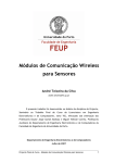
2.2.
Track-changeable Quadruped Walking Robot "TITAN X"[11]
Roller-Walker is a walking machine with a special foot mechanism on each
leg which changes to a sole in leg form and a passive wheel in skating form.
6
Effectiveness of constructing hybrid mobile robot with minimum mechanism and
switching its style of locomotion. On the basis of design method of hybrid mobile
robots that was established in the study on Roller-Walker, hybrid mobile robot had
design and named as "TITAN X" Figure 2.1, which is a quadruped walking machine
that combines the properties of leg and track.
The designed special driving system that combines the functions of tracked
locomotion with those of drive transmission for driving the knee joint. This is belt
driving system that has not only the functions of drive transmission to trim weight of
the end of the leg, but also those of tracked locomotion for moving. TITAN X is
about 900 millimeters long, 600 millimeters wide, 29 kilograms weight. By combine
both, make a good waking ability and tracked locomotion and TITAN X walked on
irregular terrain and made tracked locomotion on regular terrain. In addition, TITAN
X was able to show high-performance motion such as hybrid motion that combines
the properties of leg and track.
(a)
(b)
Figure 2.1: Position Mode: (a) Walking position and (b) Wheel position[11]
7
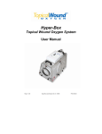
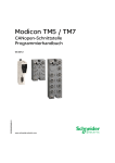
2.3.
Wheel-Leg Hybrid Mobile Robot to Realize a Large Wheel Diameter
Figure 2.2: Wheel-Leg Hybrid Mobile Robot to Realize a Large Wheel Diameter
These journals focus on comparison with the previous wheel-leg module
which divides by three type of wheel - small wheel, large wheel and retractable
wheel. Small wheel face with difficulties of configuration to climb a small singlestep or traverse a single-gap by wheel mode but when it is in walking mode, thanks
to the small footprint, the mobile robot can select the position of the end of the foot
on rough terrain. For large wheel it easy to configuration to climb a small single-step
or traverse a single-gap when it is in wheeled mode[2]. On the other hand, when it is
in walking mode, because of the large footprint, it is difficult for the mobile robot to
select the position of the end of the foot on rough terrain. In addition, the motion
range of the leg is limited. Both types of wheel can take the wheeled mode and
legged mode at the same time but the motion control of the robot becomes quite
complicated especially on rough terrain with a complicated surface structure.
Therefore, retractable wheel is most suitable because it is easy for this type of mobile
configuration to climb the small single-step or traverse the single-gap[2].
8
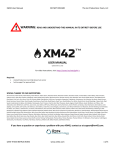
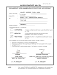
2.4
Roller-Walker
Figure 2.3: Roller-Walker[12]
In the past, active wheels were often used for wheeled robotic system.
However installation of active wheels limited walking machine's ability very much.
Because active wheels need big equipment or machines to operates such as actuators,
brake mechanism and steering mechanism. This equipment is so heavy and massive
which it's not practical solution for walking locomotion which has many degrees of
freedom to generate. "Roller-Walker" is a mobile with a special foot locomotion
mechanism which changes between feet soles for the leg mode and passive wheels
for the wheel mode. Roller-Walker can practical use the installed actuators for
walking, in additional weight become the advantages because is very light. The
wheeled locomotion is based on the same principle of roller-skating. Figure 2.3
shows prototype robot model. The height is 0.25 m; the left/right width is 0.6 m; the
front/back length is 0.5 m; and the total weight is 24 kg. Passive wheels were
equipped on the tips of each TITAN VIII leg and also installed small actuators for
the ankle change. The additional weight is only 7% of TITAN VIII[11]. The camber
angle of passive wheel against the ground is always kept 90deg by parallel link
mechanism using wire and pulley. Both right and left legs are moved symmetrically
to cancel the lateral reaction force. It was demonstrated by experiments that wheeled
locomotion can generate the velocity of 0.8 m/s over twice as large as the walking
speed[12].
9
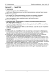
2.5
Autonomous Quadruped Robot
This robot was presented by UTM student for his final year project. This
robot proposed hybrid leg-wheel mechanism and uses 14 servo motors as actuator.12
servo motors was used for the joint and additional two servo motors for wheel mode.
This robot used one analog distance sensor for sensing the obstacles, reacts according
to the situation and has the ability to climb over the obstacle. PIC 18F4550
microcontroller was used as the brain of robot. Acrylic and aluminum plate was used
as the robot chassis and structure due to its light weight, soft but strong material and
solid. The robot has the capabilities to perform optimization of gait patterns on a
legged mode and the implementation of wheel mode on flat surface. This robot has
variety modes of movement such as walking and turning with legged mode,
implementation of wheel mode on flat surface, pass forward obstacles, climbing up
the obstacles, obstacle avoidance and high speed walking mode. All those modes are
activated autonomously by a looping program with mode selection. Figure 2.4 shown
autonomous quadruped robot.
Figure 2.4: Autonomous Quadruped Robot[5]
10
2.6
Forward Movement And Turning
Figure 2.5: Forward Movement And Turning[4]
In this robot, planning is needed to make sure robot can move so by turning
movement in a forward movement of the robot only. Firstly, in forward position is
the right leg, left leg will lift up and move to backward position and centre leg is
lifting the body at left side. Then right leg is moving to backward position which
makes a robot body move to forward at right side. At the same time, left leg move to
forward position but there is no effect to the body because the left body is still in
lifting condition. The details of the robot mechanism are shown in figure 2.5 at no 1
and no 2. After that, at the centre leg the position will be change which make the
robot body is lifting up at right position. Then left leg is lifting up and moving to
backward position which makes a robot body move to forward position at left side.
At the same time, right leg move to forward position but there is no effect to the
body because the right body is still in lifting condition. Combinational of forward
movement of left and right side makes the forward movement of the robot. The
details of robot mechanism are represented in figure 2.5 at no 3 and no 4.
11
CHAPTER 3
3.0 METHODOLOGY
3.1
Introduction
This chapter will discuss the methodology of the project. The methodology
that needed to be taken has been determined to make this project become more
successfully. This chapter will describe the development methodology and guidelines
to build a well quadruped motion robot. In order to meet the objective, three aspects
must be taken into consideration. The first one is the hardware or mechanic structure
of the small-scale. Then the related circuitry for the control system was constructing.
Finally, the control algorithm was developing using the software application.
12
Initial research
Literature review
Project research
Hardware development
Mechanical part
Electronic part
(design body)
(sensor, motor and controller)
Software development
Programming PIC using MATLAB (C language)
Part integration
Integration of mechanical and electronic part
Load program to controller
Testing and fine tuning
Testing prototype & trouble shooting process
Fine tuning and adjustment
Figure 3.1: Flow of Methodology
3.2
Mechanical Part
The prototype of the quadruped motion robot chassis and the locomotion
mechanism of its quadruped leg had been designed and developed. The full design of
the prototype will develop by using aluminum plate and acrylic. For the leg design,
the 2 servo will joint together to make a link and other servo will joint with bracket.
The end of the servo will attach with DC motor and tire. This illustrated as shown in
Figure 3.2.
13
Figure 3.2: Leg Design
14
3.2.1
Mechanical Design
The illustration below summarized the quadruped robot structure and mechanism
design.
Figure 3.3: Leg Mode Design
Figure 3.4: Wheel Mode Design
15
Figure 3.5: Overview: (a) Top view (b) Side view (c) Front view
16
3.3
Hardware Part
Hardware is the mechanical and electronic parts that are put together to build
part of project. It will have to function well and perform according to the determined
function as it will be considered failure if the hardware parts fail to function properly.
Hardware design can be summarized in Figure 3.6. This figure portrays the
connection of the mechanical components and how it’s related to the control system.
As shown in Figure 3.6, 4 servo controller were connected to the PIC18f4520. The
microcontroller will control the speed of the motor by controlling the PWM. Then it
is also shown those IR sensors and analog distance sensor were attached to the
microcontroller. The microcontroller will control the speed of the motor with
comparison between the nominate distance and actual distance then will response by
calculating the desired speed. For servomotor will connect to servo controller, then
servo controller will control by the microcontroller.
Figure 3.6: Map of Hardware Part
17
3.3.1
Microcontroller
A microcontroller is
circuit containing
a
a
small
processor,
computer
memory
on
ROM
a
and
single integrated
RAM,
and
programmable input/output peripherals. Microcontrollers are used in automatically
controlled devices, such as automobile engine control systems, implantable medical
devices, remote controls, office machines, appliances, power tools, toys and
other embedded systems which contact to the microcontroller. Therefore,
PIC18F4250 microcontroller was used in this project because of its low power with
wide operating voltage range; 2.0V to 5.5V, 4x Phase Lock Loop (PLL) – Available
for Crystal and Internal Oscillators with Two External RC modes, up to 4 MHz and
Two External Clock modes, up to 40 MHz, up to 10 MIPS performance, C compiler
optimized RISC architecture and provide 10 bit, up to 13 channels Analog-to-Digital
Converter (A/D) module. The device is manufacturing using Microchip’s highdensity non-volatile memory technology. With high speed FLASH/EEPROM
technology on a monolithic chip, the Microchip PIC18F4250 is a powerful computer
that provides a highly flexible and cost effective solution to many embedded control
applications. Microcontroller will run 56 based on program that user implemented in
this chip. In this project, Microchip PIC18F4250 microcontroller runs at 20 MHz
with 8Kbytes of Flash memory and 256 Bytes EEPROM[8].
Figure 3.7: Microcontroller PIC18F4520[8]
18
3.3.2
Servomotor
Figure 3.8: Servomotor HD-4180BB
A servomechanism or servo is an automatic device which uses error-sensing
feedback to correct the performance of a mechanism. The term correctly applies only
to systems where the feedback or error-correction signals help control mechanical
position or other parameters. Servo motors Figure 3.8 has been used to move the
mechanical part control by electronics circuit.
In this project Digital servos will be used, which have lot significant
operational advantages over standard servos, even coreless versions. Digital servo
differs, is in the way it processes the incoming receiver information, and in turn
controls the initial power to the servomotor, reducing the deadband, increasing the
resolution and generating tremendous holding power. Therefore Servo motors are
very important and useful in robotics.
19
3.3.3
IR Sensor
Figure 3.9: IR Sensor
Infra-red (IR) sensor used the concept of reflection of light to function.
Transmitter transmits the IR packet to an object while receiver receives the packet
sent after the light reflected from the object. Figure 3.9 show the position of both
transmitter and receiver diode and the way of the IR sensor operate. From the figure
detection or reflected packets ranges up to 10 mm from the object. However, the
ranges of transmit and receive depend on type of diode used. In normal condition
where no packets receive, the pin goes high (logic 1) but, after receiving IR packet,
the pins grounded (logic 0). This concept represents the digital logic and easily
adapted for this project. IR sensors used as obstacle detection sensors. It gives ability
to the robot to avoid any potential collision.
20
3.3.4
Servocontroller
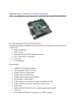
Figure 3.10: Servocontroller SC16A
RC Servo motor controller which a contoller of servomotor. 16 independent
standard RC (Remote Control) is designed to control servo motors simultaneously in
a single board. Each signal pin is able to generate servo pulses from 0.5 ms to 2.5 ms,
which is greater than the range of most servos, further it also can operate 180
degrees. Through UART serial communication, SC16A can be combine in 2 boards
to offer independent control over 32 RC servo motors simultaneously. The controller
of SC16A can either be control by a PC desktop, Laptop with USB port, or
microcontroller with UART communication interface. Both USB and UART
interface present a flexible communication, fast and easy to use in feature. With
USB, user is able to get it running within 5 minutes time. Figure 3 show the servo
controller, SC16A with the connection of servo motors.
21
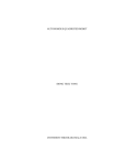
Figure 3.11: : Part of Servocontroller SC16A
Table 1: Label of Function Servocontroller
Label
Function
A
Led as indicator if there any signal transfered or received from
PIC
B
5V,6A to supply the servormotor
C
16 channel pins for servomotors
D
Rx(Receiver), Tx(Transmiter), 5V and GND pins is use to connect
to PIC
E
Indicates if powwer supply from servo and 5V are supplied
The servo controller, SC16A has been designed with capabilities and features of: [9]
•
16 channels: Servo driven independently
•
Extendable to 32 Channels: Two controller linked together to drive 32
servos
•
Optional Position Reporting: User may request position of an individual
servo.
22
•
Optional Servo Ramping: Choose one of 63 ramp rate (speed rate) for
each servo.
•
Sample GUI for computer*: User may control the servo via sample GUI
software.
3.4
•
Resolution: 1.367us.
•
UART: 9600 baud rate
•
Servo pulse: 0.5ms to 2.5ms.
Software And Programming Design
Programming languages can be used to create programs that control the
behavior of a machine and/or to express algorithms precisely. Main is where the
association of movement algorithm and sensor responses takes place. Depending on
sensors response, the main program will decide which movement algorithm will be
selected. The code algorithm must be developed to simply the programming process.
The algorithm is represented by the flow chart in Figure 3.12.
Figure 3.12 show how the program works in the quadruped motion robot.
Firstly, when the switch power suppply is on, the robot will be initialize before mode
selection will make. Initialize means the robot will be at the original position. After
that it will enter to the selection mode. This selection will be set by button. Button 1
will indicate the leg mode, button 2 will indicate the wheel mode and button 3
indicate the obstacle mode.
When Button 1 is been press, robot will starts walking forward and program
will loop for 5 times for walking mode. If Button 2 is been press, robot will starts
move forward by wheel. If Button 3 is been push, robot will starts move forward by
wheel. During its moving by wheel, if sensor 1 or 2 sense any obstacle in front, robot
will stop.
23
When sensor 1 and 2 senses the obstacle, it will rotate to the left by leg mode
in 6 steps after delay in 5 seconds. Then, the robot will move to initial position after
delay in 5 seconds. If there are no obstacles detected, the robot will maintain move to
forward by wheel mode. Those are the flows of programming algorithm and they are
continuously until the main switch is turned off.
Figure 3.12: Flow Chart
24
CHAPTER 4
4.0 EXPERIMENT AND RESULT
4.1
Communication of Servocontroller(SC16A) and PIC18F4520
Microcontroller
Servo controller, SC16A, is one way we can control the position of angle and
speed of servo motors continuously and more accurately. Besides, in this thesis the
servocontroller can control 16 units of servo motors for each servo controller at the
same time. Servo position has their ranges which are between 0-1463. Value of 0
indicates that the position of shaft at position 0 degree and value for 1463 servomotor
will move the shaft to 180 degree. The resolution of SC16A that can be measured is
1.367us. Basically, pulse that generated will start from 0.5ms, so after generating it
will increase the duty cycle by increasing the timing of active pulse according to
value of position. Thus, following formula show the duty cycle of pulses generated:-
Duty cycle
= (Resolution x Servomotor Position/Angle) + 0.5ms .....(1)
= (1.367us x Servomotor Position/Angle) + 0.5ms ..........(2)
Duty cycle increase, the faster servo will rotate to its position but the value of
‘0’ will disable the speed, thus provide normal speed. Servomotor will rotate
according to its own maximum speed. 63 ramp rates allow the user to set the speed of
each servo. Decimal value of ‘1’ will indicate that the servo run at slowest speed and
25
decimal value of ‘63’ will run at the fastest speed. At each 20ms interval, the current
servo position will increase or decrease with the speed value depending on whether
the position is greater or lesser than the new position.
Speed of servomotor is depending on the brand of servo motors because they
have different type of resolution which related to duty cycle. Therefore, different
type of servo would result in different speed because of percent of duty cycle. For
servo HD-4180BB, the approximate time of speed range from 0 degree to 180 degree
of rotation is shown in Table 2.
Table 2: Speed Range from 0 degree to 180 degree of Rotation
Decimal Value
4.2
Speed
(seconds)
0
0.30
1
90.00
10
13.00
20
6.00
30
5.14
40
4.60
50
3.70
60
2.20
63
1.90
Program debugging
After the quadruped motion robot such as hardware, structure, electronic
system and basic robot locomotion program are tested, programming will be the next
stage to enhancement of the robot where more dynamic movement and interesting on
gait pattern. On this stage, creativity and observation of hybrid legged-wheel robot
26
and characteristic play an important role to enhance the quadruped robot movement
and body more flexibility. USB ICSP PIC Programmer offers low cost yet reliable
and user friendly PIC USB programmer solutions to program popular Flash PIC
MCU which includes PIC12F, PIC16F and PIC18F family. For the development of
programmer and debugger, PICkit 2 Development Programmer/Debugger offers a
low-cost development programmer and it is capable of programming on most of the
Microchip’s Flash microcontrollers and serial EEPROM devices. In MPLAB IDE,
PICkit 2 supported device is selected and then from either the Debugger or
Programmer menu to add debugging or programming functions to MPLAB IDE,
respectively. The MPLAB IDE software which is able to support the debugging and
programming process is fully utilized.
Figure 4.1 The MPLAB IDE programming platform.
27
Figure 4.2 PICkit 2 Programmer Applications
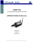
4.3
Mode Selection
Quadruped motion robot consists of 3 mode selection. A push button is
attached and connected to microcontroller as manual modes selection (portD1, D2,
and D3).
28
A
B
C
Figure 4.3 Manual mode selection on robot.
4.3.1
Mode Selection Function
Table 3: Quadruped robot’s mode selection and its function for each mode selected.
Mode selection
A
B
Function
Legged mode including walking gait locomotion, going
forward and backward
Wheel mode including wheel gait locomotion, going
forward and backward
Wheel mode including wheel gait locomotion, obstacles
C
avoidance, turning left and Legged mode including
walking gait locomotion,
29
4.4
Quadruped Robot Formation
The following figure shows the formation of different pattern and gait locomotion.
Figure 4.4: Quadruped Robot Formation
30
4.4.1
Comparison between the design and hardware
(a)
(b)
Figure 4.5 Comparison: (a) Leg mode and (b) Wheel mode
31
4.4.2
Walk forward by leg
Movement is one of the objectives in this thesis, so to make sure it move plan
is need to make sure robot can move in a forward movement of the robot only.
Firstly, robot will initialize on its position of leg mode, both front and back leg are
close together like in wheel mode. Then, left front leg of the robot will lift up and
move forward in about 45 degree. While at same time, left front leg will move to
centre and right back leg move back about 45 degree, this is the way how the robot to
push the body forward. Next, the robot will go back achieve as initial position by lift
up the right back leg and move forward but in the ride side. The robot will repeat the
same movement, lift front leg and move forward. While right front and left back leg
move to push body forward. One sequence of forward movement achieve as the
robot get in intial position back.
(a)
(b)
Figure 4.6: Walk forward by leg :
(a) Left front leg lift up and move forward and (b) Right front leg lift up and move
forward
32
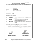
4.4.3
Obstacle Avoidance
Avoid obstacle is most difficult behavior in this part because robot will using
IR sensor as device to detect the object. Firstly, the robot will be in wheel mode, after
the robot detect the object or obstacle in front of the robot it will change to the leg
mode to avoid the obstacle. Then, the robot will turn left by lift up left front leg and
right back leg of the robot about 90 degree. Next, the robot will start to turn by
pushing all 4 leg in 90 degree. After that, the robot will repeat the same step until it
turns left in right position. This is the way how the robot avoid the obstacle by turn
the body to the left.
1
2
4
3
5
6
Figure 4.7: Obstacle Avoidance
33
4.4.4
Electronic part
Voltage Regulator
5V
Microcontroller
Power Supply 5V,
6A
Power Supply
Servomotor
USB ICSP PIC
Programmer
Power Supply 12V,
2A
Voltage Regulator
6V
Figure 4.8: Main Board
Servocontroller
Comparator
(SCA16)
Figure 4.9: IR sensor board and Servocontroller (SCA16)
34
CHAPTER 5
5.0 DISCUSSION AND CONCLUSION
5.1
Discussion
Based on the achievement and respond from the lecturer and student, the
Quadruped Motion Robot project is seen successfully achieve its project scope and
objectives as discussed in chapter one. In the beginning, the robot body was made
from the acrylic. This material is easy to be shape, but due to its softness, the
material cannot handle the total weight of the robot. The use of acrylic has cause the
robot to be unstable especially when the mode changing. Therefore a solution has
been made by using aluminum plate for the body part. The use of aluminum is
proven to be success when it provides more stability for the robot compare to the
previous material. Even though this modification has caused the weight of the robot
to be drastically increased, it does not cause any problem for the robot at all.
Therefore the use of aluminum for body part is perfect for the robot.
For obstacle detection, IR sensors were used on the robot. The IR sensor
install on the robot has been proven to work successfully where it is able to complete
its objective by detecting the obstacle for robot even though the reaction to detect the
obstacle vary long. The microcontroller use for the robot is PIC18F4520 since this
PIC is able to support C programming. The use of PIC18F4520 and C programming
35
has speed up the interface for the robot. The problem encountered in electronic part
of the robot is the low current supply for the servo motor. In the beginning, voltage
regulator 6V was use to supply the current to the circuit and the servo motor. The
voltage regulator is able to supply only 1A current which enough to the circuit,
however the current supply needed for the servo motor is 6A therefore it is
insufficient. Therefore a current booster was made to provide 6A current.
However, the current booster that was made cannot even generate current as
high as 3A. This could be due to the use of unsuitable resistor. In addition to that, the
transistor use for the current booster will overheat whenever the current booster
operates. Therefore another solution was made by switching the battery to a power
supply with supported 5V,6A and 12V,2A which recommended by Cytron.
For the robot communication, the interface between the PIC and the servo
controller is a success. The servo controller is able to operate according to the input
given in the PIC. However the interrupt function was not implemented in the
microcontroller. This has caused an inconvenient in the robot application where
whenever the mode selection button is pushed, it will cause a very long delay in the
system before it obtains the input.
5.2
Suggestion And Future Development
This project has manage to achieve its objective by able to change mode
between the leg mode and the wheel mode. However there are still improvements
that can be done for future development. For future project, more sensors could be
installed to indicate the surrounding environment. After several testing and
demonstration, it is found that the IR sensor that were use does not cover long range
obstacle, therefore more sensor with wider coverage is needed. An example of this
could be ultrasonic sensor.
Another recommendation that can be done is by installing sensor in both leg
and wheel mode. At the moment, the sensor only installed for the wheel mode, which
36
means the obstacle avoidance can only be done during wheel mode. So another set of
sensor should also be installed to leg mode so that the obstacle avoidance system can
be used in either wheel or leg mode. In addition to that, LCD also could be installed
to the robot to indicate which mode it is at the current time.
The final recommendation that can be suggested for future development is by
using more degree of freedom to the robot. By using higher degree of freedom, the
robot movement will be easier and smooth. More movement and orientation can be
applied in the robot to increase its mobility and agility.
5.3
Conclusion
The Quadruped Motion robot platform brings a great significant to the robotic
and artificial intelligent field. The hybrid leg-wheel concept can be widely applied
neither student nor college who do research into it. A variety of dynamic behaviors
were successfully implemented into a hybrid leg-wheel platform. The placement of
wheels at the foot of the legs proved to significantly widen the scope of flexible the
dynamic behavior for a quadruped platform.
Most excited is the ability of robot to avoid obstacles. Based on the
achievement and respond from the lecturer and student, the Quadruped Motion
Robot project is seen successfully achieve its project scope and objectives as
discussed in chapter one. With the strength of 8 servos motor that brings to a flexible
degree of freedom to the robot and 4 servomotors use as wheel it makes the
locomotion and movement of the robot more alive. The inspiration for this robot—
the biological world is filled with examples of legged locomotion. Despite their
limitations legged robots and legged mobile platforms offer a number of advantages
over their wheeled or tracked counterparts; indeed this motivates their continued
study and development. A number of legged systems, humanoid and others have
37
been developed commercially as well as within academia and industrial research
centers.
38
REFERENCES
[1]
Giuseppe Carbone and Marco Ceccarelli (2005), Legged Robotic Systems,
Cutting Edge Robotics ARS Scientific Book, Wien, pp. 553-576, Laboratory
of Robotics and Mechatronics in Cassino, Italy.
[2]
Kenjiro TADAKUMA(Osaka Univ.) and et.al (2010), Mechanical Design of
the Wheel-Leg Hybrid Mobile Robot to Realize a Large Wheel Diameter, The
2010 IEEE/RSJ International Conference on Intelligent Robots and Systems
October 18-22, Taipei, Taiwan
[3]
Shigeo HIROSE, Keisuke KATO (2000), Study on Quadruped Walking
Robot in Tokyo Institute of Technology, Journal - Past, Present and Future Dept.of Mechano-Aerospace Eng., Tokyo Institute off Technology 2-12-1
Oo-okayama Meguro-ku Tokyo 152 Japan
[4]
Tarmizi Bin Ibrahim (2011), Line And Wall Follower Hexapod RoboT,
Master Thesis, Universiti Tun Hussein Onn Malaysia; Batu Pahat Parit Raja.
[5]
Siong Teck Yong (2009), Autonomous quadruped robot, Bachelor Thesis,
Universiti Teknologi Malaysia; Skudai.
[6]
Farizul Bin Mislan (2009), Autonomous Four Wheels Mobile Robot, Bachelor
Thesis, Universiti Teknologi Malaysia; Skudai.
[7]
Ahmad Fakhrurradzy Bin Ramly (2010), Autonomous Four Legged Robot,
Bachelor Thesis, Universiti Teknologi Malaysia; Skudai.
[8]
Michrochip Technology (2008), PIC18F2420/2520/4420/4520 Data Sheet,
Microchip Technology Inc Data Sheet, USA.
[9]
Cytron Technologies (2008), SC16A SERVO CONTROLLER, Cytron
Technologies Sdn Bhd, User’s Manual V1.0, Skudai.
39
[10]
Web Reference. (Hirose Fukushima)
Lab Website, Article,1994, http://www-robot.mes.titech.ac.jp/home_e.html
[11]
Web Reference. (Hirose Fukushima)
Robotic Lab, Track-changeable Quadruped Walking Robot "TITAN X“,
Website, http://wwwrobot.mes.titech.ac.jp/robot/walking/titan10/titan10_e.html
[12]
Web Reference. (Hirose Fukushima)
Hirose Fukushima Robotic Lab, Leg-Wheel Hybrid Walking Vehicle "RollerWalker“, Website,
[13]
Web Reference. (Roller-Walker)
http://www.robot.mes.titech.ac.jp/robot/walking/rollerwalker/rollerwalker_e.
html
[14]
Web Reference. (Wikipedia)
http://en.wikipedia.org/wiki/Microcontroller
[15]
Web Reference. (Michrochip)
http://www.microchip.com/wwwproducts/Devices.aspx?dDocName=en0102
97
40
APPENDIX A
Gant chart
Semester 1, Session 2011/12
Weeks
Project Proposal
Background Study
Search releated
information
Choosing and buy
component
Design mechanism
Build leg mechanism
Build body
Robot Building
Design /build circuit
Report/thesis writing
Presentation
1
2
3
4
5
6
7
8
9
10
11
12
13
14
15
41
Semester 2, Session 2011/12
Weeks
Search releated
information
Robot Building
Design /build circuit
Parts Assembly
Programming
Testing
Modification
Demo Preparation
Report Writing
Presentation
Thesis Compilation
1
2
3
4
5
6
7
8
9
10
11
12
13
14
15
42
APPENDIX B
Source Code
//===========================================================
//
Include
//===========================================================
#include <p18f4520.h>
// this sample code is using
18F4520 !!
#include "delays.h"
#include "usart.h"
//===========================================================
//
Configuration
//===========================================================
#pragma
config OSC = HS
// HS oscillator
#pragma
config FCMEN = OFF
// Fail-Safe Clock
Monitor disabled
#pragma
config IESO = OFF
// Oscillator Switchover
mode disabled
#pragma
config PWRT = OFF
// PWRT disabled
#pragma
config BOREN = OFF
// Brown-out Reset
43
disabled in hardware and
software
#pragma
config WDT = OFF
// WDT disabled (control
is placed on the
SWDTEN bit)
#pragma
config MCLRE = ON
// MCLR pin enabled; RE3 input
pin disabled
#pragma
config PBADEN = OFF
// PORTB<4:0> pins are
configured as digital I/O
on Reset
#pragma
config CCP2MX = PORTC
// CCP2 input/output is
multiplexed with RC1
#pragma
config LVP = OFF
// Single-Supply ICSP
disabled
#pragma
config XINST = OFF
// Extended Instruction
Set
//===========================================================
//
Define
//===========================================================
#define But1
PORTDbits.RD1
#define But2
PORTDbits.RD2
#define But3
PORTDbits.RD3
#define sens1
PORTbits.RD7
#define sens2
PORTDbits.RD6
#define L_Front
0x03
#define L_Back
0x01
#define R_Front
0x04
#define R_Back
0x02
#define L_Front1
0x0D
#define L_Back1
0x0F
44
#define R_Front1
0x09
#define R_Back1
0x07
#define L_TFront
0x0B
#define L_TBack
0x0E
#define R_TFront
0x0A
#define R_TBack
0x08
//===========================================================
//
Global variable
//===========================================================
static volatile unsigned int received_servo_position[0x11];
// Array declared
to store the
feedback position
of servo
//===========================================================
//
Function prototype
//===========================================================
void neutral();
void button(unsigned int mode);
void leg();
void wheel();
void obstacle();
void send_cmd(unsigned int num, unsigned int data, unsigned int ramp);
//UART transmit 4 bytes: servo number, higher byte position, lower byte position
and speed
void delay(unsigned long data);
//delay function, the delay time
void uart_send(unsigned char data);
//===========================================================
45
//
Main function
(main fucntion of the program)
//===========================================================
void main(void)
{
unsigned int j, k, temp;
unsigned char i;
TRISC = 0b11000000;
//set input or output
TRISD = 0b00001110;
//------------------------------------------------------------------------// Configure UART
//------------------------------------------------------------------------OpenUSART( USART_TX_INT_OFF &
// Transmit interrupt off
USART_RX_INT_OFF &
// Receive interrupt off
USART_ASYNCH_MODE &
// Asynchronous mode
USART_EIGHT_BIT &
// 8-bit data
USART_CONT_RX &
// Continuous reception
USART_BRGH_HIGH,
// High baud rate
129);
while(1)
{
neutral();
button (mode);
switch(mode)
{
case 1 :
leg();
break;
46
mode 2 :
wheel();
break;
mode 3 :
obstacle();
break;
}
}
}
CloseUSART();
}//main loop
//========================================================
//
UART subroutine
//========================================================
void send_cmd(unsigned int num, unsigned int data, unsigned int ramp)
{
unsigned char higher_byte=0, lower_byte=0;
if(0x01<=num<=0x16)
{
num=num|0x40;
}
higher_byte=(data>>6)&0x003f;
lower_byte=data&0x003f;
uart_send(num);
uart_send(higher_byte);
47
uart_send(lower_byte);
uart_send(ramp);
}
void delay(unsigned long data)
//delay function, the delay time
{
//depend
on the given value
for( ;data>0;data-=1);
}
//===========================================================
//
Subroutine
//===========================================================
void uart_send(unsigned char data)
{
while(PIR1bits.TXIF==0);
//only send the new data after
TXREG=data;
//the previous data finish sent
}
void neutral();
{
delay(80000);
send_cmd(L_Front1, 603, 0);
delay(5000);
send_cmd(R_Back1, 550, 0);
delay(5000);
send_cmd(R_Front1, 860, 0);
delay(5000);
send_cmd(L_Back1, 950, 0);
delay(5000);
delay(80000);
48
//lurus
send_cmd(L_Front, 461, 0);
delay(5000);
send_cmd(R_Back, 250, 0);
delay(5000);
send_cmd(R_Front, 949, 0);
delay(5000);
send_cmd(L_Back, 1200, 0);
delay(5000);
}
void button(unsigned int mode);
{
unsigned int x;
while(1)
{
if (But1==0)
{return x=1;}
else if (But2==0)
{return x=1;}
else if (But3==0)
{return x=1;}
}
}
void leg();
{
unsigned int i;
delay(80000);
//45
49
send_cmd(L_Front, 1000, 0);
delay(5000);
send_cmd(R_Back, 567, 0);
delay(5000);
send_cmd(R_Front, 400, 0);
delay(5000);
send_cmd(L_Back, 913, 0);
delay(5000);
delay(80000);
for(i=0;i<5;i++)
{
delay(1000);
//45
send_cmd(L_Front1, 328, 0);
delay(80000);
send_cmd(L_Front, 754, 0);
delay(60000);
send_cmd(L_Front1, 603, 0);
delay(5000);
send_cmd(R_Back, 940, 0);
delay(5000);
send_cmd(R_Front, 360, 0);
delay(5000);
send_cmd(L_Back, 913, 0);
delay(5000);
delay(90000);
send_cmd(R_Front1, 1188, 0);
delay(80000);
send_cmd(R_Front, 680, 0);
delay(60000);
50
send_cmd(R_Front1, 860, 0);
delay(5000);
send_cmd(L_Front, 1150, 0);
delay(5000);
send_cmd(R_Back, 567, 0);
delay(5000);
send_cmd(L_Back, 500, 0);
delay(5000);
delay(80000);
}
}
void wheel();
{
unsigned int j;
send_cmd(L_Front, 461, 0);
delay(5000);
send_cmd(R_Back, 250, 0);
delay(5000);
send_cmd(R_Front, 949, 0);
delay(5000);
send_cmd(L_Back, 1200, 0);
delay(5000);
delay(80000);
send_cmd(L_Front1, 603, 0);
delay(5000);
send_cmd(R_Back1, 550, 0);
delay(5000);
send_cmd(R_Front1, 860, 0);
delay(5000);
51
send_cmd(L_Back1, 950, 0);
delay(5000);
delay(80000);
send_cmd(L_Front1, 1126, 0);
delay(5000);
send_cmd(R_Back1, 1144, 0);
delay(5000);
send_cmd(R_Front1, 293, 0);
delay(5000);
send_cmd(L_Back1, 355, 0);
delay(5000);
for(j=0;j<5;j++)
{
delay(80000);
send_cmd(L_TFront, 1000, 0);
delay(5000);
send_cmd(R_TBack, 300, 0);
delay(5000);
send_cmd(R_TFront, 300, 0);
delay(5000);
send_cmd(L_TBack, 1000, 0);
delay(5000);
delay(800000);
}
}
void obstacle();
{
52
unsigned int k;
send_cmd(L_Front, 461, 0);
delay(5000);
send_cmd(R_Back, 250, 0);
delay(5000);
send_cmd(R_Front, 949, 0);
delay(5000);
send_cmd(L_Back, 1200, 0);
delay(5000);
delay(80000);
send_cmd(L_Front1, 603, 0);
delay(5000);
send_cmd(R_Back1, 550, 0);
delay(5000);
send_cmd(R_Front1, 860, 0);
delay(5000);
send_cmd(L_Back1, 950, 0);
delay(5000);
delay(80000);
send_cmd(L_Front1, 1126, 0);
delay(5000);
send_cmd(R_Back1, 1144, 0);
delay(5000);
send_cmd(R_Front1, 293, 0);
delay(5000);
send_cmd(L_Back1, 355, 0);
delay(5000);
do{
53
delay(80000);
send_cmd(L_TFront, 1000, 0);
delay(5000);
send_cmd(R_TBack, 300, 0);
delay(5000);
send_cmd(R_TFront, 300, 0);
delay(5000);
send_cmd(L_TBack, 1000, 0);
delay(5000);
delay(800000);
}while(sen1==1 && sen2==1);
delay(80000);
send_cmd(L_TFront, 0, 0);
delay(5000);
send_cmd(R_TBack, 0, 0);
delay(5000);
send_cmd(R_TFront, 0, 0);
delay(5000);
send_cmd(L_TBack, 0, 0);
delay(5000);
for(j=0;j<10;j++)
{
delay(80000);
send_cmd(L_Front1, 603, 0);
delay(5000);
send_cmd(R_Back1, 550, 0);
54
delay(5000);
send_cmd(R_Front1, 860, 0);
delay(5000);
send_cmd(L_Back1, 950, 0);
delay(5000);
delay(80000);
send_cmd(L_Front, 754, 0);
delay(5000);
send_cmd(R_Back, 567, 0);
delay(5000);
send_cmd(R_Front, 656, 0);
delay(5000);
send_cmd(L_Back, 913, 0);
delay(5000);
delay(80000);
send_cmd(R_Front1, 1188, 0);
delay(80000);
send_cmd(R_Front, 400, 0);
delay(8000);
send_cmd(L_Front1, 603, 0);
delay(5000);
send_cmd(L_Back1, 1206, 0);
delay(80000);
send_cmd(L_Back, 700, 0);
delay(8000);
send_cmd(L_Back1, 950, 0);
delay(5000);
send_cmd(L_Back1, 950, 0);
delay(5000);
send_cmd(L_Front, 461, 0);
55
delay(5000);
send_cmd(R_Back, 250, 0);
delay(5000);
delay(80000);
}
for(k=0;k<10;k++)
{
delay(1000);
//45
send_cmd(L_Front1, 328, 0);
delay(80000);
send_cmd(L_Front, 754, 0);
delay(60000);
send_cmd(L_Front1, 603, 0);
delay(5000);
send_cmd(R_Back, 940, 0);
delay(5000);
send_cmd(R_Front, 360, 0);
delay(5000);
send_cmd(L_Back, 913, 0);
delay(5000);
delay(90000);
send_cmd(R_Front1, 1188, 0);
delay(80000);
send_cmd(R_Front, 680, 0);
delay(60000);
send_cmd(R_Front1, 860, 0);
delay(5000);
send_cmd(L_Front, 1150, 0);
delay(5000);
send_cmd(R_Back, 567, 0);
56
delay(5000);
send_cmd(L_Back, 500, 0);
delay(5000);
delay(80000);
}
send_cmd(L_Front, 461, 0);
delay(5000);
send_cmd(R_Back, 250, 0);
delay(5000);
send_cmd(R_Front, 949, 0);
delay(5000);
send_cmd(L_Back, 1200, 0);
delay(5000);
delay(800000);
send_cmd(L_Front1, 1126, 0);
delay(5000);
send_cmd(R_Back1, 1144, 0);
delay(5000);
send_cmd(R_Front1, 293, 0);
delay(5000);
send_cmd(L_Back1, 355, 0);
delay(5000);
delay(800000);
}