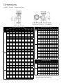
1
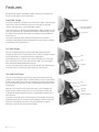
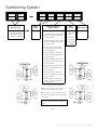
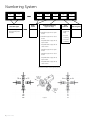
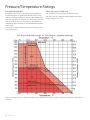
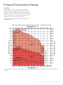
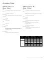
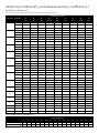
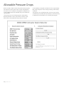
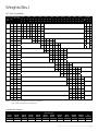
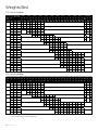
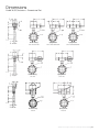
GE Oil & Gas
39003 Series
Technical Specifications
07/2014
Masoneilan* High Performance Butterfly Valves
(HPBV)
2 | GE Oil & Gas
Table of Contents
Foreword.....................................................................................................................3
Rated Flow Coefficients (CV) and Pressure Recovery Coefficients (FL)........12
Features......................................................................................................................4
Standard Valve Components.......................................................................... 14
Numbering System................................................................................................5
Allowable Pressure Drops................................................................................. 16
General Data.............................................................................................................7
Weights.................................................................................................................... 17
Pressure/Temperature Ratings.........................................................................8
Dimensions............................................................................................................. 19
Body Assembly Data.......................................................................................... 10
GE Sales Offices.................................................................................. Back Cover
Actuator Data........................................................................................................ 11
Foreward
GE’s Masoneilan 39003 Series High Performance Butterfly Valve
(HPBV) is a heavy duty automatic throttling control valve that
incorporates the two basic features of the HPBV types. These
features differentiate the the Masoneilan* 39003 Series HPBV
from the conventional swing-through butterfly valve in regards to
sealing method and operational characteristics. Specifically, the
two basic features are: (1) A PTFE, RTFE, or metal seal ring instead
of a liner, and (2) The employment of double offset (eccentric
operation). Each of these features contributes to the improved
performance of HPBV’s compared to conventional butterfly valves.
The use of a seal ring (PTFE, RTFE, or metal) eliminates the inherent
problems of high sealing forces, due to interference fit, and the
resultant high wear rates due to scraping and scuffing of liners.
Also, due to the design of the seal itself, which is a dynamic pressure-assisted member, ANSI Class VI shutoff rates are available
throughout the full range of ANSI Class 150, 300 and 600 ratings
(soft-sealed constructions only).
lash.
PTFE-lined low-friction bearing – Reduces operating torque and
promotes fast response to valve and actuator action. The triple
bearing support of the shaft prevents deflection of the shaft due
to side-loading.
Field replaceable components – Unlike most competitive valves,
shaft and disc need not be purchased as a set. The Masoneilan*
39003 Series Valve uses tapered pins to attach the shaft and disc
positively, yet provide component interchangeability.
Trade names noted throughout are for reference only. GE reserves
the right to supply trade named material or its equivalent.
The double offset (eccentric) operating principles of both seal offset (the seal ring centerline is offset from the shaft centerline – see
Figure 1) and shaft offset (the shaft centerline is offset from the
valve centerline – see Figure 1) allows the disc to get off the seal
quickly due to the camming rotation with respect to the valve/seal
centerlines. This results in minimal sliding (friction producing) contact between the disc and the seal ring with complete separation
after only a few degrees of rotation.
The overall characteristics of the Masoneilan* 39003 Series Valve
are listed below:
• Long seal life – Offset (eccentric) operation gets the disc off the
seal quickly, minimizing sliding contact and friction, resulting
in reduced seal wear and lower breakaway and seating torque
requirements.
• Fast/dynamic operation – Offset (eccentric) operation eliminates disc-to-seal friction throughout the operating range
resulting in fast response to input signals. Also, the disc tends to
move in the direction of flow, assisting the valve and actuator to
maximize the allowable operating pressures.
• Excellent flow characteristics – the offset (eccentric) disc design
provides an approximate equal percentage flow characteristic
through its full travel of 90° rotation yielding a Cv ratio of 100:1.
• Extra heavy shafts with keyed ends for actuator mounting –
precise and accurate positioning without lost motion or back39003 Series High Performance Butterfly Valves (HPBV) | 3
Features
GE’s Masoneilan 39003 Series HPBV includes unique valve seal designs for
metal, soft seal, and fire-safe configurations.
Metal Seal Design
The metal seal design incorporates an Inconel seal for higher tensile strength,
a 300 series stainless steel back-up ring in the seal cavity for axial seal
support, and a disc that is case hardened by nitriding.
The Inconel seal, by its dynamic and flexible design, applies enough force per
linear inch against the disc edge (Rockwell Hardness of C66 to C70) to obtain
an optimum sealing characteristic while controlling the loads between the
metal surfaces.
Disc/Nitrided
300 Series Stainless
Steel Backup Ring
Inconel Seal
The metal seal design can be utilized for temperatures up to 900˚F, in
compliance with ANSI B16.34 pressure/temperature specifications. Leakage
is rated at Class IV per ANSI FCI 70-2.
Soft Seal Design
The soft seal design provides a bi-directional bubble tight shutoff (zero
leakage) through the use of a patented seal. This unique seal design creates a
self-energized seal in vacuum-to-low pressure applications.
Under higher pressure conditions, the seal is also designed to confine and
direct movement of the soft seal against the disc edge, up to the full ANSI
Class 150, 300 and 600 Cold Working Pressures.
The soft seal is designed for high services with minimal wear and low torque.
Seal replacement is a simple procedure requiring no special tools.
Disc
Seal
“O” Ring
Fire-Safe Seal Design
The fire-safe seal design incorporates two patented seals which function
together to seal off pipeline flow. In normal operation, the soft seal provides a
bi-directional “bubble tight” shutoff (zero leakage); the metal seal provides bidirectional shutoff in the event of a fire, in conformance to industry fire-safe
requirements.
With little or no pressure, the fire-safe seal creates a self-energized seal
against the disc. Higher line pressures act on the geometry of both seals
to dynamically load them against the disc, creating higher sealing forces in
either direction.
The metal seal is made of Inconel material which is shaped by a proprietary
hydroforming process into its unique, patented design. Stainless steel outer
bearings are included for post-fire disc and shaft alignment. Fireproof
packing is used to prevent external shaft leakage.
4 | GE Oil & Gas
Disc
Metal Seal
Soft Seal
“O” Ring
Metal Seal Gasket
Numbering System
1st
2nd
3
3
Actuator Type
33Spring Diaphragm
(Air to extend action
only with or without
auxilliary handwheel)
—
—
Body
Series
39
1st
2nd
3
9
3rd
4th
5th
3
Actuator Mounting
(Type 25 Only)
0.Undefined
1. Horizontal above center. Valve
opens on stem extension (airto-open action)
2. Horizontal above center. Valve
closes on stem extension (airto-close action)
Seat
Material
1.PTFE or
RTFE Seal
Ring
Not Assigned
3
2. Inconel
Seal Ring
3. Fire-Safe
Seal Ring
*3. Vertical above center. Valve
opens on stem extension (airto-open action)
*4. Vertical above center. Valve
closes on stem extension (airto-close action)
5. Horizontal below center. Valve
opens on stem extension (airto-open action)
6. Horizontal below center. Valve
closes on stem extension (airto-close action)
7. Vertical above center. Valve
opens on stem extension (airto-open action)
8. Vertical above center. Valve
closes on stem extension (airto-close action)
*Standard Actuator Mounting Arrangement
Note 1: Looking at valve from actuator and
bracket end, valve would not be visible.
Note 2: Positions 1, 2, 5 and 6 shown dotted
and obtained by rotating the valve 180° about
its shaft axis.
Caution: The valve must not be installed
with the actuator mounted vertically below
center.
Figure 2
39003 Series High Performance Butterfly Valves (HPBV) | 5
Numbering System
1st
2nd
3
4
Actuator Type
34 Double acting or
spring return piston
actuator
—
—
Body
Series
39
1st
2nd
3
9
3rd
Actuator Mounting
(Type 25 Only)
0. Undefined
*1. Parallel to pipe. Air to open
action.
*2. Parallel to pipe. Air to close
action.
3. Perpendicular to pipe. Air to
open action.
4. Perpendicular to pipe. Air to
close action.
5. Parallel to pipe. Air to open
action.
6. Parallel to pipe. Air to close
action.
7. Perpendicular to pipe. Air to
open action.
8. Perpendicular to pipe. Air to
close action.
*Standard Actuator Mounting Arrangement
Figure 3
6 | GE Oil & Gas
4th
5th
3
Seat
Material
1.PTFE or
RTFE Seal
Ring
2. Inconel
Seal Ring
3. Fire-Safe
Seal Ring
Not Assigned
3
General Data
Flow Characteristic: equal percentage
Flow Direction: bi-directional
Valve Sizes
ANSI Class
inches
mm
Seal Leakage: per ANSI FCI 70-2 Class VI,
PTFE, RTFE
Class IV, metal seals
150 Carbon
& St. St.
300 Carbon
& St. St.
600(1)
Carbon &
St. St.
2
50
•
•
•
Cv Ratio: 3
80
•
•
•
4
100
•
•
•
6
150
•
•
•
8
200
•
•
•
10
250
•
•
•
12
300
•
•
•
14
350
•
•
•
16
400
•
•
•
18
450
•
•
20
500
•
•
24
600
•
•
30
750
•
•
36
900
•
42
1050
•
48
1200
•
100:1
1. ANSI Class 600 rating available in soft seat constructions only. Consult
GE for fire-safe or metal seat requirements.
39003 Series High Performance Butterfly Valves (HPBV) | 7
Pressure/Temperature Ratings
Soft and Fire-Safe Seal
Steam Service (Soft Seal only)
As temperature increases, the pressure retaining capability of
materials decreases. The graph below illustrates the pressure/
temperature ratings for ANSI Class 150, Class 300 and Class 600.
PTFE sealed valves are rated for 50 psi saturated steam.
Valves with “O” seal configuration (RTFE seal/AFLAS O-ring) are
rated to 100 psi steam service.
The heavy lines define the ratings of the carbon steel and stainless
steel valve body (or “shell”) in conformance to ANSI B16.34. The
shaded areas define the ratings of the PTFE and RTFE Seal materials (Soft Seal).
Seal ratings are based on differential pressure with the disc in the
fully closed position.*
ANSI B16.34 Body and Flowseal Soft Seat Pressure - Temperature Ratings
* Valves with 316SS shafts are rated for maximum pressure differentials of 150 psi for Class 150, 300 psi for Class 300, and 600 psi for
Class 600.
8 | GE Oil & Gas
Pressure/Temperature Ratings
Metal Seal
As temperature increases, the pressure retaining capability of
materials decreases. The graph below illustrates the pressure/
temperature ratings for ANSI Class 150, Class 300 and Class 600.
The heavy lines define the ratings of the carbon steel and stainless
steel valve body (or “shell”) in conformance to ANSI B16.34. The
shaded areas define the ratings of the metal seal.
Seal ratings are based on differential pressure with the disc in the
fully closed position.*
ANSI B16.34 Body and Flowseal Metal Seat Pressure - Temperature Rating
* Valves with 316SS shafts are rated for maximum pressure differentials of 150 psi for Class 150, 300 psi for Class 300, and 600 psi for
Class 600.
39003 Series High Performance Butterfly Valves (HPBV) | 9
Body Assembly Data
Body
Disc
Type:
wafer or lug with integral bonnet
Sizes:
2”, 3”, 4”, 6”, 8”, 10”, 12”, 14”, 16”, 18”, 20”, 24”, 30”, 36”, 42”,
48” (50 mm-1200 mm)
Materials:
carbon steel
ASTM A216 Gr WCB or ASTM A105
stainless steel
ASTM A351 Gr CF8M or ASTM A182-F316
Connections:
flangeless
clamped between ANSI Class 150, 300 or 600 line flanges
single flanged
bolts between ANSI Class 150, 300 or 600 line flanges
Ratings:
ANSI Class 150
carbon steel and stainless steel 2” - 48” sizes (50 mm-
1200 mm)
ANSI Class 300
carbon steel and stainless steel 2” - 30” sizes (50 mm-
750 mm)
ANSI Class 600
carbon steel and stainless steel 2” - 16” sizes (50 mm-
400 mm)
Seal:
PTFE, RTFE or Inconel with 304 stainless steel O-Ring
Type:
offset eccentric disc
Materials:
stainless steel ASTM A351 Gr CF8M or ASTM A182-F316 Nitrided
10 | GE Oil & Gas
Shaft
Type:
Keyed on outboard end
Materials:
17-4 PH stainless steel A564 Gr 630 (others optional)
Valve Bearings:
PTFE-lined fiberglass
bronze (up to 750° F)
stainless steel (above 750° F)
Packing Box:
bolted
Packing
PTFE V-ring
graphite (optional)
Actuator Data
(Model 33) – Sizes 3” – 8”
(80mm – 200mm)
(Model 34) – Sizes 3” – 48”
(80mm – 1200mm)
Type:
Type:
spring-diaphragm, floating stem pneumatic actuator
Action:
Spring-return, or double-acting scotch yoke piston
Body:
increasing air extends stem
Bench Range:
Extruded aluminum, anodized finish sizes 210 to 280 &
88
B size 7-16 psig (48-110 kPa) size 9-16 psig (62-110 kPa)
Ductile Iron sizes 90 and 100
Connection:
Seals:
Buna-N
1/4” NPT
Fail Safe Action:
Pressure rating:
field reversible
Manual Override:
Yoke:
carbon steel
Bracket:
150 psi (1034 kPa) maximum working pressure
cast iron
Declutchable direct mount sizes 210 to 280
Hydraulic size 88
Bevel Gear sizes 90 and 100
Handwheel:
Optional Construction:
(optional) push type tilting, rising stem, permanently
lubricated materials: 17-4 PH and AISI 416 stainless steel
adjustable limit stops
Low temperature or high temperature seals, low
pressure hydraulic.
Bracket Bearing:
a sealed, permanently lubricated ball bearing
Actuator
Size
B
Valve Size
Effective Area
Travel
in.
mm.
sq. in.
sq. cm
in.
mm
3
80
70
452
2.625
66.5
4
100
70
452
2.625
66.5
6
150
140
903
2.625
66.5
8
200
140
903
2.625
66.5
3
80
140
903
2.625
66.5
4
100
140
903
2.625
66.5
optional
C
39003 Series High Performance Butterfly Valves (HPBV) | 11
Rated Flow Coefficients (CV) and Pressure Recovery Coefficients (FL)
Rated Flow Coefficients (CV)
The values shown are for the valve installed in the seal upstream (“SUS”) position.
Degree Open/% Full CV
Valve Size
ANSI Class
2
3
4
6
8
10
12
14
16
18
20
24
30
10°
20°
30°
40°
50°
60°
70°
80°
90°
1.5%
6%
14%
25.2%
38%
55%
75%
97%
100%
150
1.5
6
14
25
39
56
76
99
102
300
1.4
6
13
24
36
52
71
95
100
600
1.4
5
13
23
35
51
70
90
93
150
3.4
14
32
57
87
125
141
221
228
300
3.2
13
30
53
81
117
159
212
223
600
3.1
12
29
52
79
114
156
202
208
150
6.8
27
63
114
171
248
338
437
451
300
6.2
25
58
104
157
228
310
414
435
600
5.8
23
54
98
147
213
290
375
387
150
15.5
66
154
278
419
607
827
1070
1103
300
14.9
60
139
250
377
546
744
992
1041
600
14.7
59
137
247
372
538
734
950
979
150
30.9
124
289
520
784
1135
1584
2002
1064
300
27.3
109
255
459
692
1001
1365
1820
1911
600
26.8
107
250
451
679
983
1341
1734
1788
150
52.8
211
492
886
1336
1934
2638
3411
3817
300
45.6
183
26
767
1156
1673
2282
3042
3194
600
41.2
165
384
692
1044
1511
2060
2665
2747
150
72.6
290
677
1219
1838
2660
3628
4690
4837
300
63.3
253
590
1063
1602
2319
3163
4217
4428
600
58.4
233
545
981
1479
5140
2918
3774
3891
150
90
392
914
1646
2481
3592
4898
6530
6857
300
81
326
760
1368
2063
2986
4072
4530
5702
600
73
292
682
1228
1838
2680
3655
4727
4873
150
132
531
1230
2229
3361
4865
6634
8845
9287
300
109
435
1015
1827
2755
3988
5438
7850
8243
600
96
385
899
1619
2423
3533
4818
6231
6424
150
171
684
1596
3873
4332
6270
8550
11270
11400
300
139
555
1295
2331
3515
5088
6938
9250
9712
150
207
828
1932
3478
3244
7590
10350
13800
14420
300
158
630
1470
2646
3990
5775
7875
10150
10658
150
315
1260
2940
5292
7890
11550
15750
21000
22050
300
242
966
2254
4057
6118
8855
12075
16100
16205
150
491
1965
4585
8253
12445
18012
24563
32750
34388
300
404
1614
3769
6779
10222
14795
20175
26900
28245
36
150
707
2830
6602
1184
17920
25938
35370
45745
47160
42
150
963
3851
8987
16176
24392
35304
48143
62264
64190
48
150
1258
5030
11738
21128
31859
46111
62881
81324
83840
Pressure Recovery Coefficients (FL)
Disc Degree Opening
15
20
25
30
35
40
45
50o
55o
60o
65o
70o
75o
80o
85o
90o
Seal Upstream
.95
.91
.84
.81
.78
.80
.77
.74
.74
.73
.70
.66
.63
.60
.57
.53
Seal Downstream
.94
.89
.84
.82
.80
.77
.75
.72
.69
.66
.63
.30
.58
.55
.54
.53
o
12 | GE Oil & Gas
o
o
o
o
o
o
Standard Valve Components
End Seal Variation
Lower Packing Variation
The ANSI 150 14” through 24” sizes feature a two-piece shaft
design. The lower shaft utilizes an end seal in the body to prevent
external leakage. The component parts include an end seal, an
end cap and end cap bolts.
The ANSI 150 30” through 48”; ANSI 300 14” through 30”; ANSI
600 10” through 16” sizes feature a two-piece shaft design which
utilizes a lower packing seal in the valve body to prevent external
leakage. The component parts are of the same design used in the
packing assembly in the top of the valve body neck.
39003 Series High Performance Butterfly Valves (HPBV) | 13
Standard Materials of Construction
Metal Seal Design
Carbon Steel Construction
Item
Number
Description
-20°F to +450°F
(-29°C to +232°C)
+451°F to +750°F
(+233°C to +399°C)
+751°F to +800°F
(+400°C to +427°C)
2
Shaft
5
Packing
PTFE
17-4 PH Stainless Steel ASTM A564 Gr 630
6
Bearings
Glass-Backed PTFE
10
Body
Carbon Steel A216 Gr WCB or A105
12
Disc
316 Stainless Steel A351 CF8M or A182 F316 Nitrided
14
Seal
Inconel
Graphite
Bronze
316 Stainless Steel Nitrided
Stainless Steel Construction
Item
Number
Description
-100°F to +450°F
(-73°C to +232°C)
2
Shaft
5
Packing
PTFE
Glass-Backed PTFE
+451°F to +750°F
(+233°C to +399°C)
17-4 PH Stainless Steel ASTM A564 Gr 630
+751°F to +900°F
(+400°C to +482°C)
316 Stainless* Steel
ASTM A479 Gr 316
Graphite
6
Bearings
10
Body
316 Stainless Steel A351 CF8M or A182 F316
Bronze
316 Stainless Steel Nitrided
12
Disc
316 Stainless Steel A351 CF8M or A182 F316 Nitride
14
Seal
Inconel
* Metal seal valves with 316 SS shafts have reduced pressure differential ratings. Monel, Nitronic 50 and Inconel (718 or X750) may be
substituted for higher differential pressures and elevated temperatures. Please consult GE for application assistance.
14 | GE Oil & Gas
Standard Materials of Construction
Soft Seal Design
Item
Number
Description
2
Shaft
5
Packing
6
Bearings
-100°F to +400°F
(-73°C to +204°C)
+400°F to +500°F
(+204°C to +260°C)
17-4 PH Stainless Steel ASTM A564 Gr 630
Optional: 316 SS, Inconel 718/750, Monel, Alloy 20, Nitronic 50, Hastelloy C, and Others
TFE
Optional: Graphite
Glass-Backed PTFE
Optional: 316 SS Backed TFE, Hastelloy C Backed TFE
Carbon Steel A216 Gr WCB or A105
10
Body
12
Disc
14
Seal
Optional: 316 SS ASTM A351 CF8M or A182 F316, Monel,
Alloy 20, Aluminum Bronze, or Hastelloy C
316 Stainless Steel A351 CF8M or A182 F316
Optional: Monel, Alloy 20, Aluminum Bronze, or Hastelloy C
PTFE
Optional: RTFE, Polyethylene (UHMWPE)
Fire-Safe Design
Item
Number
Description
-100°F to +400°F
(-73°C to +204°C)
+400°F to +500°F
(+204°C to +260°C)
2
Shaft
5
Packing
Fire-Safe
6
Bearings
Fire-Safe (Garfil & 316 SS)
10
Body
12
Disc
14
Seal
17-4 PH Stainless Steel ASTM A564 Gr 630
Optional: 316 Stainless Steel
Carbon Steel A216 Gr WCB or A105
Optional: 316 SS ASTM A351 CF8M or A182 F316, Monel, Alloy 20, or Hastelloy C, and Others
316 Stainless Steel A351 CF8M or A182 F316 - ENP
Consult Factory for Optional Materials
Fire-Safe (TFE & Inconel)
RTFE & Inconel
Optional: TFE & Monel, TFE & Hastelloy C
RTFE & Monel, RTFE & Hastelloy C
39003 Series High Performance Butterfly Valves (HPBV) | 15
Allowable Pressure Drops
GE has created a simple actuator sizing and selection program,
which allows for quick and accurate actuator sizing based on
the specific service conditions. This program is designed to run
in Microsoft® Excel®, and is available from your local GE sales
representative.
The opening screen of the sizing program is shown below.
Operating variables can be selected from a number of pulldown menus. The program will then provide an actuator
16 | GE Oil & Gas
recommendation, along with calculations for the required torque
(with safety margins) for valve seating, unseating, and throttling
conditions.
This program covers standard product construction only. Please
consult with your local GE sales representative, or with the factory,
for applications and conditions not covered by this program.
Weights (lbs.)
150 Class Assemblies
Actuator Type Valve Brack- RC210
Wt et WT
Valve Type
DA SR
Size
3.1
4
RC220
RC230
DA
SR
DA
4
5.85
8
SR
RC240
DA
SR
RC250
DA
SR
10.4 10.6 15.5 20.4 26.8
RC260
RC270
RC280
DA
SR
DA
SR
DA
27
40
69
69
89
SR
RC88
DA
SR
RCI90
DA
SR
RCG100
33 Actuator
DA
SR Yoke DA
Wt
142 162 330 618 772 684 1102
32
DA
85
2
WAFER
8
12
23.1
24
LUG
11
12
26.1
3
WAFER
11
12
26.1
LUG
13
12
4
WAFER
17
12
LUG
25
2
WAFER
30
12
50
52.4 52.6 57.5 62.4 68.8
69
82
24
139
LUG
35
12
55
57.4 57.6 62.5 67.4 73.8
74
87
24
144
WAFER
44
12
72.5 76.4 82.8
83
96
125 125
24
153
LUG
48
12
75.5 80.4 86.8
87
100 129 129
24
157
10
WAFER
71
14
105.4 111.8 112 125 154 154 174 227
LUG
191
14
125.4 131.8 132 145 174 174 194 247
12
WAFER 110
14
157 170 199 199 219 272
127
14
174 187 216 216 236 289
14
WAFER 135
16
182 195 224 224 244 297
183
16
230 243 272 272 292 345
16
WAFER 182
20
271 271 291 344 364 532
20
339 339 359 412 432 600
6
8
LUG
LUG
LUG
18
WAFER 234
30.4 30.4 35.5
24
64
117
27
2
28.85 31
33.4 33.4 38.5
24
67
120
27
27 28.85 31
33.4 33.4 38.5
24
67
120
28.1
29
29 30.85 33
35.4 35.6 40.5
24
69
122
32.1
33
33 34.85 37
39.4 39.6 44.5
24
73
126
40.1
41
41 42.85 45
47.4 47.6 52.5
24
81
134
20
323 323 343 396 416 584 872 1026 938
305
20
394 394 414 467 487 655 943 1097 1009
WAFER 320
LUG
20
250
24 25.85 28
20
429 482 502 670 958 1112 1024
414
20
523 576 596 764 1052 1206 1118
24
WAFER 505
25
702
25
889 1057 1345 1499 1411 1829
30
WAFER 925
25
1112 1280 1568 1722 1634 2052
1130
25
1317 1485 1773 1927 1839 2257
36
WAFER 1630
25
1985 2273 2427 2339 2757
1890
25
2245 2533 2687 2599 3017
WAFER 2475
LUG
LUG
LUG
LUG
42
25
2830 3118 3272 3184 3602
2700
25
3055 3343 3497 3409 3827
WAFER 2815
25
3170 3458 3612 3524 3942
25
3440 3728 3882 3794 4212
LUG
48
692 860 1148 1302 1214 1632
LUG
3085
NOTES: 1. The weights of actuators are without handwheel
2. DA = Double Acting / SR = Spring Return
Handwheel Weights
Actuator Type
RC210
DA/SR
RC220
DA/SR
RC230
DA/SR
RC240
DA/SR
RC250
DA/SR
RC260
DA/SR
RC270
DA/SR
RC280
DA/SR
RC88
DA/SR
RC90 &
100 DA
RC90 &
100 SR
33
Actuator
1.5
1.5
2.5
2.5
6.5
6.5
26
26
250
185
66
22
39003 Series High Performance Butterfly Valves (HPBV) | 17
Weights (lbs)
300 Class Assemblies
Actuator Type Valve Brack- RC210
Valve Type Wt et WT DA SR
Size
3.1
4
RC220
RC230
DA
SR
DA
4
5.85
8
SR
RC240
DA
SR
RC250
DA
SR
10.4 10.6 15.5 20.4 26.8
RC260
RC270
RC280
DA
SR
DA
SR
DA
27
40
69
69
89
SR
RC88
DA
SR
RCI90
DA
SR
RCG100
33 Actuator
DA
SR Yoke DA
Wt
142 162 330 618 772 684 1102
32
DA
85
2
WAFER
8
12
23.1
24
24 25.85 28
30.4 30.6 35.5
24
64
117
LUG
11
12
26.1
27
27 28.85 31
33.4 33.6 38.5
24
67
120
3
WAFER
11
12
27.1
28
28 29.85 32
34.4 34.6 39.5
24
68
121
LUG
13
12
32.1
33
33 34.85 37
39.4 39.6 44.5
24
73
126
WAFER
17
12
33 34.85 37
39.4 39.6 44.5
24
73
126
LUG
25
2
40 41.85 44
46.4 46.6 51.5
24
80
133
WAFER
30
12
50
52.4 52.6 57.5 62.4 68.8
69
82
24
139
LUG
35
12
69
71.4 71.4 76.5 81.4 87.8
88
101
24
158
WAFER
44
12
79.5 84.4 90.8
91
104 133 133
24
161
LUG
48
12
107.5 112.4 118.8 119 132 161 161
24
189
10
WAFER
71
14
122.4 128.8 129 142 171 171 191 244
LUG
191
14
149.4 155.8 156 169 198 198 218 271
12
WAFER 110
14
194 207 236 236 256 309
14
240 253 282 282 302 355
4
6
8
LUG
14
WAFER 135
LUG
16
328 341 370 370 390 443 463 631
367 380 409 409 429 482 502 370
20
425 425 445 498 518 686 974 1128 1040 1458
20
490 490 510 563 583 751 1039 1193 1105 1523
20
482 482 502 555 575 743 1031 1185 1097 1515
20
606 606 626 679 699 867 1155 1309 1221 1639
WAFER 320
20
619 672 692 860 1148 1302 1214 1632
414
20
844 897 917 1085 1373 1527 1439 1857
WAFER 505
25
847 900 920 1088 1376 1530 1442 1860
702
25
1134 1187 1207 1375 1663 1817 1729 2147
WAFER 925
25
1932 2100 2388 2542 2454 2872
25
2332 2500 2788 2942 2854 3272
LUG
30
16
16
305
LUG
24
250
WAFER 234
LUG
20
183
WAFER 182
LUG
18
127
LUG
1130
600 Class Assemblies
Actuator Type Valve Brack- RC210
Valve Type Wt et WT DA SR
Size
3.1
4
RC220
RC230
DA
SR
DA
4
5.85
8
SR
RC240
DA
SR
RC250
DA
SR
10.4 10.6 15.5 20.4 26.8
RC260
RC270
RC280
DA
SR
DA
SR
DA
27
40
69
69
89
SR
RC88
DA
SR
RCI90
DA
SR
RCG100
33 Actuator
DA
SR Yoke DA
Wt
142 162 330 618 772 684 1102
32
DA
85
2
WAFER
8
12
26.1
27
27 28.85 31
33.4 33.6 38.5
24
67
120
LUG
11
12
28.1
29
29 30.85 33
35.4 35.6 40.5
24
69
122
3
WAFER
11
12
28.1
29
29 30.85 33
35.4 35.6 40.5
24
69
122
LUG
13
12
33.1
34
34 35.85 38
40.4 40.6 45.5
24
74
127
WAFER
17
12
46 47.85 50
52.4 52.6 57.5
24
86
139
LUG
25
2
68 69.85 72
74.4 74.6 79.5
24
108 161
WAFER
30
12
62
94
24
151
LUG
35
12
105 107.4 107.6 112.5 117.4 123.8 1224 137
24
194
WAFER
44
12
99.5 104.4 110.8 111 124 153 153
24
181
LUG
48
12
154.5 159.4 165.8 166 197 208 208
24
236
10
WAFER
71
14
204.4 210.8 211 224 253 253 273 326 346 514 802 956 868 1286
LUG
191
14
267.4 273.8 274 274 316 315 336 389 409 577 865 1019 931 1349
12
WAFER 110
14
286 299 328 328 348 401 421 589 877 1031 943 1361
14
420 433 462 462 482 535 555 723 1011 1165 1077 1495
4
6
8
LUG
16
127
WAFER 182
LUG
250
64.4 64.6 69.5 74.4 80.8
20
1255 1255 1275 1328 1348 1516 1804 1958 1870 2288
20
1255 1255 1275 1328 1348 1516 1804 1958 1870 2288
NOTES: 1. The weights of actuators are without handwheel
2. DA = Double Acting / SR = Spring Return
18 | GE Oil & Gas
81
Dimensions
Model 34 (RC) Actuators - Dimensional Dat
Double Acting
Sizes 210 thru 280
Double Acting
Size 100
Double Acting
Size 88
Spring Return
Sizes 210/230/250/270
Spring Return
Sizes 220/240/260/280
Spring Return
Sizes 100
Spring Return
Sizes 88
39003 Series High Performance Butterfly Valves (HPBV) | 19
20 | GE Oil & Gas
Dimensions
Model 33 Actuator - Dimensional Data
Wafer
Lug
A*
A**
2
3.00
3
Bolt
Circle
Size
H
J
K
L
M
N
P
Q
RC210
1.8
5.7
3.7
11.4
7.1
2.3
2.9
1.3
RC220
5.7
5.7
3.7
11.4
7.1
2.3
2.9
1.3
RC230
2.6
7.7
5.0
13.4
7.9
2.9
4.1
1.9
RC240
7.7
7.7
5.0
13.4
7.9
2.9
4.1
1.9
RC250
3.5
11.2
6.9
19.7 12.6
3.8
5.7
2.7
RC260
11.2 11.2
6.9
19.7 12.6
3.8
5.7
2.7
RC270
5.7
20.1 10.9 31.5 15.7
6.1
8.7
4.3
6.1
8.7
4.3
19.5 39.8
8.7
4.3
B
C
D
E
F
G**
3.00
10.25
1.75
1.06
5/8-11
4
4.75
3.00
3.38
11.00
1.92
1.20
5/8-11
4
6.00
4
3.50
4.13
11.75
2.13
1.26
5/8-11
8
7.50
6
4.88
5.12
13.00
2..31
1.38
5/8-11
8
9.50
Spring Return
Valve
Size
Model 34 (RC) Actuator Table
Thread # of
Size
Holes
8
5.88
6.01
14.13
2.50
1.49
5/8-11
8
11.75
10
6.88
7.88
14.88
2.81
1.70
3/4-10
12
14.25
12
9.50
9.50
16.63
3.23
1.86
3/4-10
12
17.00
RC280
20.5 20.5 10.9 31.5 15.7
14
11.07
11.07
17.25
3.62
2.19
7/8-9
12
18.75
RC88
20.5 37.9 19.5
16
12.05
12.05
22.69
4.00
2.31
7/8-9
16
21.25
18
13.18
13.18
24.00
4.50
2.45
1-8
16
22.75
20
13.94
13.94
25.13
5.00
2.94
1-8
20
25.00
24
16.44
16.44
27.25
6.06
3.12
11/8-8
20
29.50
9.1
RC100
33.5 33.5 19.0 58.0 31.5 10.7 13.8
6.9
RC210
1.8
3.9
3.7
11.4
7.1
2.3
2.9
1.3
RC220
3.9
3.9
3.7
11.4
7.1
2.3
2.9
1.3
2.6
5.3
5.0
13.4
7.9
2.9
4.1
1.9
22.73
22.73
3.62
6.75
3.53
11/8-8
28
36.00
36
32.11
32.11
38.50
8.38
4.34
11/4-8
32
42.75
RC240
5.3
5.3
5.0
13.4
7.9
2.9
4.1
1.9
42
35.62
35.62
44.00
9.25
5.03
11/4-8
36
49.50
RC250
3.5
7.5
6.9
19.7 12.6
3.8
5.7
2.7
48
38.25
38.25
47.25
10.62
5.62
11/4-8
44
56.00
RC260
7.5
7.5
6.9
19.7 12.6
3.8
5.7
2.7
2
3.00
3.00
1025
1.75
1.06
5/8-11
8
5.00
3
3.00
3.38
11.00
1.92
1.20
3/4-10
8
6.63
RC270
5.7
11.8 10.9 31.5 15.7
6.1
8.7
4.3
4
3.50
4.12
11.75
2.13
1.25
3/4-10
8
7.88
RC280
12.2 12.2 10.9 31.5 23.6
6.1
8.7
4.3
6
5.12
5.50
13.00
2.29
1.38
3/4-10
12
10.63
RC88
12.2 29.6 19.5
19.5 39.8
8.7
4.6
8
5.88
7.28
14.14
2.88
1.54
7/8-9
12
13.00
RC100
20.5 20.5 19.0 58.0 31.5 10.7 13.8
6.9
7.38
7.88
15.38
3.25
1.70
1-8
16
15.25
12
10.50
10.50
21.00
3.62
1.86
11/8-8
16
17.75
14
14.57
14.57
22.38
4.62
2.48
11/8-8
20
20.25
16
16.32
16.32
24.00
5.25
2.59
11/4-8
20
22.50
18
17.26
17.26
25.13
5.88
3.03
11/4-8
24
24.75
20
18.49
18.49
26.39
6.31
3.24
11/4-8
24
27.00
9.1
Model 33 Actuator Table
Size
CL 150
10
Double Acting
30
RC230
H
K
L
M
N
P
Q
3
13.00 11.50
J
-
-
-
-
-
-
4
13.00 11.50
-
-
-
-
-
-
6
17.50 15.20
-
-
-
-
-
-
17.50 15.20
-
-
-
-
-
-
11/2-8
24
32.00
8
4.39
13/4-8
28
39.25
3
13.00 11.50
-
-
-
-
-
-
1.20
3/4-10
8
6.63
4
13.00 11.50
-
-
-
-
-
-
1.40
7/8-9
8
8.50
3.06
1.66
1-8
12
11.50
6
17.50 15.20
-
-
-
-
-
-
15.13
4.00
1.85
11/8-8
12
13.75
8
17.50 15.20
-
-
-
-
-
-
13.25
19.00
4.62
2.00
11/4-8
16
17.00
14.67
22.63
5.50
2.53
11/4-8
20
19.25
18.87
30.00
7.00
3.50
11/2-8
20
23.75
24
21.67
21.67
29.38
7.19
30
30.50
30.50
38.88
8.88
3
3.00
3.00
11.00
2.12
4
4.62
4.62
12.00
2.50
6
5.56
6.75
13.62
8
7.38
8.03
10
13.25
12
14.67
16
-
3.62
CL 300
ANSI Class 600
ANSI Class 300
ANSI Class 150
Model 39003 Butterfly Valve Table
* - Dimensions apply to wafer valves only
** - Dimensions apply to lugged valves only
39003 Series High Performance Butterfly Valves (HPBV) | 21
Notes
22 | GE Oil & Gas
Notes
39003 Series High Performance Butterfly Valves (HPBV) | 23
DIRECT SALES OFFICE LOCATIONS
BELGIUM
Phone:+32-2-344-0970
Fax:+32-2-344-1123
KOREA
Phone:+82-2-2274-0748
Fax:+82-2-2274-0794
BRAZIL
Phone:+55-11-2146-3600
Fax:+55-11-2146-3610
MALAYSIA
Phone:+60-3-2161-0322
Fax:+60-3-2163-6312
CHINA
Phone:+86-10-5689-3600
Fax:+86-10-5689-3800
MEXICO
Phone:+52-55-3640-5060
FRANCE
Courbevoie
Phone:+33-1-4904-9000
Fax:+33-1-4904-9010
GERMANY
Ratingen
Phone:+49-2102-108-0
Fax:+49-2102-108-111
INDIA
Mumbai
Phone:+91-22-8354790
Fax:+91-22-8354791
New Delhi
Phone:+91-11-2-6164175
Fax:+91-11-5-1659635
ITALY
Phone:+39-081-7892-111
Fax:+39-081-7892-208
THE NETHERLANDS
Phone:+0031-15-3808666
Fax:+0031-18-1641438
RUSSIA
Veliky Novgorod
Phone:+7-8162-55-7898
Fax:+7-8162-55-7921
Moscow
Phone:
Fax:
+7 495-585-1276
+7 495-585-1279
SAUDI ARABIA
Phone:+966-3-341-0278
Fax:+966-3-341-7624
SINGAPORE
Phone:+65-6861-6100
Fax:+65-6861-7172
SOUTH AFRICA
Phone:+27-11-452-1550
Fax:+27-11-452-6542
SOUTH and CENTRAL
AMERICA and the CARIBBEAN
Phone:+55-12-2134-1201
Fax:+55-12-2134-1238
SPAIN
Phone:+34-93-652-6430
Fax:+34-93-652-6444
UNITED ARAB EMIRATES
Phone:+971-4-8991-777
Fax:+971-4-8991-778
UNITED KINGDOM
Wooburn Green
Phone:+44-1628-536300
Fax:+44-1628-536319
UNITED STATES
Massachusetts
Phone:+1-508-586-4600
Fax:+1-508-427-8971
Corpus Christi, Texas
Phone:+1-361-881-8182
Fax:+1-361-881-8246
Deer Park, Texas
Phone:+1-281-884-1000
Fax:+1-281-884-1010
Houston, Texas
Phone:+1-281-671-1640
Fax:+1-281-671-1735
JAPAN Chiba
Phone:+81-43-297-9222
Fax:+81-43-299-1115
* Trademark of General Electric Company
Other company names and product names used in this document are the registered trademarks
or trademarks of their respective owners.
© 2014 General Electric Company. All rights reserved.
GEA20238A
07/2014