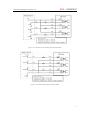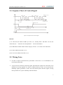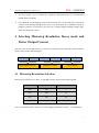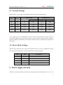
1
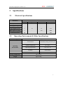
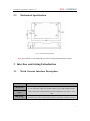
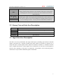
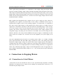
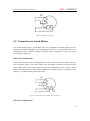
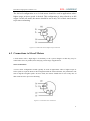
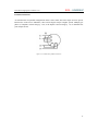
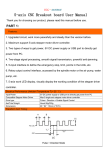
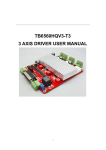
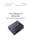
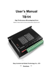
M335 Microstepping Driver Manual V1.0 EMAIL:[email protected] ECG-SAVEBASE WEB: HTTP://STORES.EBAY.CO.UK/SAVEBASE User Manual of M335 High Performance Microstepping Driver M335 Microstepping Driver Manual V1.0 ECG-SAVEBASE ECG Safety Statement Easy Commercial Global is not liable or responsible for any accidents, injuries, equipment damage, property damage, loss of money or loss of time resulting from improper use of electrical or mechanical or software products sold on this website or other Easy Commercial Global sales resources. Since Easy Commercial Global basically provide OEM machine builders components to build their machines for their own use or third party use it is their responsibility to maintain certify and comply the end user products built base on out components sold on this website or other Easy Commercial Global sales resources. Assembling electrical CNC machine component like power supplies, motors, drivers or other electrical components involve dealing with high voltage like AC alternative current or DC direct current which is extremely dangerous and need high attention & essential experience and knowledge of software, electricity, electro-mechanics or mechanics. For technical question please contact us at [email protected] before purchase. 2011 Easy Commercial Global Technology Corporation Limited All Rights Reserved M335 Microstepping Driver Manual V1.0 ECG-SAVEBASE 1 Introduction, Features and Application 1.1 Introduction The M335 is a high performance microstepping driver with low price. The M335 adopts single-chip PWM bipolar sinusoidal chopper to ensure the low vibration and high efficiency. It is suitable for driving 2-phase and 4-phase hybrid stepping motors, so the Nema16-Nema23 stepper motors with a 0.5A-3.5A current will be suitable. If you are looking for a device with low cost, low noise and high-speed, this is an excellent choice for you. 1.2 Features Low cost, Low noise and high-speed. 1, 2, 8, 16 adjustable micro step control for more accurate and smoother motor running. Supply voltage up to 30V DC. Output current up to 3.5A. Single-chip PWM bipolar sinusoidal chopper ensures low vibration and high efficiency Automatic idle-current reduction. Suitable for 2-phase and 4-phase motors. Pulse input frequency up to 400 KHz. Protection of power reversal. High speed optoelectronic isolation signal input. Non-creeping phenomenon under low speed. Low noise and non-resonant region. 1.3 Application Suitable for a variety of small and medium sized automation equipment and instruments, such as: engraving machine, marking machine, cutting machine, laser typesetting, plotters, CNC machine tools, handling the devices. 1 ECG--SAVEBASE M335 Microstepping Driver Manual V1.0 2 Specifications 2.1 Electrical Specifications M335 Parameters Min Typical Max Unit 3A A Output Current 0.6 Supply Voltage +12 +24 +30 VDC Logic Signal Current 7 10 16 mA Pulse Input Frequency 0 - 300 KHZ Isolation Resistance 500 2.2 MΩ Operating Environment & Other Specifications Natural Cooling Cooling Operating Environment Environment Avoid dust, oil fog, corrosive gas Ambient Temperature 0℃-+50℃ Operating Temperature 70℃(158︒F) Humidity 40-90% RH9 Vibration 5.9m/S2 Max Storage Temperature -20℃-125℃ Weight Approx.200g 2 ECG--SAVEBASE M335 Microstepping Driver Manual V1.0 2.3 Mechanical Specification Figure 2.3 Mechanical Specification Note: Recommend use side mounting for better heat dissipation Elimination of Heat 3 Interface and wiring Introduction 3.1 Pin Weak Current Interface Description Function PUL+(+5V) PULDIR(+5V) Details Pulse signal: Single pulse(pulse/direction) mode. 4-5V when PLU-HIGH, 0-0.5V when PUL-LOW. For reliable response, pulse width should be longer than 1.5uS. Series connect resistors for current-limiting when +12V or +24V used. DIR signal: This signal has low/high voltage levels, representing two directions of motor rotation; For reliable motion response, DIR signal should be ahead of 3 ECG--SAVEBASE M335 Microstepping Driver Manual V1.0 PUL signal by 5μs at least. 4-5V when DIR-HIGH, 0-0.5V when DIR-LOW. DIR- Please note that motion direction is also related to motor-driver wiring match. Exchanging the connection of two wires for a coil to the driver will reverse motion direction. EN+(+5V) EN- Enable signal: (NPN control signal, PNP and Differential control signals are on the contrary, namely Low level for enabling.) for enabling the driver and low level for disabling the driver. Usually left UNCONNECTED (ENABLED) 3.2 Strong Current Interface Description Pin Function Details DC+ Power supply, 12~30 VDC. Recommend voltage:24V DCA+, A- Motor Phase A B+, B- Motor Phase B 3.3 Input Interface Description The M335 can accept differential and single-ended inputs (including open-collector and PNP output). The M335 has 3 optically isolated logic inputs which are located on connector P1 to accept line driver control signals. These inputs are isolated to minimize or eliminate electrical noises coupled onto the drive control signals. We recommend to use line driver control signals to increase noise immunity of the driver in interference environments. In the following figures, connections to open-collector and PNP signals are illustrated. 4 M335 Microstepping Driver Manual V1.0 ECG--SAVEBASE Figure 3.3-1 Connections to open-collector signal (common-anode) Figure 3.3-2 Connection to PNP signal (common-cathode) 5 M335 Microstepping Driver Manual V1.0 ECG--SAVEBASE 3.4 Sequence Chart of Control Signal Figure 3.4 Sequence chart of control signals Remark: (1) t1: ENA must be ahead of DIR by at least 5μs. Usually, ENA+ and ENA- are NC (not connected). See “Connector P1 Configurations” for more information. (2) t2: DIR must be ahead of PUL effective edge by at least 5μs to ensure correct direction; (3) t3: Pulse width not less than 1.5μs; (4) t4: Low level width not less than 1.5μs. 3.5 Wiring Notes In order to improve anti-interference performance of the driver, it is recommended to use twisted pair shield cable. To prevent noise incurred in pulse/dir signal, pulse/direction signal wires and motor wires should not be tied up together. It is better to separate them by at least 10 cm, otherwise the disturbing signals generated by motor will easily disturb pulse direction signals, causing motor position error, system instability and other failures. 6 ECG--SAVEBASE M335 Microstepping Driver Manual V1.0 If a power supply serves several drivers, separately connecting the drivers is recommended instead of daisy-chaining. It is prohibited to pull and plug connector P2 while the driver is powered ON, because there is high current flowing through motor coils (even when motor is at standstill). Pulling or plugging connector P2 with power on will cause extremely high back-EMF voltage surge, which may damage the driver. 4 Selecting Microstep Resolution, Decay mode and Driver Output Current This driver uses a 6-bit DIP switch to set micro step resolution, motor operating current and decay mode as shown in the following figure: SW1 SW2 Microstep Resolution SW3 SW4 SW5 Dynamic Current SW6 Decay Mode 4.1 Microstep Resolution Selection Microstep resolution is set by SW1, 2 of the DIP switch as shown in the following table: SW1 SW2 Microstep resolution OFF OFF 1 ON OFF 1/2 ON ON 1/8 OFF ON 1/16 Note: For smooth operation, please try to choose high segmentation, such as 1/16 segmentation 7 ECG--SAVEBASE M335 Microstepping Driver Manual V1.0 4.2 Current Settings Output current is set by SW3, 24of the DIP switch as shown in the following table: SW3 Full Current SW4 Auto Half Current Peak Current RMS Peak Current RMS OFF OFF 3A 2.14A 1.5A 1.07A ON OFF 2.25A 1.6A 0.6A 0.42A OFF ON 1.5A 1.07A 1.5A 1.07A ON ON 0.6A 0.42A 0.6A 0.42A Note: Output current is automatically switched to 50% after signal pulse stop for about 0.4 seconds (according to the table settings). This can make the motor and drive heating reduction, improved reliability. Theoretically 25% reduction in the heat (heat is proportional to the square of the current). 4.3 Decay Mode Settings With the decay mode from 0% to 100%, the attenuation increases. Users can eliminate the stepper motor locked noise and improve motion stabilization by switch SW5, SW6. SW5 SW6 Decay Mode OFF OFF No Decay ON OFF Slow Decay OFF ON Medium Speed Decay ON ON Fast Decay 5 Power supply selection The M335 can match medium and small size stepping motors (from NEMA size 14 to 23) .To 8 M335 Microstepping Driver Manual V1.0 ECG--SAVEBASE achieve good driving performances, it is important to select supply voltage and output current properly. Generally speaking, supply voltage determines the high speed performance of the motor, while output current determines the output torque of the driven motor (particularly at lower speed). Higher supply voltage will allow higher motor speed to be achieved, at the price of more noise and heating. If your speed requirement is low, it is better to use lower supply voltage to decrease noise, heating and improve reliability. Both regulated and unregulated power supplies can be used to supply the driver. However, unregulated power supplies are preferred due to their ability to withstand current surge. If regulated power supplies (such as most switching supplies.) are indeed used, it is important to have large current output rating to avoid problems like current clamp, for example using 4A supply for 3A motor-driver operation. On the other hand, if unregulated supply is used, one may use a power supply of lower current rating than that of motor (typically 50%~70% of motor current). The reason is that the driver draws current from the power supply capacitor of the unregulated supply only during the ON duration of the PWM cycle, but not during the OFF duration. Therefore, the average current withdrawn from power supply is considerably less than motor current. For example, two 3A motors can be well supplied by one power supply of 4A rating. The power MOSFETS inside the M335 can actually operate within +12~30VDC, including power input fluctuation and back EMF voltage generated by motor coils during motor shaft deceleration. Higher supply voltage can increase motor torque at higher speeds, thus helpful for avoiding losing steps. However, higher voltage may cause bigger motor vibration at lower speed, and it may also cause over-voltage protection or even driver damage. Therefore, it is suggested to choose only sufficiently high supply voltage for intended applications, and it is suggested to use power supplies with theoretical output voltage of +12~+ 24V, leaving room for power fluctuation and back-EMF 6 Connections to Stepping Motors 6.1 Connections to 4-lead Motors 4 lead motors are the least flexible but easiest to wire. Speed and torque depends on winding inductance. In setting the driver output current, multiply the specified phase current by 1.4 to determine the peak output current. 9 M335 Microstepping Driver Manual V1.0 ECG--SAVEBASE Figure 6.1 4-lead Motor Connections 6.2 Connections to 6-lead Motors Like 8 lead stepping motors, 6 lead motors have two configurations available for high speed or high torque operation. The higher speed configuration, or half coil, is so described because it uses one half of the motor’s inductor windings. The higher torque configuration, or full coil, uses the full windings of the phases. Half Coil Configurations As previously stated, the half coil configuration uses 50% of the motor phase windings. This gives lower inductance, hence, lower torque output. Like the parallel connection of 8 lead motor, the torque output will be more stable at higher speeds. This configuration is also referred to as half chopper. In setting the driver output current multiply the specified per phase (or unipolar) current rating by 1.4 to determine the peak output current. Figure 6.2-1 6-lead motor half coil (higher speed) connections Full Coil Configurations 10 M335 Microstepping Driver Manual V1.0 ECG--SAVEBASE The full coil configuration on a six lead motor should be used in applications where higher torque at lower speeds is desired. This configuration is also referred to as full copper. In full coil mode, the motors should be run at only 70% of their rated current to prevent overheating. Figure 6.2-2 6-lead motor full coil (higher torque) connections 6.3 Connections to 8-lead Motors 8 lead motors offer a high degree of flexibility to the system designer in that they may be connected in series or parallel, thus satisfying a wide range of applications. Series Connections A series motor configuration would typically be used in applications where a higher torque at lower speeds is required. Because this configuration has the most inductance, the performance will start to degrade at higher speeds. In series mode, the motors should also be run at only 70% of their rated current to prevent overheating. Figure 6.3-1 8-lead motor series connections 11 M335 Microstepping Driver Manual V1.0 ECG--SAVEBASE Parallel Connections An 8 lead motor in a parallel configuration offers a more stable, but lower torque at lower speeds. But because of the lower inductance, there will be higher torque at higher speeds. Multiply per phase (or unipolar) current rating by 1.96, or the bipolar current rating by 1.4, to determine the peak output current. Figure 6.3-2 8-lead motor parallel connections 12 M335 Microstepping Driver Manual V1.0 ECG--SAVEBASE 7 Frequently Asked Questions 13