1
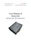
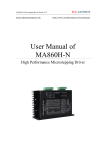
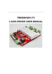
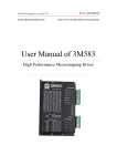
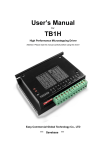
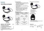
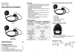
--SAVEBASE
5-axis CNC Breakout board User Manual
Thank you for choosing our product, please read this manual before use.
PART 1:
Features:
1. Upgraded circuit, work more peacefully and steady than the version before.
2. Maximum support 5-axis stepper motor driver controller.
3. Two types of ways to get power, 5V DC power supply or USB port to directly get
power from PC.
4. Two-stage signal processing, smooth signal transmission, powerful anti-jamming.
5. 5-input interface to define the emergency stop, limit, points in the knife, etc.
6. Relay output control interface, accessed by the spindle motor or the air pump, water
pump, etc.
7. 5-axis work LED display, visually display the working condition of the stepper driver
controller.
Electrical Performance (Ambient Temperature Tj = 25 ℃):
Input Power
5V DC power supply or USB port to directly get power from PC
Compatible Stepper Motor Driver
Max 5 single axis stepper motor driver controller
Drive type
Pulse + Direction + Enable Signal Control
Net/Total Weight
About 80g/300g
Dimensions
90 * 82 * 15mm (L*W*H)
Waveform And Timing:
--SAVEBASE
Interface & Pinout Definitions:
--SAVEBASE
Interface Detailed Drawing:
Interface Function & connections:
--SAVEBASE
When testing, check the following notes before use:
1. Check the input voltage of the breakout board (make sure 5V input voltage);
2. Understand how the breakout board works with stepper drivers;
3. Check all the wiring among all the CNC units.
Part 2: The Definition Of Each Pin
1 Defined as parallel control:
PIN9
PIN1
PIN2
PIN14
PIN16
PIN3
PIN7
PIN8
PIN6
PIN5
PIN4
PIN17
Spindle
motor
Enable
X
Pulse
X
Dir
Y
Pulse
Y
Dir
Z
Pulse
Z
Dir
A
Pulse
A
Dir
B
Pulse
B
Dir
2. Hand control is defined as follows 1 ~ PIN15computer-15P interfaces and benchmarks within the
Digital ID)
P1
P2
P3
P4
P5
P6
P7
P8
P9
P10
P11
P12
P13
P14
P15
B
Pulse
B
Dir
A
Dir
Z
Pulse
Y
Pulse
X
Pulse
X
Dir
Enable
5V/V
DD
5V/G
ND
A
Pulse
Z
Dir
Y
Dir
Enable
Enable
3. The limit is defined as 1 to 5
X -Limit
Y- Limit
Z- Limit
A- Limit
Emergency
PLT-P10
PLT-P11
PLT-P12
PLT-P13
PLT-P15
Notes: A. 5V 1A power supply, please take more than switching power supplies, power input
received indicated on the map interface.
B. Spindle motor control is controlled via the parallel port PIN1. Spindle motor voltage must
comply with the supply voltage range.
--SAVEBASE
Part 3: The Use Of Mach3
Figure 1
Figure 1: open the MACH3 software, then select OK now mach3MILL.
Figure 2
MACH3 open the interface shown in Figure 2, the action of commonly used button above, here we
configure the MACH software.
--SAVEBASE
Figure 3
Figure 3: Click the “Config” menu “PORT & PIN” menu.
--SAVEBASE
Figure 4
Figure4: Place on lap 1 setting can set the fundamental frequency, the parameters of the motor
rotation speed. After 2 laps to set the place selected, the configuration pin definitions, as shown in
Figure 5.
Figure 5
According to the definition of the board parallel port, follow the map on the circle to indicate the
definition of modification of the software settings.
--SAVEBASE
Figure 6
Then select the output signals in part, as shown in Figure 6, according to insiders of the settings,
set the corresponding entry.
。
Figure 7
Motor references about the settings in Motor turning and Setup, please set them shown as Figure 7.
Please set each Axis with the above “Neutral values” for test: “320 steps, 600mm/min, 200
mm’s/sec/sec, 2 Step Pulse and 2 Dir Pulse”. Actually, these values can be changed to fit the
motors perfectly after being tested again and again.
--SAVEBASE
Figure 8
Figure 9
Finish all settings, you can click the “Load G Code” menu and run the G code needed, as shown in
Figure 8 and Figure 9.
--SAVEBASE
Figure 10
Having loaded the G code, “RESET” can be seen flashing red, you can use mouse to click the
“RESET” make it stop flashing, then you can press the “CYCLESTART” button to run, detailed
shown in Figure 10.
Contact us:
Web:
E-mail:
http://stores.ebay.co.uk/SAVEBASE
[email protected]