1
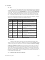
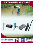
Sassafras River Association
Tidal Monitoring Standard Operating Procedures
1.0
Purpose
The purpose of these procedures is to outline the materials and methods associated with sustaining a high
quality tidal water quality monitoring program in the Sassafras River. These procedures should be used
by the Sassafras RIVERKEEPER® and Sassafras River Association (SRA) support staff to ensure that data
collected is consistent, reliable, and accurate, thus providing considerable benefit for use both within SRA
and across the broader Chesapeake Bay region.
2.0
Definitions
To be added as necessary.
3.0
Responsibilities
The Sassafras RIVERKEEPER® is responsible for organizing and operating the sampling campaign and for
maintaining and enforcing the standards in this document.
4.0
Required Material and Equipment
*denotes equipment required in the field
4.1
Physical Water Parameters
4.1.1
YSI Professional Multi probe instrument*
4.1.1.1 One liter (1 L) brown plastic bottle for on-vessel probe storage*
4.2
4.3
Calibration
4.2.1
pH buffer solutions (3 @ pH – 4.01, 7.00, 10.01)
4.2.2
conductivity calibration solution
Water Clarity
4.3.1
Secchi Disk with marked line*
4.3.2
Water sampler body with marked line and weight (for taking samples at depth) *
4.3.2.1 Seven (7) 60-mL glass sample bottles for bottom turbidity samples*
SRA Tidal Monitoring SOPs
Page 1
4.4
4.5
4.3.3
Seven (7) 250-mL high density polyethylene HDPE bottle for surface turbidity
measurements*
4.3.4
LaMotte 2020e Turbidity Meter
Chlorophyll Supplies
4.4.1
Seven (7) 500-mL polypropylene (PP) sample bottles*
4.4.2
Seven (7) 50-mL syringes*
4.4.3
Seven (7) filter bodies with fourteen (14) filter caps*
4.4.4
Seven (7) 25-mm 0.7-μm porosity GF/F filter membranes*
4.4.5
Opaque Towels*
4.4.6
Aluminum Foil
4.4.7
Filter Forceps
Nutrient Supplies*
4.5.1
4.6
4.7
4.8
Seven (7) 30-mL acid washed polypropylene bottles
Miscellaneous
4.6.1
Kestrel 3500 Pocket Weather Station*
4.6.2
Transport buckets and on-boat cooler*
4.6.3
Camera*
4.6.4
Styrofoam sample transport cooler
4.6.5
Clipboard and Sharpie *
Documents
4.7.1
Vessel Float Plan
4.7.2
Vessel Log
4.7.3
YSI Calibration Sheet
4.7.4
Data Entry Sheets*
Optional Equipment
4.8.1
Personal comfort gear such as sunscreen, hat, jackets, drinking water, etc.
SRA Tidal Monitoring SOPs
Page 2
5.0
Procedures
5.1
Sites
There are seven (7) sites along the tidal reaches of the Sassafras River that are monitored
according to this protocol. Site locations are given below, stored in the SRA database, labeled on
a water-resistant chart located on the RIVERKEEPER® vessel, and stored in the RIVERKEEPER®
vessel’s GPS. The samplers should familiarize themselves with the general location of the sites
prior to departure and then utilize the GPS unit to guide the vessel into close proximity of the
sites. A reasonable effort should be made to sample at the recorded location with a reasonable
tolerance for navigating and anchoring a boat in variable wind and water conditions. Sampling
within 10-15 m of the actual site location can be considered sufficient.
SRA Tidal Monitoring Sites
Site #
Longitude
5.2
Latitude
WK02
39.3674833
-75.8490667
WK03
39.3629667
-75.8909333
WK04
39.3703611
-75.9303333
WK07A
39.3805833
-75.9479500
WK07
39.3796167
-75.9328500
WK08
39.3704000
-75.9849833
WK09
39.3815833
-76.0631833
Description
20m North of Wilson Pt. duck blind.
Just inside western edge of mooring field in
the yacht basin and at the intersection of the
main stem and Dyer Creek.
~10m North of Red Nav. Buoy #10 off of
Big Marsh Pt.
Center of Back Creek just downstream
from intersection with McGill Creek
Center of Foreman Creek at intersection
with Back Creek
Southeast side of channel between Ordinary
Pt. and Kent Co. approximately across from
Green Buoy #3
North of Town of Betterton approximately
at the intersection of the Sassafras River
and Chesapeake Bay
Time Frame
Monitoring of the tidal sites will begin in April and continue through October. Each
season a specific day of the week and time should be developed to provide a consistent sampling
window to incorporate natural fluctuations in environment conditions. For 2010, first sampling
is targeted for Wednesday at 9:30am. Every effort should be made to sample at this day and
time throughout the season, however, should unfavorable weather or other situations arise that
interfere, the collection of data on another day or at another time is preferable to not having the
data for that week. Chlorophyll and nutrient samples are taken on a bi-weekly basis, while other
parameters are sampled weekly. The sites will be sampled in the in the order listed in Section 5.1
to ensure further similar sample timing.
5.3
Preparation in SRA office prior to departure
SRA Tidal Monitoring SOPs
Page 3
5.3.1
Calibrate Dissolved Oxygen, pH, and conductance YSI Professional Plus Multi
Probe instrument according to YSI user manual (Section 9.3)
5.3.1.1 Conductivity and pH standards are located in SRA kitchen as well as
distilled water.
5.3.1.2 Record calibration values on calibration data sheet (Section 9.6) and file
into calibration log located on office bookshelf.
5.3.2
Print weekly data collection sheets for each site (Section 9.7)
5.3.3
Print, complete and post float plan (Section 9.1)
5.3.4
Complete Vessel Log (Section 9.2)
5.3.5
Prepare filters for chlorophyll testing
5.3.5.1 Unscrew each filter holder and using forceps, add a clean 25-mm GF/F
filter with the hatched side facing toward the screen. Screw the two
halves back together and store filter holders in closed filter tube
containers.
5.3.6
5.4
Gather other field supplies specified and indicated under Section 4.0.
General Field Monitoring Method
5.4.1
Proceed to each site, in the order listed in Section 5.1, and anchor the boat within
a reasonable vicinity of the GPS coordinates accounting for how the boat will
rest on anchor given the tidal and wind action.
5.4.2
Record basic site information on the data sheet prior to sampling (e.g. time, date,
weather, tide).
5.4.3
Using handheld Kestrel 3500 weather station take air temperature and wind
speed. Note general weather conditions (sunny, partial sun, cloudy w/ t-storms in
vicinity, etc.). Wind direction can be determined through visual observation of
wave action on water compared to known land orientation or onboard map. Be
advised the GPS unit heading and map orientation are not reliable when the boat
is not moving at a significant speed. Record these in the appropriate location on
weekly data collection sheet (Section 9.7).
5.4.4
The monitoring is easily divided between two people. One person operates the
YSI multi-probe instrument, while the other person collects samples.
5.4.5
The Rule of Three: The rule of three is simply a process that one should use in
the field, in the lab, during clean-up, and when preparing a sample for testing. In
the field, always rinse out the water sampler body as well as the sample bottles
SRA Tidal Monitoring SOPs
Page 4
with water from the site three times before filling the bottle with the sample that
is taken for analysis.
5.5
YSI multi-probe Monitoring
5.5.1
If a site has a depth greater than three meters (3.0 m), measurements will be
taken at one meter (1.0 m) intervals. If a site has a depth of three meters or less
(< 3.0 m), measurements will be taken at half meter intervals. Depth
measurements are obtained from the GPS unit.
5.5.2
Once at the site, lower the YSI multi-probe into the water to the depth of 0.5 m
above the bottom using the marked cable attached to the probe for reference.
5.5.2.1 NOTE: For site WK08 depth (~12.0 -15.0 m) exceeds YSI cable length
(~10 m); therefore, the YSI multi-probe should be lowered to the extent
of available cable without endangering the head computer unit.
5.5.3
Allow the instrument to stabilize and record the values on the screen to the
appropriate row and column on the data sheet: Temperature, Specific
Conductance, Salinity, Dissolved Oxygen (DO) and pH.
5.5.3.1 NOTE: Most parameters will achieve stability rather quickly. DO
however tends to fluctuate to a greater extent. There is no hard or fast
rule as to when it has stabilized to a significant degree as it can be site
and day dependent. Generally record DO once you have confidence that
it seems to be oscillating around a value and not drifting consistently in
one direction.
5.5.4
5.6
Continue raising the cable up every half (0.5 m) or (1.0 m) full meter depending
on procedure outlined in Section 5.5.1, recording values at each interval until
reaching the surface. Always finish with taking a reading at the surface, the
highest level that can be maintain continuous probe immersion given wind and
wave action.
Turbidity Sample Collection
The water sampler body is designed for use in the field and is a simplified water sampler.
The sample is collected in a removable inner bottle which is overflowed 3 times to insure a
representative sample. Samples may be taken at a controlled depth by using a calibrated line.
Attaching a weight to the bottom of the sampling device ensures rapid descent and minimizes the
amount of drift due to currents. More weight should be attached to the sampling device in strong
currents. The sampler body is used to collect one sample one meter from the bottom of each site.
5.6.1
Bottom Turbidity Sample
5.6.1.1 Remove the orange plastic center plug with inlet tubing attached.
SRA Tidal Monitoring SOPs
Page 5
5.6.1.2 Rinse sampler body and 60-mL labeled glass collection bottle with site
water using rule of three.
5.6.1.3 Insert the collecting bottle with the cap removed, into the inner chamber
of the cylinder.
5.6.1.4 Replace the orange plastic center plug and make sure the inlet tubing is
inside the collecting bottle.
5.6.1.5 Attach a weight to the bottom bridle of the sampler.
5.6.1.6 Attach the snap clamp on the calibrated line to the bridle on top of the
sampler.
5.6.1.7 Uncoil enough line to just over the desired depth (intervals are marked as
follows black indicate, 0.25 m intervals, red 1.0 m, and yellow 5.0 m)
5.6.1.8 Quickly lower the water sampler to the desired depth (one meter (1.0 m)
from bottom), cleat on vessel, and leave until full. This usually takes
from 3-5 minutes.
5.6.1.9 Carefully retrieve the water sampler.
5.6.1.10Remove the plastic center plug to expose the collecting bottle in the inner
chamber.
5.6.1.11Remove bottle from the sampler, cap and store the bottle. Dump out the
excess water from the sampler body.
5.6.2
Top Turbidity Sample
5.6.2.1 Rinse 250-mL labeled HDPE using rule of three.
5.6.2.2 Reaching over the gunwale, hold the bottle at 0.5 m beneath the surface
and fill completely (this typically equates to as deep as practical given
the gunwale height of the boat).
5.6.2.3 Cap and store. This sample does not need to be kept cold.
5.7
Nutrient Sample Collection
5.7.1
Take the 30-mL labeled site-specific bottle and rinse using the rule of three.
5.7.2
Reaching over the gunwale, hold the bottle at 0.5 m beneath the surface and fill
completely (this typically equates to as deep as practical given the gunwale
height of the boat).
SRA Tidal Monitoring SOPs
Page 6
5.8
5.9
5.7.3
Place the bottle in a cooler filled with ice on the boat. Samples must be kept cool
and out of sunlight for the duration of field sampling.
5.7.4
Upon return to the office, immediately place samples in refrigerator.
Chlorophyll-a Sample Collection
5.8.1
Rinse the 500-mL labeled site-specific bottle and syringe using the rule of three.
5.8.2
Fill the 500-mL bottle with water just beneath the surface.
5.8.3
Fill the site-specified syringe with well-mixed water from the 500-mL bottle.
5.8.4
Invert (plunger down, opening up) and slowly plunge the syringe, displacing the
water until 50 mL remain in the syringe.
5.8.5
Attach the site-specific, pre-loaded filter holder to the end of the syringe.
5.8.6
Slowly and steadily push the 50 mL of sample water through the filter with the
syringe aligned vertically (filter at the bottom, plunger at top). If the water
becomes very difficult to push through, then stop because the filter is full. Do not
use excess force as this may rupture the filter. Any volume between 30 – 200 mL
of water is acceptable as long as there is some color on the filter. This color
generally indicates a sufficient sample for analysis. Record the volume of water
pushed through the filter on the data collection sheet.
5.8.7
Apply caps to each end of the filter holder and place filter holder in a cooler
filled with ice on the boat. Samples must be kept cool and out of sunlight for the
duration of field sampling.
5.8.8
Cap 500-mL bottle retaining sampled water and store in dark location to bring
back to lab. This sample will serve as a back-up sample should the there be a
filter problem.
Secchi Disk Field Test
A 20-cm Secchi disk, a circular plate-like disk painted in alternating black and white
quadrants is held by a line that is marked in tenths of meters. The Secchi disk is used to give a
measurement of transparency of the water column also called the Secchi depth.
5.9.1
Slowly lower the Secchi disk until it is no longer visible and note the depth using
the markings on the line. Then lower the line slightly deeper.
5.9.2
Slowly raise the Secchi disk until it just becomes visible and note the depth using
the markings on the line.
SRA Tidal Monitoring SOPs
Page 7
5.9.3
Perform steps 1 and 2 three times, noting both readings. Record the mean of the
three readings.
5.9.3.1 NOTE: If the range of measurements for the three sets of readings is
greater than 0.5 m, the entire process should be performed again. Raise
and lower several times around "disappearing" point.
5.9.3.2 NOTE: No sunglasses or any other devices should be used to shade the
eyes while this procedure is being performed.
5.9.3.3 NOTE: The Secchi depth should be determined from the shady side of
the boat during daylight hours.
5.9.3.4 NOTE: The Secchi depths should ideally be determined by the same
person during each sampling session for consistency.
5.10 Turbidity Laboratory Analysis
5.10.1 Remove the Turbidimeter from its case and turn it on.
5.10.2 Calibrate Turbidity Meter (Turbidimeter) according to user manual on seasonal
basis.
5.10.3 Select Measure from the Main Menu of the turbidimeter
5.10.4 Clean off the outside of the turbidity blank bottle using a Kimwipe, insert it in the
turbidimeter, close the lid, and press OK to scan blank as prompted by the
display. Make sure to line up small tab/indent located on the vial and machine.
5.10.5 Shake top or bottom turbidity sample bottle to redistribute solids.
5.10.6
Wash out the glass turbidity sample bottle three times with sample site water and
fill glass sample vial to the indicator line with a well mixed top or bottom
turbidity sample.
5.10.7 Wipe glass sample vial with a Kimwipe, insert the vial in the turbidimeter
(aligning tab/indent), close the lid, and press OK to scan sample. The
turbidimeter will average several readings before recording the final turbidity
reading on the weekly data collection sheet.
5.10.8 Empty glass turbidimeter sample vial and repeat step 5.10.4 through 5.10.7 for
each sample.
5.10.9 Empty all sample bottles and turbidimeter sample vial of site water, rinse with
tap water and allow to air dry.
5.11 Chlorophyll-a Laboratory Processing
SRA Tidal Monitoring SOPs
Page 8
5.11.1 Prepare seven (7) pieces of aluminum foil of approximately roll width and 10 cm
long and fold in half over long axis.
5.11.2 Fold in half again, then unfold, creating a crease.
5.11.3 Create labels using labeling tape noting site #, date, and volume pressed through
filter.
5.11.4 Unscrew filter housing and carefully remove filter using filter forceps
5.11.5 Place filter in aluminum foil with the center of the filter centered on the crease,
with side containing the intercept chlorophyll up (should have slight color to it).
5.11.6 Folding foil and gently assisting with forceps if necessary by pressing on filter
fold the filter in half.
5.11.7 Double over edges of fold, displacing air and create a little pocket in which the
folded filter is located.
5.11.8 Repeat for all samples.
5.11.9 Label foil packets using labels created in Section 5.11.3.
5.11.10 Place foil packets in locking plastic bag and then double bag with another
locking plastic bag.
5.11.11 Place in freezer to await shipment to University of Maryland Center for
Environmental Science Horne Point Lab.
5.11.12 Rinse all filter holders and 500-mL bottles with tap water and allow to air dry.
5.12 Nutrient Sample Laboratory Processing
5.12.1 Store 30-mL labeled sample bottles containing water for Nutrient (Total
Nitrogen/Total Phosphorus) testing in refrigerator until mailed to University of
Maryland Center for Environmental Science Horne Point Lab.
5.12.2 Bag samples with a locking plastic bag to maintain grouping related to sample
date.
5.13 Sample Transportation/Shipping
5.13.1 Nutrient and Chlorophyll samples are analyzed by University of Maryland Center
for Environmental Science Horne Point Lab.
5.13.2 Nutrient Samples
5.13.2.1Samples should be packed with an ice pack(s) in the portable Styrofoam
transport coolers with surrounding cardboard box located in the office.
SRA Tidal Monitoring SOPs
Page 9
5.13.2.2Samples should be mailed overnight to arrive at the following address
Monday-Thursday. The chain of custody form should be included. The
package should also be marked to indicate “nutrient water samples” as
contents.
ATTN: Lois Lane
Analytical Laboratory
University of MD Center for Environmental Science
Horn Point Laboratory
P.O. Box 775
Cambridge, MD 21613
.
5.13.3 Chlorophyll Samples
5.13.3.1It is critical that the chlorophyll samples & foil remain dry. The samples
in foil should, therefore, be double bagged.
5.13.3.2Samples should be packed with dry ice in the portable Styrofoam
transport coolers with surrounding cardboard box located in the office.
5.13.3.3Samples should be mailed overnight to arrive at the following address
Monday-Thursday. The chain of custody form should be included. The
package should also be marked to indicate “chlorophyll samples” as
contents.
ATTN: Crystal Thomas
Analytical Laboratory
University of MD Center for Environmental Science
Horn Point Laboratory
P.O. Box 775
Cambridge, MD 21613
6.0
Safety and Environmental Information
Safety of SRA staff and volunteers is of the upmost importance to the Sassafras River Association
and should be considered the first priority in all situations. Given the inherent variability of working
outdoors in natural environments and equipment and chemicals in a laboratory setting, considerable
hazards exist and care should be taken to minimize risks. These procedures and guidelines are designed to
minimize safety concerns related to known risks, but should not be considered comprehensive or a
substitute for critical analysis and common sense.
6.1
Vessel Operation
The RIVERKEEPER® should always check the weather before heading out on the water. A
trip should be avoided if there is a small craft advisory or a hazardous weather warning
SRA Tidal Monitoring SOPs
Page 10
(thunderstorms, high winds/waves, etc.). It is also recommended that more than one person be on
the boat sampling in case of an emergency. If inclement weather conditions should arise, the
sampling site may become a hazard due to high wind or waves that can be dangerous to the
individuals sampling. If at any time the RIVERKEEPER® and/or support staff feel that unsafe
conditions exist, they are advised to terminate that activity immediately.
Prior to sampling, the RIVERKEEPER® is to file a Float Plan (Section 9.1) giving trip details
such as passengers onboard, destinations, and estimated return time. The RIVERKEEPER® should
also notify a SRA staff member of his/her departure and estimated return time if possible. The Float
Plan should be hung in a conspicuous location in the SRA office.
6.2
Laboratory
The calibration of the instruments requires the use of certain chemicals and standards. While
most of these present no serious threat via accidental contact or spillage, consult the MSDS or
Poison Control (800) 222-1222 in case of emergency. Proper lab safety equipment such as eye
protection and gloves should be worn at all times.
Dry ice can cause frostbite like burns, use gloves or thongs when handling. The sublimation of
dry ice into gas can present a potential explosion hazard in an enclosed environment. Please ensure
adequate ventilation so that pressure build-up does not rupture the packaging.
7.0
Revision History
Date
06/10/2010
06/28/2010
07/09/2010
8.0
Revision
document created
updated shipping procedure to include separate packing methods (dry ice versus
regular ice) for nutrient and chlorophyll
updated with Ted and Janet’s comments and safety information about dry ice
Contacts
8.1
Horn Point Laboratory
8.1.1
Mailing Address
Analytical Laboratory
University of MD Center for Environmental Science
Horn Point Laboratory
P.O. Box 775
Cambridge, MD 21613
SRA Tidal Monitoring SOPs
Page 11
8.1.2
Nutrient Lab
Lois Lane - [email protected] 410/221-8252
Jen O’Keefe – [email protected] 410/221-8276
8.1.3
Chlorophyll/Pigment Lab
Crystal Thomas – [email protected] 410/221-8291
9.0
Appended Documents
9.1
Float Plan
9.2
Vessel Log
9.3
YSI Professional Plus User Manual
9.4
Kestrel 3500 Weather Meter User Manual
9.5
LaMotte 2020e Turbidimeter User Manual
9.6
Calibration Data Sheet
9.7
Data Collection Sheet
9.8
Site Map
9.9
Chain of Custody Form
SRA Tidal Monitoring SOPs
Page 12