1
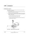
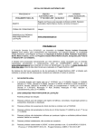
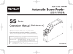
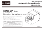
Valco Instruments Co. Inc.
Multiposition
Electric Actuator
Instruction Manual
GENERAL DESCRIPTION ................................................................................... 1
MANUAL USE OF THE MULTIPOSITION VALVE ACTUATOR ............................ 2
CONTROLLING THE ACTUATOR WITH A COMPUTER ....................................... 3
STEP and HOME Commands
Random Access with BCD Logic
ACTUATOR MODIFICATIONS .............................................................................. 7
Changing the Number of Positions (Indexing Angle)
Reversing the Direction of Rotation
VALVE ALIGNMENT .......................................................................................... 12
Causes of Misalignment
Chromatographic Symptoms of Misalignment
Alignment Procedure
TECHNICAL DRAWINGS .................................................................................... 17
WARRANTY ........................................................................................................ 30
MNL-MEA
©2000 Rev. 1/06
Printed in USA
Valco Instruments Co. Inc.
VICI AG International
800 · 367 · 8424 sales
713 · 688 · 9345 tech
713 · 688 · 8106 fax
[email protected]
Schenkon, Switzerland
Int + 41 · 41 · 925 · 6200
Int + 41 · 41 · 925 · 6201
[email protected]
phone
fax
This page intentionally left blank, for printing purposes
General Description
Valco multiposition valves are used to select a flow from a number of
different streams in gas and liquid chromatography and in process stream
applications. Switching them to the desired position can be done manually,
but is best done automatically with either a Valco multiposition air actuator
or the random access Valco multiposition electric actuator described in this
manual. For most laboratory uses, especially where a laboratory computer
is available for control but compressed air is not, the Valco multiposition
electric actuator is the best choice for switching multiposition valves.
The Valco multiposition electric actuator is designed around a highlyintegrated microcontroller, and is capable of detecting the number of valve
positions for which it is configured as well as a number of faults. Actuators
are available in 110 VAC or 220 VAC models for any 4, 6, 8, 10, 12, or 16
position Valco multiposition valve. The model numbers of the actuators are
respectively E4, E6, E8, E10, E12, and E16. (Or E4-220, etc.) An electric
actuator can replace an existing air actuator, and is compatible with most
Valco close mount and standoff assembly hardware.
The actuator consists of (a) the actuator itself, (b) a control box with LED
display, and (c) a 20 conductor interface cable. An actuator typically takes
four seconds to complete 360°; that is, a 4 position valve takes one second
to move the 90° from Position 1 to Position 2.
A computer or data system with external event capacity can be used to
control the actuator using the supplied interface cable. In such a quickly
developing field it would be futile to try to give specifics for each possible
application, but the chapter entitled “Controlling the Actuator with a Computer”
on page 3 provides some general instructions which will be sufficient for
most situations. Consult the factory if additional help is needed.
Manual Use of the Multiposition Valve Actuator
1. Plug the electric actuator into a power outlet (110 VAC or 220 VAC,
50/60Hz, as required). The LED indicator light in the control box (Figure 1)
will light up and indicate the position of the valve/actuator.
2. Press the control box toggle switch momentarily toward HOME. If the
valve is in any position other than Position 1, it will go to HOME (Position 1).
If the valve is in Position 1, it will not move.
As the valve moves toward HOME it sequences through each position,
allowing the possibility that sample may flow briefly as each position
is made. Care must be taken to prevent possible sample loss or
contamination.
3. Move the toggle switch momentarily toward STEP and the valve will
advance from Position 1 to Position 2. If the switch is moved toward
STEP again, the valve will move from Position 2 to Position 3.
������
������
������������
��������������������
�����
������
��������������������������
������
��
��
����
���������
�������
�����
������
����������������
�������
����������
��������
���
���������������
��������
����������
���������������
��������������
����������
�����
��
����
������
����
��
��
���
��
Controlling the Actuator with a Computer
The first step in interfacing the Valco multiposition electric actuator to a
computer or data system is to consult the user’s manual of the control
device to determine what kind of outputs are available, and how many
there are. There may be relays, open collector transistors, logic level
signal outputs, or an RS-232 connector. (These are not cleanly delineated
categories; for instance, BCD logic will involve one of the others.)
The second step is to determine how the valve is to be moved. The
simplest implementation is for the control device to duplicate the STEP
and HOME commands of the manual controller. The other option is to
access the positions randomly via BCD-encoded logic level signals. In
this mode, the actuator passes through each intermediate position, stopping
when it reaches the encoded position. In either case, as the valve sequences
through each position it is possible that sample may flow briefly as each
position is made.
STEP and HOME Commands
Look at Drawing 21464, page 18, to determine the functions of the different
wires in the interface cable. All of the inputs are held at five volts, called a
“logic high”. When they contact ground, the voltage drop signals the logic
circuits in the actuator to direct the motor to the appropriate point.
Locate the violet wire for HOME, the grey wire for STEP, and the white wire
for GROUND. After stripping a small amount of insulation from each of the
wires, touch the grey wire to the white wire and observe that the actuator
advances one position. Touching the violet wire to the white wire causes
the actuator to rotate all the way around to Position 1, or HOME. (If the
actuator is already in Position 1, nothing happens.) The contact must be
maintained for at least 0.2 seconds to be recognized as valid.
These steps demonstrate the goal; that is, getting the control device to
emulate the action of touching the two wires together. Nothing else, such
as applying a voltage to one of the wires, is involved. For relays or open
collector transistors, which are essentially switches, connect the three wires
to the proper terminals as indicated by the manual for the control device.
(Figures 2 and 3)
NOTE: A poor quality relay may cause the unit to step multiple times, due
to the relay’s excessive contact bounce. If contact bounce lasts longer than
50 ms, the actuator will see this as repeated STEP commands.
����
����
����
����
�����
������
����
������
����
����������������������������
�����
�������������������������
����������������������
Controlling the Actuator with a Computer
Random Access
Logic Input
For devices with an RS-232 connector, a simple solution is available in the
form of the Valco Serial Valve Interface (SVI). The SVI is a self-contained
unit, complete with software, that will convert commands from a computer
into positional control for as many as two multiposition and four two position
Valco electric actuators. Designing a similar means of control for a computer
without a serial port requires a little more thought and effort on the part of
the user.
Refer to Drawing 21464 on page 18 to determine the functions of the wires
in the interface cable. All of the inputs are held at five volts, called “logic
high”. When they are pulled to ground potential (“logic low”), the voltage
drop signals the logic circuits in the actuator to direct the motor to the
appropriate point. Randomly accessing the positions involves two steps:
first, a logic low signal must be applied to the proper BCD input lines to tell
the actuator which position to go to; then, a logic low signal must be applied
to the enable line, telling the motor to turn on and find the specified position.
Locate the inputs which are labelled 1’s, 2’s, 4’s, 8’s, and 10’s, plus
PRESET ENABLE and GROUND. Strip a small amount of insulation from
each of these wires. To demonstrate the two steps described in the previous
paragraph, first touch the brown wire (1’s) to the white wire (ground), loading
the code for Position 1. Then, while the brown and white wires are still in
contact, touch the green wire (PRESET ENABLE) to the white wire (ground)
to execute the move to Position 1.
Position 2, 4, 8, and 10 are just as straightforward, but the other positions
involve combinations of two or three wires. To load the code for Position 3,
twist the 1’s and 2’s wires together and touch them to ground. For Position 5,
twist together the 4’s and the 1’s. A complete table appears below.
Position
1
2
3
4
5
6
7
8
9
10
11
12
13
14
15
16
BCD Combination
1’s
2’s
1’s + 2’s
4’s
4’s + 1’s
4’s + 2’s
4’s + 2’s + 1’s
8’s
8’s + 1’s
10’s
10’s + 1’s
10’s + 2’s
10’s + 2’s + 1’s
10’s + 4’s
10’s + 4’s + 1’s
10’s + 4’s + 2’s
Controlling the Actuator with a Computer
����
�����
����
��
�����
��
��
����������
��
��
���
����
�����
����
������������������������������
��������������
To implement the BCD logic, attach the remote cable wires for the PRESET
ENABLE, 1’s, 2’s, etc. to relays or transistor collectors. The white GROUND
wire must go to a “common” point on the control device. (However, direct
connection to open collector transistor outputs may not be suitable in all
environments – the use of opto-isolators may be required. If in doubt,
consult an electronics design expert.) Software must then be created which
will control the appropriate inputs in accordance with the timing diagram
shown in Figure 4. The direct BCD position inputs (DI1- for for BCD1’s
through DI10- for BCD10’s) must be valid before the PRESET ENABLE
pulse (DIPE-) goes low, and should remain valid for the period, td (1.6 milliseconds minimum), after DIPE- goes low. The enabling pulse, DIPE-, should
remain low for the period, tp (5 microseconds minimum). When the STEP
(DIS-) or HOME (DIH-) input is used, it must be held low for the period, ts
(200 milliseconds minimum), to be recognized as valid. (STEP and HOME
operation may be effected with pulses as short as 50 milliseconds, but it is
not guaranteed.)
Logic Output
Some computers have actual BCD logic inputs and outputs, by which the
combinations indicated in the table on the previous page are generated by
the software. This allows a relatively straightforward setup, but matching
the logic sense between the actuator and computer is critical. The input
and output of the actuator are low-true, as supplied from the factory. If the
computer to be used requires a positive true logic (consult the manual for
the computer or interface board being used), the BCD output of the actuator
may be reversed by following these steps to change one of the integrated
circuits:
1. Unplug the actuator. Remove the four 4-40 x 1/4" phillips head screws
which secure the cover to the actuator assembly, and remove the cover
from the body of the actuator assembly.
2. Remove the four 4-40 x 1/4" phillips head screws from the rear cover,
which allows the removal of the PC board inside the cover.
Controlling the Actuator with a Computer
3. Refer to Drawing 22721 on page 19. Replacing integrated circuit U2 (a
4049) with a 4050 changes the output from negative true to positive true.
(Order Valco Product No. I-IC4050.)
4. Reinstall the board in the cover and reassemble the actuator and cover,
making sure that all the wires and cables are reconnected to the Encoder
Board assembly.
When it is certain that the polarities of the actuator and the control device
are compatible, connect the 1’s wire of the actuator interface cable to the 1’s
output, the 2’s wire of the cable to the 2’s output, etc. If the timing restrictions for logic inputs are followed, timing of the logic outputs will also be
in accordance with Figure 4. The signal, RUN, indicating actuation of the
valve, will go high within the period, tr (200 milliseconds maximum), after
DIS- or DIH-. RUN will remain high until the motor stops, and will then go
low. Position data at the outputs, DO1- through DO10- will be valid before
RUN returns low.
Error Signaling
Errors or faults detected by the actuator logic are signalled by the display
flashing in a coded sequence which indicates the problem. The display will
go off briefly once, twice, or three times, followed by a pause before the
cycle repeats.
1: Indicates a fatal internal failure of the microcontroller.
2: BCD position input is invalid; i.e., the position requested cannot be
found on the encoder disk. Clear by entering STEP or HOME, or a
valid position.
3: Indicates motor failure, overheating, or excessive load on the actuator.
Actuator Modifications
Situations occasionally arise when it is desirable to alter an actuator so that
the indexing angle is changed, such as when changing from a 6 position to
an 8 position valve. Or it may be helpful when changing from air to electric
actuation to reverse the rotation so that it will go the same direction as the
air actuator. These modifications can be accomplished by following the
procedures below.
CAUTION: Before performing any operations on the
actuator, make sure the actuator power cord is
unplugged.
Changing the Number of Positions (Indexing Angle)
Tools you will need:
1. 9/64 hex driver
2. 7/64 hex driver
3. #1 or #0 phillips screwdriver
You will also need one of the following, depending on the new valve type:
Product No.
I-21536
I-21537
I-21538
I-21539
I-21540
I-21541
I-21543
I-21542
I-21978
Description
4 position encoder disc
6 position encoder disc
8 position encoder disc
10 position encoder disc
12 position encoder disc
16 position encoder disc
4 x 2 encoder disc (4 column selection)
6 x 2 encoder disc (6 column selection)
10 x 2 encoder disc (10 column selection)
Disassembly
1. Switch the actuator to its HOME position and then unplug the power
cord.
2. Remove the valve and its mounting hardware from the actuator.
For a closemount valve: (Figure 5) Use the 7/64 hex driver to loosen
the socket head screw (6-32 x 5/8") in the CR11 clamp ring between the
valve and the actuator. This allows the valve to be taken off the actuator.
For a valve on a standoff: (Figure 6) Use the 9/64 hex driver to loosen
the socket head screw (8-32 x 5/8" ) in the black-anodized CR3 clamp
ring on the actuator. Pull off the standoff with the valve attached.
3. Remove the four 4-40 x 1/4" phillips head screws which secure the
actuator cover. (One is accessed through the hole in the black rightangle mounting bracket.) Slide the cover back far enough to allow the
power cord and the ribbon cable to be disconnected from the circuit
board. Carefully note how they are attached so that they can be
reconnected later. Now remove the cover completely.
Actuator Modifications
��������
��������
�����������
��������
������
�����������
��������
������
�����
����
����
����������
�����������������������������
�����������������������������
�����
����
���������������������������
�����������������������������
4. Disconnect the motor from the board. (Refer to Drawing No. 22835 on
page 29.)
5. Loosen but do not remove the two 8-32 x 1-1/4" hex head (9/64) screws
which hold the boards to the gearbox. Remove the board/spacer assembly as a unit, lifting it straight up to clear the thin metal encoder disc.
6. Removing the boards exposes the encoder disc, which is the component
that must be changed. Use the 9/64 hex driver to remove the screw and
washer which secure the disc, and then remove the disc, avoiding its
sharp edges. Handle the disc gently so it does not get bent.
Actuator Modifications
Description of the Encoder Discs
������
The encoder disc provides a means
����������
����������
of signalling the position of the
��������������
������
actuator and relaying that information to the logic circuit. If the disc
is thought of as consisting of five
����������
concentric bands, (like an archery ����������
target) the outside band contains
�
���� � �
the “strobe bits.” (See Figure 7)
�
These slots signal the logic circuit to
�������
read the position information and to
��������
stop the motor when the information
����������
conforms to the input command.
The next bands, in order toward the
������������������������������������
center, denote units of one, two,
four, and eight.
In the 4-position disc illustrated in Figure 7, the location that corresponds
to the strobe bit for Position 1 contains only a slot in the “ones” band, so it
registers as “one”. Moving counterclockwise to the next strobe bit, the slot
is in the “twos” band and is read as “two” for Position 2. Since there is no
“threes” band, the information for Position 3 requires a slot which fills the
“ones” band and the “twos” band, registering as 2 + 1, or 3. Position 4 has
simply the one slot in the “fours” band. The 4-position disc affords the clearest
illustration of the principles involved, which are the same all the way up to
the 16-position. To continue the examples, Position 5 has slots in “fours” and
“ones”, Position 9 has slots in “eights” and “ones”, and Position 15 uses the
whole range, 8 + 4 + 2 + 1. The last position location on a 16-position disc
utilizes the last option – no slots at all.
The 4 x 2, 6 x 2, and 10 x 2 are slightly different. The 4 x 2 is essentially an
8-position actuator, but instead of reading out Position 1 through Position 8
it goes from Position 1 to Position 4 and then repeats the succession. Likewise, the 6 x 2 does two sequences of Positions 1 through 6 and the
10 x 2 does two sequences of Positions 1 through 10.
����������
�
����������
�
���� ��
�
����������
����������
�
��
���� ��
�
���� ��
�
����������
����������
����������
��
����������
��
���� ��
�
���� ��
�
�����������
����������
���
����������
�����������
����������
���
����������
����
���� ��
�
���� ��
�
���� ��
�
���� ��
�
�����������
�����
�����
������
�����������������������
10 Actuator Modifications
Reassembly
1. Using Figure 8 and the preceding description, identify the slot on the
replacement encoder disc which determines Position 1. With the motor
toward you and the casting away, install the new encoder disc oriented
as in Figure 8, with the strobe bit of Position 1 vertical. (The part number
should be facing you. In the case of the “x 2’s”, either Position 1 bit may
be vertical.) Be sure to use the correct number of washers between the
disc and shaft, so that the disc is positioned midway between the emitter
and the encoder boards.
2. Position the circuit board assembly and reinstall it with the two 8-32 x 3/4”
screws.
NOTE: If the assembly has come apart, make sure the
spacers are in the proper arrangement: The two shorter
spacers go between the assembly and the gearbox.
Also check at this point to make sure that the disc is not
bent in such a way that it will come into contact with the
board as it revolves.
3. Change the label on the cover to reflect the new number of positions.
Put the cover partially on and reconnect the ribbon and power cables to
the board in the motor assembly. It is necessary that they cross inside
the cover.
4. Hold the ribbon and power cables out of the way against the transformer
as the cover is repositioned over the motor assembly. Put in the four
4/40 x 1/4" phillips head screws which hold the cover in place.
5. Plug in the actuator and step it through all its positions to see that it
works properly.
6. Consult the section entitled “Alignment Procedure” on page 13 for help in
properly installing and aligning the new valve on the actuator.
Consult the factory if additional help is needed.
Reversing the Direction of Rotation
Tools you will need:
1. 9/64 hex driver
2. 7/64 hex driver
3. #1 or #0 phillips screwdriver
Disassembly
Follow the steps for disassembly on page 7. However, before removing
the encoder disc as described in Step 6, use a felt pen to mark the point
on its radius that is at 12 o’clock. If Step 1 was observed and the actuator
was switched to HOME, this will be at the notch (strobe bit) that denotes
Position 1.
Actuator Modifications 11
Reassembly
1 Reinstall the encoder disc with the same point at 12 o’clock but with its
opposite face out. If there is any question about the orientation of the
disc, refer to Figure 8. But remember that once Position 1 has been
located according to that illustration, the disc must be flipped over (on
an axis from 12 o’clock to 6 o’clock, so that the opposite face is out) to
function properly when the direction of the motor is reversed.
2. Locate the three leads (yellow, gray, and black) that form the connection
from the motor to the circuit board. Looking at the connector, observe
the three small metal tines, one for each wire. Depressing the high point
of the tine with a ball point pen or something similar will allow the wire to
be extracted from the connector. See Figure 9. Reverse the positions of
the yellow and gray wires, making sure the wires are pushed back in far
enough to fully engage the tines.
3. Follow the steps for reassembly in the previous section.
������������
��������������
������
����
�����
�������������������������
�����
�����
12
Valve Alignment
When the valve arrives from the factory installed on an actuator, it is
accurately aligned and ready for use. However anytime the clamp ring on
the actuator is loosened, as when removing the valve from the actuator for
mounting through an instrument panel or oven wall, the valve and actuator
must be realigned so that the internal ports and flow passages on the rotor
intersect properly.
CAUTION: Before removing the valve from the actuator,
mark the factory alignment position of the valve.
CLOSEMOUNT: Make temporary registration marks on
the face of the valve where it lines up with the slot in the
stainless clamp ring on the actuator.
STANDOFF: Make temporary registration marks on the
standoff tube where it lines up with the slot in the black
anodized clamp ring on the actuator. Do not remove the
valve from the standoff assembly.
When this mark is lined up with the slot on reassembly,
the factory alignment will be approximately reproduced
as long as the valve and the actuator remain in their
original positions.
Causes of Misalignment
1.Removal of valve from actuator for mounting
As referred to earlier, mounting valves through a bracket or oven wall
requires that the valve or valve/standoff assembly be separated from the
actuator. In the case of a valve on a standoff, this is accomplished by loosening the socket head screw (8-32 x 5/8") in the black anodized CR3 clamp
ring on the actuator, using a 9/64 hex driver. (Figure 6) In valves utilizing
a closemount assembly, the removal is accomplished by using a 7/64 hex
driver to loosen the socket head screw (6-32 x 5/8") in the stainless CR11
clamp ring on the actuator. (Figure 5)
Any time the screw in the CR3 or CR11 clamp ring has been loosened, the
alignment of the valve after replacement on the actuator should be checked.
The chances of proper alignment after reassembly are greatly enhanced by
following the suggestion in the highlighted note found in the box above.
CAUTION: In some applications it is desirable to delete
the black right-angle mounting bracket supplied as part
of the actuator, as when it is replaced by an oven wall or
instrument panel. For the valve mounting and driving
hardware to function properly, the thickness of the substitute must approximate the thickness of the bracket.
Consult the factory if problems are experienced.
Valve Alignment 13
2.Shock from heavy or continuous use
Occasionally, when valves are used in applications requiring a high-duty
cycle, wear or shock can cause the screw and clamp ring to loosen. Instrument vibration may have the same effect. This allows the standoff to move,
causing inaccurate rotor rotation. The most obvious symptom is observable
movement of the standoff, valve, or actuator, which normally do not move
when the valve is actuated.
Chromatographic Symptoms of Misalignment
1.Loss of flow or blocked flow
When the valve body, rotor, and actuator are not in proper alignment, the
ports do not completely intersect the flow passages on the rotor. In the
worst case there is no flow in any position, but slight misalignment may
eliminate flow from ports on one side of the valve only. With a rotometer or
a line placed into liquid, gas flow may be observed between positions as
the actuator cycles the valve. In liquid applications, blocked flow may cause
pump shutdown or failure of other components due to pressure buildup.
2.Mixing of samples
In some configurations with large ports and their corresponding large flow
passages which are very close together, poor alignment can cause mixing
of samples even when a flow restriction has not been observed. This may
be manifested as “ghost” peaks or poor reproducibility.
Alignment Procedure
NOTE: The alignment procedures for air actuated and electrically actuated
valves are not the same. For an air actuated valve, see Technical Note 707,
Operation Notes and Alignment Instructions, Air Actuated Multiposition
Valves.
Description
The valve will have either one (SD and SC types) or two (SF and ST types)
rows of ports evenly spaced around the circumference of the body. See
Figure 10. In addition there will be one (SD and SF types) or two (SC and
ST types) “common” ports offset to either side of these rows. By convention,
Position 1 falls counterclockwise from these common port(s) when the valve
is viewed from the end away from the actuator. The rotor will have either
one or two flow passages appearing as engraved rings around the seal,
which intersect the common port(s). Flow passages perpendicular to the
ring(s) connect the ring(s) to the selected port(s).
STUW
The only configuration which does not fall within this description is
the STUW. Unlike the standard ST, these have one row of ports
around the circumference, with two common ports offset in the
same direction. The common ports are 180° apart, so only one
shows in Figure 10. Special instructions and descriptions regarding
STUW’s will be highlighted in this manner at several points in the
procedures which follow.
14 Valve Alignments
���������������
���������������
���������������
����������
����������
����������
�������������
��������������
�������������
�������������
���������
�������������
���������
�������������
���������
��
�������������
��
�������������
���������������
���������������
����
�������������
���������������
����������
�����������������
�������������
��������������������
��������������������
�������������
��������������
�������������
���������
��
�������������
��
�������������
�������������
���������
�������������
�������������
���� ���������
�������������
���������������������������������������������
���������
Basically, this procedure is a method of centering the perpendicular engraving on the selected port by determining the point at which flow begins (when
the engraving just starts to intersect the port) and the point at which flow
ends (when the engraving ceases to intersect the port), and centering the
rotor between those two points.
1. Plug the actuator in. If the position indicator doesn’t read “1”, flip the
switch to the HOME position.
2. Place the valve or valve and standoff combination on the actuator.
By convention, the factory alignment places the common port(s) at
12 o’clock. Re-orienting the standoff or the slotted coupling (in closemount applications) on the square drive of the actuator allows three
other possibilities.
For a valve on a standoff, make sure the standoff butts all the way
against the actuator so that the drive mechanism is completely engaged.
Tighten the clamp ring screw enough to keep the standoff from falling
out when it is released, but make sure it is loose enough to allow the
assembly to be turned during the alignment procedure.
For a closemount valve, make sure that the ends of the pin in the rotor
are engaged by the slots of the coupling. Tighten the clamp ring screw
enough to keep the valve from falling out when it is released, but make
sure it is loose enough for the valve to be turned during the alignment
procedure.
Valve Alignments 15
3. Establish a flow of clean gas (50 psi is adequate) into the port offset
away from the actuator. This port, called the alignment inlet in Figure 10,
will be the designated inlet throughout this procedure.
STUW
Establish gas flow into the common port at 6 o’clock (alignment inlet
in Figure 10).
4. With the valve facing you and the actuator behind the valve, the port
to the left of or counterclockwise from the alignment inlet corresponds
to Position 1. (See Figure 10. This is the opposite of valves on air
actuators.)
STUW
With the common port at 6 o’clock as the alignment inlet, the port to
the left of or counterclockwise from the common port at 12 o’clock
corresponds to Position 1.
If the gas is flowing from the port in Position 1, go to Step 5. If you hear
no flow, grip the valve and rotate it either way as necessary (the actuator
keeps the rotor fixed) until gas flows from this port.
NOTE: When listening for flow, it is helpful if the fittings are removed from
the port under consideration but left in the adjacent ports. If all the fittings
have been removed, install a loop connecting the two adjacent ports to better isolate the sound of the flow.
5. Grip the valve and rotate it counterclockwise a few degrees past the point
where flow stops.
This sets up a “staging area” for the approach to Position 1.
6. Grip the valve and slowly rotate it clockwise until the first traces of flow
are heard from the port of Position 1. (The port to the left of the alignment
inlet.)
����������
7. While holding the valve
steady, use a soft pencil or
ink marker to make a mark
on the standoff corresponding to the slot in the actuator
clamp ring. This slot makes
a clear fixed reference point
for observing relative rotational positions. In the case
of a closemount valve, make
this mark on the valve body.
(Figure 11)
��������
����������
���������
�����������
��������
������������������������������������
��������������������������
8. Continue the slow manual clockwise rotation of the valve body through
the point of peak flow and beyond until the flow stops or is barely perceptible, as in Step 6.
9. Make another mark as in Step 7. (Figure 11)
10. Make a third pencil mark halfway between the first two and rotate the
valve counterclockwise until this midway mark is reached. (Figure 11)
16 Valve Alignments
11. While holding the valve steady, firmly tighten the screw in the clamp
ring. The rotor should be properly positioned at the point of maximum
flow when the actuator is stepped to the next position.
Congratulations, the procedure is complete. It is a good idea to cycle the
valve through all its positions to be certain everything is functioning properly.
In some cases it is possible to do an additional check by simply looking down
the fitting detail and into the port as the valve is stepped from position to
position. If it is a valve which has a relatively short distance from the bottom
of the detail to the internal taper, the engraved “dimples” on the seal are
visible as they come into alignment with the port.
Consult the factory if additional help is needed.
����
�����
�����
��������
�����������
������
����
�����
�����
����
����
����������������������������
�����������������������������
��������
��������
������
�����
�����
�������������
������
������������������������������
�����������������������������
�����
�����
17
Technical Drawings
Interface Cable Assembly.................................Drawing 21464
Page 18
Logic Board Schematic.....................................Drawing 22721
Page 19
Logic Board Assembly......................................Drawing 22720
Page 20
Controller Assembly..........................................Drawing 21412
Page 21
Encoder Board Schematic................................Drawing 22727
Page 22
Encoder Board Assembly.................................Drawing 22726
Page 23
Driver Board Schematic....................................Drawing 22724
Page 24
Driver Board Assembly.....................................Drawing 22723
Page 25
Transformer Board Assembly...........................Drawing 22729
Page 26
Transformer Board Schematic..........................Drawing 22730
Page 27
Multiposition Electric Actuator Assembly..........Drawing 22835
Page 28
Multiposition Electric Actuator
Motor Assembly................................................Drawing 22834
Page 29
�� ������������������������������������
�� �����������������������������������
������������������������������
�� �����������������������������������
�����
���������
�������������
���
���������
���
���
���
���
����
���
���
���
���
���
����
����
����
������������
���
���
���
���
���
��������
������
������
����
������ ������
�����
���������
�������
��������
������
�����
��������
����
�������
������
����
�����������������
��
�������������������
���������
����
������
����
�����
�
������
��������
���������
�
����
��������������
���
�����
��
�������
�����
�����
�����������
��������������������
���������������������
���������������������������
������������������������������������������������������������������������
��������
������������������������������������������������������������������������
�������
�����������������������������������������������������������������������
�����
����������������������������������
�����
�����
����
������
����
�����
������
������
���
�����
�����
�����
����
������
����
�����
������
������
���
���������
�����������
����������������������������������
�����
�
���
18 Technical Drawings
+5
C5
.10UF
50V
C3
.10UF
50V
S4
S3
S2
S1
HDR2X5
HW-S
HW-S
HW-S
HW-S
J3.10
J3.9
J3.8
J3.7
J3.6
J3.5
J3.4
J3.3
J3.2
J3.1
C6
.10UF
50V
C4
.10UF
50V
+5
+5
S8
9
8
7
6
3
4
5
1N4734
D9
10
TD
ID4
ID2
ID1
BR2
BR1
RS
WDI RS
2
SW1
U4
DS1232
RSI TOL
1
2
7
1
+5
76SB05
MOTOR-
S4
S2
S1
STR
3
C1
27PF
50V
ALE/
PROG
P1.6
R4
620
+5
17 P3.7
15 P3.5
16 P3.6
DIPE* 12 P3.2
RUN 13 P3.3
14 P3.4
D10
LTL223
P2.7
P2.6
P2.5
P2.4
P2.3
P2.2
P2.1
P2.0
P1.7
P1.5
87C51
P1.4
P1.3
P1.2
P1.1
P1.0
P0.7
P0.6
P0.5
P0.4
P0.3
P0.2
P0.1
P0.0
RST/
VPD
10 P3.0
11 P3.1
9
29 /PSEN
30
/EA
18 XTAL2
C2
27PF
50V
31
+5
X1
4.9152MHz
1
2
19 XTAL1
U1
+5
4
5
25
28
27
26
3
24
22
23
2
21
ID2
ID1
S8
S4
S2
S1
STR
7
1
5
1
2
U3
e
d
c
b
a
BL
g
STRB f
A
B
C
D
LT
Q1
MPS-A13
+5
4
5
2
3
3
6
+5
15
14
14
15
9
R3
R2
330
SEG1E
SEG1F
SEG1G
10
9
8
6
7
SEG2C
SEG2B
SEG1D
11
5
RN2
SEG1C
12
3
11
4
SEG1B
13
10
SEG1A
14
2
12
760-3-R330
10
1
HOME-
STEP-
U2
12
9
11
5
6
7
4
2
3
4049
3
5
J2.16
J2.15
J2.14
J2.13
J2.12
J2.11
J2.10
J2.9
J2.8
J2.7
J2.6
J2.5
J2.4
J2.3
J2.2
J2.1
DO10-
DO8-
DO4-
DO2-
DO1-
SE-
RUN
+SE
OUTPUTS
BCD
POSITION IND.
INPUTS
BCD
ADDRESS
BD.# I-22720 Rev. C
J1.20
J1.19
J1.18
J1.17
J1.16
J1.15
J1.14
J1.13
J1.12
J1.11
J1.10
J1.9
J1.5
J1.7
J1.6
J1.8
J1.4
J1.3
J1.2
J1.1
HDR2X10
DATE
7/22/95
11/28/95
03/14/96
INITIATED
J.DURR
J.DURR
J.DURR
22721
FILE NAME
CHECKED
CHRIS
DESIGNED
R.DINNING
DRAWN
APPROVED
\EA\
SUB-DIR
4/22/94
DATE
TOLERANCES UNLESS
63
OTHERWISE SPECIFIED
FRACTIONS
DEC.
ANGLES
.X.1
1/64"
1
.XX.01
.XXX.005
B
SIZE
USA PROJECTION
---
SCALE
SHEET
22721
DRAWING NO.
ELE. ACT. LOGIC BOARD
SCHEMATIC, MULTI-POS
Valco Instruments Co., Inc.
OF
THIS DOCUMENT AND THE INFORMATION WHICH IT CONTAINS SHALL NOT BE USED, EXPLOITED
OR SOLD, AND SHALL NOT BE REVEALED OR DISCLOSED TO OTHERS WITHOUT THE EXPRESSED
WRITTEN PERMISSION OF VALCO. THIS DOCUMENT SHALL REMAIN THE PROPERTY OF VALCO
AND SHALL BE RETURNED UPON DEMAND.
HDR2X8
J2
P1
DIH-
10
7
PP2X2
DI10-
11
9
6
8
+5
DIS-
12
5
R1
DI8-
13
4
2
4
DI4-
14
470
DI2-
15
DIPE-
DI1-
16
10
3
RN4
RN1
2
761-3-4.7K
REVISIONS
DESCRIPTION
ECN #1857 NEW DWG
ECN #2903 ADD R5
ECN #3248
UPDATE TO REV. C BOARD
2 3 4 5 6 7 8 9
770-101-103
A
B
C
1
1
1
DIPE*
1N914
D8
+5
13
330
D6 1N914
D4 1N914
1N914
D7
D5
1N914
4
MOTOR-
ID4
1
8
7
6
5
4
3
2
32
33
34
35
36
37
38
1N914
D2 1N914
1N914
39
D3
D1
4511
LTR
Technical Drawings 19
�
�
��
�����������
�����������������������
����������������������
���������������������
������������������������
���������������������������������������
����������������������������������
���������������������������������������
���������������������������������
������������������
������������������
������������������
�����������������������������
��������������������
����������������������
��������������������������������
������������������������
��������������������������������
��������������������������������������
���������������������������������
���������������������������������
����������������������������
�������������������������������
����������������
���������
����
����
����
��
��
��
��
��
��
����
��
���
���
���
���
��
���
��
��
��
���
����
���
���
�����������
��������������������������������������
������������������������������������
��������������������������������
����
��
�����
�����
�����������������������������������
������������������������������������
�����������
���
����
��������������������
�������
����������
���������
�������������
������
�����
�������������
�����������
�����������
��������
����������
��������
�����������
��������
�����������
��������������
�������������
������������
���������
���������
���������
���������
����������
����������
����������
����������
��������
����������
����������
����������
�
�
�
����
���
�
�
�
�
�
�
�
�
�
�
�
�
�
�
�
�
�
�
�
�
�
�
�
�
���
�
��
��
������������
�������������
��������
�
��
��
�����
�����
��
�
��
���
��
�
��
�����
���������
��
���
��
�
�
�
�
�
��
��
�
��
��
��
��
�
��
��
��
��
��
��
��
��
��
��
��
���
��
��
��
��
����
���
���
���������
�
��
�
����
�
��
��
��
��������
��������
��������
��������
��������
��
��������
�
�����
������
������
������
������
�����
���������
�������
�����
���������
��������
�����
��������
����
�������
�������
����
�����������������
��
�������������������
���������
����
������
����
�����
�
������
��������
�
����
��������������
���
�����
��
�������
�����
�����
�����������
���������������������
���������������
���������������������������
��������������������������������������������������������������������������������
�������������������������������������������������������������������������������
�����������������������������������������������������������������������������
����������������������������������
���
�����������
������������������
�������������������
����������������������������
�����������������
����������������������������������
���
��
���
���
����������
20 Technical Drawings
�
����������������������������
��������������������������������
������������������������
���������������������������
���������������������������������
�������������������
������������������������
����������������������������������
�
�
�
�
�
�
�
�
�
����������
�����������
����
����������
����������
�������
����������
����������
�������
�������
����������
����������
�������
�
������������������
��������������������
�
�
�
�
�
�
�
�
���
�������
����������
�
�
�
�
�
���������
�
�
������������������������������������
����������������������������������
����������������������������
�����������������������������
�����������
����
��������
������
�������
��������
�
�
���
������
������
������
���������
�����
���������
�������
��������
������
�����
��������
����
�������
�������
����
�����������������
��
�������������������
���������
����
������
����
�����
�
������
��������
�
����
��������������
���
�����
��
�������
�����
�����
�����������
����������������������
���������������
���������������������������
��������������������������������������������������������������������������������
�������������������������������������������������������������������������������
�����������������������������������������������������������������������������
����������������������������������
���
Technical Drawings 21
��
��
��
��
����
����
����
����
��
��
������
����
�����
��
�
�
��
����
��
����
��
�����
���
��
��
��
��
���
�����
���
�
�
�
�
������
�
���
���
�����
��
���
��
����
����
����
�����
����
�
�
���������
��
�����
��
��
�
�
�
�
�
���
���
���
���
���
���
�����������
��
� � � � �
��
��
�
�
��
������
��
�
�
�
������������������
������������������������������
�����������
����
����
����
����
����
����
�������
�������
��������
������
������
�����
���������
�������
�����
��������
�����
�����
��������
����
�������
�������
����
�����������������
��
�������������������
���������
����
������
����
�����
�
������
��������
�
����
��������������
���
�����
�����
�����
�����������
���������������������
��������������������
���������������������������
��
��������������������������������������������������������������������������������
�������������������������������������������������������������������������������
�����������������������������������������������������������������������������
����������������������������������
���
22 Technical Drawings
�����������
����������������������������������������
���������������������������������
���������������������������������������
���������������������������������������
�������������������������
�����������������
������������������
����������������
������������������������������
�������������������������������
�����������������������������
�����������������������������
���������
����
���
��
��
��
��
��
��
��
���
����
����
��
���
����������
�����
���������
��������������
�����������
��������������
��������
���������
���������
��������
����������
����������
������������
����������
�������
������������������
����������������������
�
�
���
�
�
�
�
�
�
�
�
�
�
���
�
��
��
��
�������������������������
����������������������������
�������������������������������
��������������������������
��
�
�
���
�
���
��
���
��
���
��������������
���
��
��
���
�
�����
���������
��
��������
��������
����������
���������
��
��
���
��������������������
�������������
��������������������������
�������������������������������
�����������
����
������
�������
��������
�����
������
�����
���������
�������
�����
�����
��������
�����
��������
����
�������
�������
����
�����������������
��
�������������������
���������
����
������
����
�����
�
������
��������
�
����
��������������
���
�����
�����
�����
�����������
��������������������
�����������������
��
�������
���������������������������
��������������������������������������������������������������������������������
�������������������������������������������������������������������������������
�����������������������������������������������������������������������������
����������������������������������
��
�
���
���������
��
��
���������
���
�
�
���
Technical Drawings 23
����
��
����
��
�����
��
���
��
����
���
�
�
��
�
�
�
�
�
�
�
�
�
��
�����
�
�
�����
���
�
�
��
��
�������
���
���
���
���
���
���
�
�
���������
�����������
������������������
����������������������������������
�����������
����
�������
�������
��������
�����
������
�����
���������
�������
�����
��������
���������
�����
��������
����
�������
�������
����
�����������������
��
�������������������
���������
����
������
����
�����
�
������
��������
�
����
��������������
���
�����
�����
�����
�����������
���������������������
��
���������������������
���������������������������
��������������������������������������������������������������������������������
�������������������������������������������������������������������������������
�����������������������������������������������������������������������������
����������������������������������
���
24 Technical Drawings
����������
���������������������������������������
���������������������
���������������������
��������������������������
���������������������
�����������������������������
���������������������������������������
���������
��
��
��
��
����
��
���
�����������
���
����
��
��
����
�����
�����������
��������������
���������
��������
��������
����������
����������
�������
�
�������������������������
���������������������������
��������������������������
��������������
��
�
�
�
�
�
�
�
���
��
���
��
���
���
��
�����
���������
��
���������
�����������
������������������
������������������������������
�������������������������������
����
������
�������
�������
��������
�����
������
������
�����
���������
�������
�����
�����
��������
�����
��������
����
�������
�������
����
�����������������
��
�������������������
���������
����
������
����
�����
�
������
��������
�
����
��������������
���
�����
�����
�����
�����������
�����������������
��
�������
��������������������
���������������������������
��������������������������������������������������������������������������������
�������������������������������������������������������������������������������
�����������������������������������������������������������������������������
����������������������������������
��
�
�
�
���
Technical Drawings 25
����
����������
�������������������������������������
������������������������
������������������������������������
������������������������
���������������
������������������
�������������������������������
�����������������������������
�����������������������������
�������������������������������
������������������������������
���������
��
��
����
��
����
����
��
��
���
���
���
�����������
���
����
� ���������������
�
����
������������
����������
�������
���
�����
����������
����������
��������
�����������
�����������
���������
���������
�����������
��
���
�
�
�
�
�
�
�
�
�
�
���
��
��
��
��
�����������
������������
����������
����������
����������
�����������
��
�������
���������
��������
�����������
�������������
�
��
��
�����
���
�
��
��
��
�
�����
�
�������������������������������������������
�
�
���
��������
��������
��������������
�����
���������������
��������������������
�������������������
���������������
� �����
���������������������
����
������
���������
�����
���������
�������
�����
��������
�����
��������
����
�������
�������
����
�����������������
��
�������������������
���������
����
������
����
�����
�
������
��������
�
����
��������������
���
�����
��
�������
�����
�����
�����������
���������������������
���������������������
���������������������������
��������������������������������������������������������������������������������
�������������������������������������������������������������������������������
�����������������������������������������������������������������������������
����������������������������������
�
���������
�������������������
�
������������������������
��������
������������������
���������
��
��
��
���������
�����������
�
���
26 Technical Drawings
����
��
����
��
����
��
����
��
�
�
�
�
�
�
���
����
��
��������
��
�
�
�
�
�
�
��
��
���
������
���
��
�����
����
���������
�������
��
��
����
���
�������������������������
������������������������������
��������������������
��������������������������������
�������������������������
�����
���
��
��
��
��
��
�
�
�
��
�
�
�
��
�����
�����
�����
���
�������
���������������
���������
����
�������
�������
��������
��������������
��������������
��������������
�����
�����
���������
�����
���������
�������
�����
��������
�����
��������
����
�������
�������
����
�����������������
��
�������������������
���������
����
������
����
�����
�
������
��������
�
����
��������������
�����
�����
�����
�����������
�������������������������
��
���������������������
���������������������������
��������������������������������������������������������������������������������
�������������������������������������������������������������������������������
�����������������������������������������������������������������������������
����������������������������������
��
��
��
��
�����������
�����������
�
�
�
�
����������������������������
�
��
������������������
�����������
�
���
Technical Drawings 27
�
�
�
��
��
��������������
��������������
��������������
��������������
��������������
�
�
�
�
�
��������������
�
�
�������
����������
����������������������
���������������������������������������
��
�
�
�����������
�
�
�������������������������
�
�������
�
�������
������������������
�
����������
�
�
����������������������������������
�������������������������
�
�������
�
����������������������������
�
����������
�
���������������������������������
�
�
�������������
���
���������������������������������
�������
�
���������������
���������������
���������������
���������������
��������������
��������������
��������������
�
����������
�
�������
��������������
�������������
�����������
�
�
�����������
�������
�����������
�������
�����������
�������
�����������
�������
������
��������������������
�
��������������
��������������
��������������
��������������
��������������
��������������
��������������
��������������
������
�
����
�
�
��������������
����
�
�������
��������������
��������������������������
�
���������������
���������������
���������������
���������������
��������������
��������������
��������������
��������������
������
�����������
�������
�����������
�������
�����������
�������
�����������
�������
������
�
�����������������������������������������������
���������������������������������
� �������������������������������������������
����
����
����
����
��
��
��
��
����
������������������������������������
�
��
����
��������������������������
��������
�
��������
���������
�����
�����
�����
����
����
��������
�������
���������
�����
�������
��������
���������
�����
��������
��
�������
�������
����
�����������������
��
�������������������
���������
����
������
����
�����
�
������
��������
�
����
��������������
���
�����
��������������
��
�������
�����
�����
�����������
��������������
���������������������������
��������������������������������������������������������������������������������
�������������������������������������������������������������������������������
�����������������������������������������������������������������������������
����������������������������������
����
����
������������������������������
�
�����������������
�����������������
����������������
����������
����������
���������
�����������
������������������
�
���
28 Technical Drawings
����
����
����
���������
�������������
������������
�����������
�����������
������������
��������������������������
������������������������������������
��������������������������������������
����������������
���������������������������������������
����������������������������
����������������������
����������������������������������
������������������������������
�����������������������������������
�
�
�
�
�
��
��
��
��
��
��
�������
�������
�������
�������
�������
�������
�������
�������
�������
�������
�������
�������
�������
�������
�������
�������
��������������
��������������
��������������
��������������
��������������
��������������
��������������
��������������
��������������
��������������
��������������
��������������
���������������
���������������
���������������
���������������
�������������
�����������
����������
����������
����������
����������
����������
����������
����������
����������
����������
����������
����������
����������
����������
����������
����������
����������
���������������
�������
�������
���������
�����������
��������
����
����
����
����
����
����
����
�� ��
��
��
�
�
�
��
��
�
�
�
�
������������������
�
�
���������
�����������
����
�������
���������
������
���������
�����
�������
��������
���������
�����
��������
��
�������
�������
����
�����������������
��
�������������������
���������
����
������
����
�����
�
������
��������
�
����
��������������
����
�����
��������������
��
�������
�����
�����
�����������
���������������������
���������������������������
��������������������������������������������������������������������������������
�������������������������������������������������������������������������������
�����������������������������������������������������������������������������
����������������������������������
���
�
���������
�����
�
�����
����
������
�����������
�����������
�����������
�����������
�����������
�����������
�����������
�����������
�����������
�����������
�����������
�����������
�����������
�����������
�����������
��������������
�������������
����
�������
��������������������������
�
�������
����
��������
�����
�
����
����
����������
���������������������
�
�����������
����
����
�������
�����������
������������������������
����������
�����������
�
����
Technical Drawings 29
� � �
30
Warranty
This Limited Warranty gives the Buyer specific legal rights, and a Buyer may
also have other rights that vary from state to state.
For a period of 365 calendar days from the date of shipment, Valco Instruments Company, Inc. (hereinafter Seller) warrants the goods to be free from
defect in material and workmanship to the original purchaser. During the
warranty period, Seller agrees to repair or replace defective and/or nonconforming goods or parts without charge for material or labor, or, at the
Seller’s option, demand return of the goods and tender repayment of the
price. Buyer’s exclusive remedy is repair or replacement of defective and
nonconforming goods, or, at Seller’s option, the repayment of the price.
SELLER EXCLUDES AND DISCLAIMS ANY LIABILITY FOR LOST
PROFITS, PERSONAL INJURY, INTERRUPTION OF SERVICE, OR FOR
CONSEQUENTIAL INCIDENTAL OR SPECIAL DAMAGES ARISING OUT
OF, RESULTING FROM, OR RELATING IN ANY MANNER TO THESE
GOODS.
This Limited Warranty does not cover defects, damage, or nonconformity
resulting from abuse, misuse, neglect, lack of reasonable care, modification, or the attachment of improper devices to the goods. This Limited
Warranty does not cover expendable items. This warranty is VOID when
repairs are performed by a nonauthorized service center or representative.
For information about authorized service centers or representatives, call or
write Customer Repairs, Valco Instruments Company, Inc, P.O. Box 55603,
Houston, Texas 77255. ph(713) 688-9345 At Seller’s option, repairs or
replacements will be made on site or at the factory. If repairs or replacements are to be made at the factory, Buyer shall return the goods prepaid
and bear all the risks of loss until delivered to the factory. If Seller returns
the goods, they will be delivered prepaid and Seller will bear all risks of loss
until delivery to Buyer. Buyer and Seller agree that this Limited Warranty
shall be governed by and construed in accordance with the laws of the
State of Texas.
THE WARRANTIES CONTAINED IN THIS AGREEMENT ARE IN LIEU
OF ALL OTHER WARRANTIES EXPRESSED OR IMPLIED, INCLUDING
THE WARRANTIES OF MERCHANTABILITY AND FITNESS FOR A
PARTICULAR PURPOSE.
This Limited Warranty supercedes all prior proposals or representations oral
or written and constitutes the entire understanding regarding the warranties
made by Seller to Buyer. This Limited Warranty may not be expanded or
modified except in writing signed by the parties hereto.