1
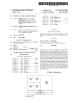
US007970030B2
(12) United States Patent
(10) Patent N0.:
Rizoiu et a].
(54)
US 7,970,030 B2
(45) Date of Patent:
DUAL PULSE-WIDTH MEDICAL LAsER
(56)
Jun. 28, 2011
References Cited
WITH PRESETS
U.S. PATENT DOCUMENTS
75
I nvent ors: I 0ana_ M . izoiu,
I S an C1 ement e, CA
(Us), Dmltl‘l 301113011550", Dana P011“,
CA (US)
3,051,905 A
3,051,906 A *
8/1962 Haynes
55/1962 Haynes ,,,,,,,,,,,,,,,,,,,,,,, ,, 327/105
3,515,938 A *
3,578,986 A *
6/1970
5/1971
7/1972 Houldcroft et al.
7/1972 Dahlinger
(73)
Assignee: Biolase Technology, Inc., Irvine, CA
(US)
3,679,863 A
3,679,998 A
(*)
Notice:
Subject to any disclaimer, the term of this
3914548 A
patent is extended or adjusted under 35
4,005,333 A
3,711,725 A *
.
.
3,991,296 A
U-S-C- 15403) by 183 days-
Filed:
DE
(
Jun. 4, 2009
Related U 5 Application Data
(63)
Kojima et a1.
M977 Nichols
3840126 A1
5/1990
Continued
Prior Publication Data
US 2009/0141752 A1
11/1976
FOREIGN PATENT DOCUMENTS
Feb. 9, 2009
(65)
Johannessen ............... .. 307/108
10/1975 Fniidman et a1‘
(Continued)
(21) Appl' NO‘: 12/368’266
(22)
1/1973
Morse .......... ..
..
McGuf?n et a1. ........... .. 327/397
Continuation-in-part of application No. 11/ 191,594,
?led on Jul. 27, 2005, noW Pat. No. 7,630,420, Whichis
)
OTHER PUBLICATIONS
Cook, “Pulse Forming Network Investigation”, Aug. 1975, Thesis at
Texas Tech University.*
_
(commued)
a continuation-in-part of application No. 11/033,032,
(60)
?led on Jan. 11, 2005, noW abandoned, Which is a
continuation-in-part of application No. 11/203,400,
?led on Aug‘ 12’ 2005’ now abandoned‘
Primary Examinerijessica T Smltz
Assistant Examiner i Joshua King
(74) Attorney, Agent, or Firm * Stout, Uxa, Buyan &
Provisional application No. 60/591,933, ?led on Jul.
Mullins, LLP
27, 2004, provisional application No. 60/601,415,
(51)
Int. C].
A medical laser device is described that generates a laser
H01S 3/00
(52)
(58)
(200601)
beam controllable With presets as to pulse duration, pulse
us. Cl. .................. .. 372/3804; 372/3806; 372/25;
repetition rate, Power and energy Per pulse- The device also
372/30; 372/31; 372/3802; 372/70; 606/10;
606/1 1
provides presets With respect to Water and air outputs. Para
metric values for poWer, pulse duration, pulse repetition rate,
Field of Classi?cation Search ............. .. 372/3806,
372/3804 25 30 31 3802 70. 606/10
606/11
and energy Per Pulse as Well as for Water and air Settings may
be programmed by an end user and stored as presets.
See application ?le for complete search history.
100 x
105
2
Hi Voltage
Power
Supply
20 Claims, 8 Drawing Sheets
165
2 f 170
US 7,970,030 B2
Page 2
US. PATENT DOCUMENTS
4,087,705
4,276,518
4,550,275
4,724,299
4,770,811
4,826,431
4,862,888
4,908,030
4,910,438
4,913,142
4,931,047
4,985,027
5,086,378
5,092,773
5,092,864
5,102,410
5,151,029
5,199,870
5,221,561
5,237,331
5,242,454
5,263,950
5,267,856
5,313,481
5,318,562
5,334,019
5,374,266
5,388,988
5,401,171
5,409,376
5,498,935
5,552,675
5,554,172
5,570,182
5,611,797
5,694,046
5,723,864
5,729,562
5,741,247
5,755,751
5,764,672
5,785,521
5,820,627
5,825,958
5,828,803
5,869,805
6,080,148
6,083,218
6,106,516
6,118,521
6,193,711
6,223,987
6,231,567
6,254,597
6,288,499
6,315,772
6,350,123
6,389,193
6,449,301
6,512,782
6,561,803
6,567,582
6,669,685
6,701,181
6,878,899
5/1978
6/1981
10/1985
2/1988
9/1988
5/1989
9/1989
3/1990
3/1990
4/1990
6/1990
1/1991
2/1992
3/1992
3/1992
4/1992
9/1992
4/1993
6/1993
8/1993
9/1993
11/1993
12/1993
5/1994
6/1994
8/1994
12/1994
2/1995
3/1995
4/1995
3/1996
9/1996
9/1996
10/1996
3/1997
12/1997
3/1998
3/1998
4/1998
5/1998
6/1998
7/1998
10/1998
10/1998
10/1998
2/1999
6/2000
7/2000
8/2000
9/2000
2/2001
5/2001
5/2001
7/2001
9/2001
11/2001
2/2002
5/2002
9/2002
1/2003
5/2003
5/2003
12/2003
3/2004
4/2005
6,902,290 B2
7,097,639 B1
7,415,050 B2
Barnes
Ferguson
O’Loughlin
Hammeke
Myers
Fujimura et a1.
Yessik
Linkow et al.
Farnsworth
Kittrell et al.
Broadwin et al.
Dressel
Prince
Levy
Hayes et al.
Dressel
Levy
Steiner et al.
Flicstein et al.
Henderson et al.
Gundlach et al.
L’Esperance, Jr.
Wolbarsht et a1.
Cook et al.
Levy et al.
Goldsmith et al.
Kataoka et a1.
Goisser et al.
Paghdiwala
Murphy
McMahan et al.
Lemelson
Horner et al.
Nathel et al.
George
Hillerich et al.
Atkinson et a1.
Birx et al.
RiZoiu et al.
Eckhouse
Ukita et a1.
RiZoiu et al.
Rosen et al.
Gollihar et a1.
Eckhouse
2002/0149324 A1
6/2005
8/2006
8/2008
10/2002
Watts et a1.
Almeida
RiZoiu et al.
RiZoiu et al.
2003/0069567 A1 *
4/2003
2003/0100824 A1
5/2003 Warren et a1.
2003/0227953 A1*
12/2003
Eckhouse et al. ............... .. 606/9
Hsia et a1. ..................... .. 372/53
2005/0137655 A1
6/2005 MacFarland
2005/0143792 A1
6/2005 Jay
2006/0020309 A1
1/2006 Altshuler et al.
FOREIGN PATENT DOCUMENTS
DE
EP
EP
EP
EP
EP
GB
GB
JP
JP
JP
JP
JP
JP
WO
W0
WO
W0
4138468
0181199
0912833
0454312
0454312
9641657
2 023 330
2297610
5945092
5200045
5506601
11511386
200301465
2003070722
9004358
97 07928
9707928
97 45165
A2
A3
A
A
A
A
A1
A3
3/1993
5/1986
9/1986
10/1991
10/1991
12/1995
12/1979
8/1996
3/1984
8/1993
9/1993
10/1999
1/2003
3/2003
5/1990
3/1997
3/1997
4/1997
OTHER PUBLICATIONS
Cook, “Pulse Forming Network Investigation”, Aug. 1975, Thesis at
Texas Tech University.*
Supplementary European Search Report, EP 05711358 (PCT/
US2005/000852), mailed Feb. 8, 2010.
International Search Report, Jun. 30, 2008, PCT/US08/051963.
International Search Report, May 23, 2008, PCT/US08/051967.
International Search Report & Written Opinion, Sep. 2, 2005, PCT/
US05/00849.
International Search Report & Written Opinion, Jul. 31, 2006, PCT/
US06/00989.
International Search Report & Written Opinion, Oct. 25, 2006, PCT/
US05/28891.
International Search Report, Dec. 10, 1998, PCT/US98/12357.
Beyer et a1.
Written Opinion, Apr. 15, 1999, PCT/US98/12357.
Damasco et a1.
European Search Report, Jun. 6, 2005, EP 05 07 5231.
Partial European Search Report, Apr. 6, 2000, EP 98 92 9060.
TS. Fahlen, Ef?cient Quarter-Joule KrF Laser with Corona
PreloniZation, IEEE Journal of Quantum Electronics, vol. QE-15,
No. 5, pp. 311-312. May 5,1979.
Bernard Grob, Basic Electronics, Glencoe division of Macmillan/
McGraw-Hill, pp. 690-681. 1989.
New LaseriMatter Interaction Concept to Enhance Tissue Cutting
Ef?ciency by Ioana M. RiZoiu and Larry G. DeShaZer, published in
SPIE col. 2134A Laser-Tissue Interaction V(1994)/ 309.
RiZoiu, Ioana and Levy, Guy C. “Ef?ciency of Bone Ablation with an
Chou
Massengill
Jung et a1.
Connors et al.
Knowles et al.
RiZoiu et al.
RiZoiu et al.
RiZoiu et al.
Marchitto et al.
RiZoiu et al.
Kimmel et al.
Wu et al.
Hsia et a1.
RiZoiu et al.
RiZoiu et al.
RiZoiu et al.
Tang et al.
Smart
NdzYAG Laser Beam Delivered with a Cooling Spray” SPIE vol.
1882 Laser-Tissue Interaction IV (1993), pp. 316-321.
RiZoiu, Ioana and Levy, Guy C. “Morphological Changes of Dentin
and Enamel after Ablation with an Experimental Laser System” SPIE
vol. 2128, pp. 282-288.
* cited by examiner
US. Patent
Jun. 28, 2011
Sheet 1 of8
US 7,970,030 B2
I
10w
PROVIDE FIRST HIGH VOLTAGE OUTPUT FROM
HVPS, CAPABLE OF DRIVING FIRST PFN
7
15v"
PROVIDE SECOND HIGH VOLTAGE OUTPUT FROM
HVPS, CAPABLE OF DRIVING SECOND PFN
I
20 v1 PROVIDE LASER PUMPING SOURCE
v
25%
GENERATE LASER PULSE
HAVING FIRST DURATION
I
GENERATE LASER PULSE
HAVING SECOND DURATION
I
FIG. 1
US. Patent
Jun. 28, 2011
Sheet 2 of8
US 7,970,030 B2
170
105
2
175
110
V1 2
1
115
Hi Voltage
101
Power
_
150
Supply
V2
140
S
130
135
C2
I 102
l/I
E~----.:\::§’-;--..l5
141f' '
-?_
L2
180
P
(a)
time
p
(b)
time
FIG. 3
time
US. Patent
Jun. 28, 2011
Sheet 3 of8
US 7,970,030 B2
US. Patent
Jun. 28, 2011
Sheet 4 of8
US 7,970,030 B2
US. Patent
Jun. 28, 2011
Sheet 5 of8
US 7,970,030 B2
US. Patent
Jun. 28, 2011
50O~I~I
Sheet 6 of8
START
US 7,970,030 B2
I
V
505 v4 SELECT PRESET NUMBER
V
510 w ENTER POWER SETTING
‘
513
ENTER PULSE DURATION
515
ENTER REPETITION RATE
\
V
520 A ENTER PULSE ENERGY
v
525 w ENTER WATER SETTING
V
530 w
ENTER AIR SETTING
I
PRESS AND HOLD BUTTON
535 ”
FOR SELECTED PRESET
545
I
54o
,
CONTINUE
‘
"
TO HOLD
,
AUDIBLE
INDICATION
550
MORE
PRESET-S
?
No
555
FIG. 8
US. Patent
Jun. 28, 2011
Sheet 8 of8
US 7,970,030 B2
I
810 w PREPARE ACCESS TO PULP CHAMBER USING G6 TIP
AND PRESETS FOR CUTTING ENAMEL AND DENTIN
I
820 v"
REMOVE CORONAL PORTION OF INFECTED!
NECTOTIC PULP USING G6 FIBER TIP
I
830 w
PERFORM INITIAL
INSTRUMENTATION
v
840 w
PERFORM LASER ROOT
CANAL ENLARGEMENT
\
850 #- MEASURE WORKING LENGTH
I
ENLARGE ROOT CANAL
USING Z2 FIBER TIP
V
870 w
ENLARGE ROOT CANAL
USING Z3 FIBER TIP
V
880 w
ENLARGE ROOT CANAL
USING Z4 FIBER TIP
I
FIG. 10
US 7,970,030 B2
1
2
DUAL PULSE-WIDTH MEDICAL LASER
WITH PRESETS
healing When tissue is brought together. The second effect can
be particularly important or relevant, for example, in grafting
applications.
CROSS-REFERENCE TO RELATED
APPLICATIONS
Prior art methods of generating these ?rst and second
effects can include employing distinctly different devices for
each type of tissue cutting. Some prior art methods of per
forming ?rst and second effect procedures may include
This application is a continuation-in-part of US. applica
tion Ser. No. 11/191,594, ?led Jul. 27, 2005 now US. Pat. No.
7,630,420 and entitled DUAL PULSE-WIDTH MEDICAL
LASER, the entire contents of Which are incorporated herein
employing systems capable of generating different Wave
lengths of electromagnetic energy. For example, Wavelengths
of about 1 pm and about 3 pm may be generated using CO2
and Erbium type lasers, respectively. Overhead time and
effort that may be required in sWitching betWeen tWo medical
by reference. US. application Ser. No. 1 1/ 191,594 claims the
bene?t of US. Provisional Application No. 60/591 ,933, ?led
Jul. 27, 2004 and entitled DUAL PULSE-WIDTH MEDI
CAL LASER, the entire contents of Which are incorporated
herein by reference. US. application Ser. No. 11/191,594 is a
devices can be disadvantages of this approach. Extra time and
attendant discomfort from a point of vieW of a patient under
going such procedures may represent additional disadvan
tages.
continuation-in-part of US. application Ser. No. 1 1/033,032,
?led Jan. 11, 2005 noW abandoned and entitled ELECTRO
MAGNETIC ENERGY DISTRIBUTIONS FOR ELEC
TROMAGNETICALLY INDUCED DISRUPTIVE CUT
TING, the entire contents of Which are incorporated herein by
reference. This application is also a continuation-in-part of
US. application Ser. No. 1 1/ 203,400, ?ledAug. 12,2005 noW
A need exists in the prior art for laser devices capable of
rapidly and ef?ciently transitioning betWeen varying charac
20
facilitating both hemostatic-type and bleeding-type tissue
cutting effects
abandoned and entitled DUAL PULSE-WIDTH MEDICAL
LASER WITH PRESETS, the entire contents of Which are
incorporated herein by reference. US. application Ser. No.
1 1/203,400 claims the bene?t of US. Provisional Application
No. 60/601,415, ?led Aug. 13, 2004 and entitled DUAL
PULSE-WIDTH MEDICAL LASER WITH PRESETS, the
entire contents of Which are incorporated herein by reference.
US. application Ser. No. 11/203,400 is a continuation-in-part
of US. application Ser. No. 11/033,032, ?led Jan. 11, 2005
25
30
noW abandoned and entitled ELECTROMAGNETIC
ENERGY DISTRIBUTIONS FOR ELECTROMAGNETI
CALLY INDUCED DISRUPTIVE CUTTING, the entire
contents of Which are incorporated herein by reference.
SUMMARY OF THE INVENTION
An exemplary implementation of the method present
invention addresses these needs by providing ?rst and second
high voltage outputs from a single poWer supply. A laser
pumping source (e.g., a ?ashlamp) also can be provided, the
laser-pumping source being capable of exciting a laser that
may be used for cutting tissue. The ?rst and second high
voltage outputs drive respective ?rst and second pulse-form
ing netWorks capable of generating respective ?rst and sec
35
BACKGROUND OF THE INVENTION
ond pulse outputs that pump the laser-pumping source
according to the exemplary implementation of the method.
Pulses produced by the ?rst pulse-forming netWork may be
relatively short, and pulses produced by the second pulse
forming netWork may be relatively long.
1. Field of the Invention
The present invention relates generally to electromagnetic
energy emitting devices and, more particularly, to pulsed
teristics or modes of operation, to facilitate, for example,
different desired cutting effects or procedures such as for
40
Another embodiment of the present invention comprises an
electromagnetic energy emitting device, Which, according to
medical treatment laser devices.
an exemplary embodiment, may comprise a medical laser
2. Description of Related Art
device, Wherein the electromagnetic energy-emitting device
is capable of emitting a sequence of electromagnetic pulses
A variety of electromagnetic energy generating architec
tures have existed in the prior art. A solid-state laser system,
45
for example, generally comprises a laser rod for emitting
coherent light and a source for stimulating the laser rod to
emit the coherent light. Flashlamps are typically used as
stimulation sources for middle infrared lasers betWeen 2.5
microns (um) and 3.5 pm, such as Er, Cr:YSGG and Er:YAG
50
having ?rst durations and second durations, Wherein the elec
tromagnetic energy-emitting device is adapted to store pre
sets specifying combinations of electromagnetic pulses hav
ing ?rst durations and second durations and Wherein the
apparatus is capable of cutting tissue. One embodiment of the
medical electromagnetic energy device can comprise a con
troller capable of storing presets, Which may include param
eters that control operation of the medical electromagnetic
laser systems. The ?ashlamp is driven by a ?ashlamp current,
Which comprises a predetermined pulse shape and a prede
termined frequency.
energy device. Examples of parameters that may be stored as
The ?ashlamp current drives the ?ashlamp at the predeter
mined frequency, to thereby produce an output ?ashlamp
light distribution having substantially the same frequency as
the ?ashlamp current. This output ?ashlamp light distribution
from the ?ashlamp drives the laser rod to produce coherent
light at substantially the same predetermined frequency as the
?ashlamp current.
Medical applications, such as those requiring the excision
presets can include poWer, pulse duration, pulse repetition
55
device can include a user input panel through Which a user can
modify and save presets.
While the apparatus and method has or Will be described
60
of soft human tissue, may in some instances require or bene?t
from tWo opposite tissue effects. The ?rst effect may relate to
laser cutting of tissue With controlled hemostasis, minimal to
no bleeding, and attenuated or eliminated charring of cut
surfaces. The second effect may relate to laser cutting With
bleeding in order, for example, to stimulate post-operative
rate, energy per pulse, a Water setting, and an air setting.
Another embodiment of the medical electromagnetic energy
65
for the sake of grammatical ?uidity With functional explana
tions, it is to be expressly understood that the claims, unless
expressly formulated under 35 U.S.C. 112, are not to be
construed as necessarily limited in any Way by the construc
tion of “means” or “steps” limitations, but are to be accorded
the full scope of the meaning and equivalents of the de?nition
provided by the claims under the judicial doctrine of equiva
lents, and in the case Where the claims are expressly formu
US 7,970,030 B2
3
4
lated under 35 U.S.C. 112 are to be accorded full statutory
Although the disclosure herein refers to certain illustrated
embodiments, it is to be understood that these embodiments
are presented by Way of example and not by Way of limitation.
equivalents under 35 U.S.C. 112.
Any feature or combination of features described herein
are included Within the scope of the present invention pro
vided that the features included in any such combination are
not mutually inconsistent as Will be apparent from the con
The intent of the folloWing detailed description, although
discussing exemplary embodiments, is to be construed to
text, this speci?cation, and the knowledge of one skilled in the
art. For purposes of summarizing the present invention, cer
tain aspects, advantages and novel features of the present
embodiments as may fall Within the spirit and scope of the
invention as de?ned by the appended claims. It is to be under
stood and appreciated that the process steps and structures
cover all modi?cations, alternatives, and equivalents of the
described herein do not cover a complete architecture and
invention are described herein. Of course, it is to be under
process How for operation of electromagnetic energy (e.g.,
laser) devices. The present invention may be practiced in
stood that not necessarily all such aspects, advantages or
features Will be embodied in any particular embodiment of
the present invention. Additional advantages and aspects of
the present invention are apparent in the folloWing detailed
description and claims that folloW.
conjunction With various structures and techniques that are
conventionally used in the art, and only so much of the com
monly practiced items are included herein as are necessary to
provide an understanding of the present invention. The
present invention has applicability in the ?eld of electromag
BRIEF DESCRIPTION OF THE FIGURES
netic treatment devices in general. For illustrative purposes,
hoWever, the folloWing description pertains to a medical laser
FIG. 1 is a How diagram describing an implementation of
the method of the present invention;
FIG. 2 is a schematic diagram illustrating an embodiment
of a dual pulse-Width ?ashlamp driving circuit according to
the present invention;
FIG. 3 is a plot depicting short, long, and mixed electro
20
device and a method of operating the medical laser device to
perform tissue treatments and surgical functions.
Referring more particularly to the draWings, FIG. 1 is a
25
magnetic energy pulses generated by the dual pulse-Width
How diagram describing an implementation of the method of
the present invention. This implementation of the method
provides a ?rst high voltage output from a high voltage poWer
FIG. 5 is a partial cut-aWay diagram of a handpiece tip in
accordance With an exemplary implementation of the present
supply (HVPS) at step 10. The ?rst high voltage output is
capable of driving a ?rst pulse-forming netWork (PFN). A
second high voltage output from the HVPS is provided at step
15. The second high voltage output is capable of driving a
second pulse-forming netWork. An exemplary embodiment
of the high voltage outputs described herein can provide
about 1500 volts from the ?rst high voltage output and about
500 volts from the second high voltage output. A pumping
invention;
source, such as a laser-pumping source, is further provided at
?ashlamp driving circuit shoWn in FIG. 2 in accordance With
various aspects of the present invention;
FIG. 4 is a pictorial diagram of a delivery system capable of
transmitting electromagnetic energy to a treatment site in
according to an exemplary embodiment the present invention.
30
FIG. 5a is a detailed illustration of an embodiment of a 35 step 20 according to the implementation. In a representative
chamber for mixing spray air and spray Water in the hand
embodiment, the laser-pumping source can comprise a
piece tip of FIG. 5;
?ashlamp capable of stimulating emission of coherent light
FIG. 6 is a cross-sectional vieW of the handpiece tip of FIG.
4 taken along line 6-6' in accordance With an aspect of the
by a laser device such as, for example, an ErzYSGG or Er,
present invention;
CrzYSGG solid state laser. At step 25 of the implementation,
40
duration (i.e., Width) is generated by pumping the laser
FIG. 7 is a cross-sectional diagram of a handpiece tip taken
along line 7-7' in FIG. 4 according to another aspect of the
present invention;
FIG. 8 is a How diagram summarizing an implementation
of a method of modifying and saving speci?ed values as
45
presets in accordance With the present invention;
FIG. 9 is a block diagram of an embodiment of a medical
electromagnetic energy controller capable of modifying and
saving presets according to the present invention; and
FIG. 10 is a How diagram outlining a root canal clinical
protocol Wherein presets may be used in accordance With an
an electromagnetic energy (e.g., laser) pulse having a ?rst
50
exemplary implementation of the present invention.
pumping source With the ?rst pulse-forming netWork output.
Similarly, at step 30 a laser pulse having a second duration
may be generated by pumping the laser-pumping source With
the second pulse-forming netWork output.
An example of a circuit capable of driving a ?ashlamp from
?rst and second high voltage outputs is described beloW With
reference to FIG. 2. A relatively detailed implementation of
the circuit of FIG. 2 is disclosed in FIGS. 2p and 3p of US.
Provisional Application No. 60/591,933, ?led Jul. 27, 2004
and entitled DUAL PULSE-WIDTH MEDICAL LASER, the
entire contents of Which are incorporated herein by reference
to the extent compatible or modi?able by one skilled in the art
DETAILED DESCRIPTION OF THE INVENTION
55
to be compatible With any aspect or modi?ed aspect of the
present invention. An ErzYSGG or Er, CrzYSGG solid state
Reference Will noW be made in detail to the presently
laser, Which is capable of generating electromagnetic energy
preferred embodiments of the invention, examples of Which
having a Wavelength in a range of about 2.70 microns (um) to
2.80 pm, typically 2.78 pm, may be driven With the architec
ture of this circuit. Parameters of the ?rst and second pulse
are illustrated in the accompanying draWings. Wherever pos
sible, the same or similar reference numbers are used in the
draWings and the description to refer to the same or like parts.
It should be noted that the draWings are in simpli?ed form and
are not to precise scale. In reference to the disclosure herein,
for purposes of convenience and clarity only, directional
terms, such as, top, bottom, left, right, up, doWn, over, above,
beloW, beneath, rear, and front, are used With respect to the
accompanying draWings. Such directional terms should not
be construed to limit the scope of the invention in any manner.
60
forming netWorks may be adjusted to produce, respectively,
pulses having relatively short and long durations. In a typical
embodiment, relatively short pulses having durations of, for
example, about 140 microseconds (us) are produced by the
?rst pulse-forming netWork, and relatively long pulses having
65
durations of, for example, about 400 us are produced by the
second pulse-forming netWork. Repetition rates for the pulses
may range, for example, from about 1 to 50 pulses/second.
US 7,970,030 B2
6
5
operation of the illustrated embodiment. A user input 170,
A partial schematic diagram of an embodiment of a dual
pulse-Width analog ?ashlamp driving circuit 100 according to
Which may comprise, for example, a sWitch on a electromag
the present invention is shoWn in FIG. 2, comprising a high
netic energy housing or handset (not shoWn), may specify
parameters (e.g., user adjustable parameters) such as pulse
voltage poWer supply 105 capable of producing dual, i.e.,
respective ?rst and second, high voltage outputs 110 and 130
trated embodiment of the dual pulse-Width analog ?ashlamp
driving circuit 100 further comprises a ?rst pulse-forming
duration and/ or pulse repetition rate. In certain embodiments,
additional sWitching transistors 121 and 141, shoWn in phan
tom in FIG. 2, may be provided in order to increase current
capacity of the ?rst and second pulse-forming netWorks 101
network 101 and a second pulse-forming network 102 con
and 102.
using methods knoWn to those skilled in the art. The illus
nected to respective ?rst and second high voltage outputs 110
A relatively short current pulse 175 may be produced by
and 130. First and second pulse-forming netWorks 101 and
the ?rst pulse-forming netWork 101 in the embodiment of the
102 are further connected to a ?ashlamp 150 that may func
tion as a pumping source for a laser (not shoWn).
trated in FIG. 2. The second pulse-forming netWork 102 may
The ?rst pulse-forming netWork 101 in the illustrated
embodiment comprises a ?rst capacitor 115, a ?rst sWitching
transistor 120, (for example, an insulated gate bipolar tran
sistor (IGBT)), and a ?rst inductor 125. The ?rst capacitor
115 is connected betWeen the ?rst high voltage output 110
and ground. The ?rst high voltage output 110 further is con
nected to the ?rst inductor 125 through the ?rst sWitching
transistor 120, and the ?ashlamp 150 is electrically connected
betWeen the ?rst inductor 125 and ground. The ?rst pulse
forming netWork 101 and the second pulse-forming netWork
dual pulse-Width analog ?ashlamp driving circuit 100 illus
produce a relatively long current pulse 180 With parameters
chosen substantially as described herein.
FIG. 3 is a chart illustrating three exemplary chains (a, b, c)
of electromagnetic energy pulses capable of being produced
20
long pulses. Chain (b) illustrates relatively short pulses of
electromagnetic energy, such as laser energy, and chain (c)
102 may be similar in form to a circuit such as that shoWn in
FIG. 3 of the above-referenced US. application Ser. No.
l l/033,032 entitled ELECTROMAGNETIC ENERGY DIS
TRIBUTIONS
FOR
by an electromagnetic energy (e.g., laser) device driven by a
dual pulse-Width circuit according to the present invention,
such as a dual pulse-Width analog ?ashlamp driving circuit
100 shoWn in FIG. 2. Chain (a) illustrates electromagnetic
energy, such as laser energy, generated according to relatively
25
depicts a mixture of relatively long and short pulses. An end
user, such as a dentist or physician, as distinguished from a
ELECTROMAGNETICALLY
manufacturer or technician, may select a type of pulse chain
INDUCED MECHANICAL CUTTING. The second pulse
forming netWork 102, Which is similar in form to the ?rst
to be produced using, for example, a user input 170 (FIG. 2).
pulse-forming netWork 101, comprises a second capacitor
Long pulses generated by the embodiment illustrated in
30
135, a second sWitching transistor 140, and a second inductor
145. The second high voltage output 130 is applied to a
terminal of the second capacitor 135, Which has another ter
minal connected to ground. The second high voltage output
130 also is coupled through a second sWitching transistor 140
surface. Conversely, short pulses generated by the same
embodiment may provide for cutting With bleeding in order to
35
to the second inductor 145, Which is connected to the
?ashlamp 150.
In typical embodiments of the dual pulse-Width analog
?ashlamp driving circuit 100, ?rst and second capacitors 115
and 135 may assume values of, respectively, about 30 micro
40
45
INDUCED MECHANICAL CUTTING. According to cer
tain implementations of the present invention, use of the
methods and apparatus described herein are not restricted to
medical (or dental) applications alone, and similar methods
and apparatus contemplated by the present invention may be
per second (J/s). The second high voltage output 130 in the
50
volts at an impedance level capable of charging the second
capacitor 135 at a rate of about 1 .I/ s. The ?rst inductor 125
may comprise an inductance of about 30 microhenries (pH) to
applied in industrial applications, such as for removing and
shaping semiconductor materials.
FIG. 4 is a pictorial diagram of a delivery system capable of
transferring electromagnetic (e.g., laser) energy to a treat
ment site. The illustrated embodiment comprises an electro
about 70 pH, such as a solid core inductor having a rated
inductance of about 50 pH in an exemplary embodiment. The
second inductor 145 may comprise an inductance of about
and to perform thermal modi?cations. Examples of long
pulse and short pulse applications are described in, for
example, the above-referenced US. Provisional Application
No. 60/ 601,41 5 entitled DUAL PULSE-WIDTH MEDICAL
LASER WITH PRESETS and US. application Ser. No.
l l/ 033,032 entitled ELECTROMAGNETIC ENERGY DIS
TRIBUTIONS
FOR
ELECTROMAGNETICALLY
illustrative embodiment has a value ranging from about 1200
volts to about 1500 volts at an impedance level capable of
charging the ?rst capacitor 115 at a rate of about 1500 Joules
embodiment may range from about 200 volts to about 500
promote post-operative healing. In another application, short
pulses may be employed in the cutting of hard tissue (e.g.,
tooth enamel, dentin, bone) While long pulses may be used in
cutting soft tissue (e.g., periodontal, mucosa, liver, kidney)
farads (uF) to about 70 HF, With an exemplary value being
about 50 HF, and about 300 uF to about 600 uF, With an
exemplary value being about 400 uF. First and second capaci
tors may receive respective ?rst and second high voltage
outputs 110 and 130. The ?rst high voltage output 110 in an
FIG. 2 may be used to achieve an objective of cutting tissue
With good hemostasis, no bleeding, and no charring of a cut
55
800 pH to about 1200 uH, such as a solid core inductor having
magnetic energy (e.g., laser) handpiece 220 that connects to
an electromagnetic energy (e.g., laser) base unit 230 using a
linking element 225. The linking element 225 may comprise
an inductance of about 1 millihenry (mH). The ?ashlamp 150
a conduit 235, Which may include one or more electromag
may comprise a 450 to 900 torr source, such as a 700 torr
netic energy (e.g., laser) conduits or ?bers, tubing for air,
tubing for Water, and the like. The linking element 225 further
source. Control signals 155 and 160 from a control device 165
may be applied to terminals of transistors 120 and 140 in
order to enable operation of the ?rst pulse-forming netWork
101 or the second pulse-forming netWork 102. Enabling the
?rst pulse-forming netWork 101 may generate relatively short
electromagnetic energy pulses, and enabling the second
pulse-forming netWork 102 may generate relatively long
electromagnetic energy pulses according to a typical mode of
60
may comprise a connector 240 that joins the conduit 235 to
the electromagnetic energy base unit 230. The connector 240
may be an identi?cation connector as is described more fully
in US. application Ser. No. ll/l92,334, ?led Jul. 27, 2005
65
and entitled IDENTIFICATION CONNECTOR FOR A
MEDICAL LASER HANDPIECE, the entire contents of
Which are incorporated herein by reference to the extent com
US 7,970,030 B2
7
8
patible or modi?able by one skilled in the art to be compatible
With any aspect or modi?ed aspect of the present invention.
Waveguides 325. The re?ected light, including the ?rst por
tion 330, may be received by second mirror 320, Which
directs the re?ected light to feedback ?bers 405 (FIG. 6)
disposed in an interior of the handpiece tip 245. The feedback
The electromagnetic energy handpiece 20 may comprise an
elongate portion 222 and a handpiece tip 245, the elongate
portion 222 having disposed therein a plurality of optical
?bers 405 may transmit the re?ected light to the electromag
netic energy base unit 230 Where the re?ected light can be
?bers that may connect to, or that are the same as, the optical
?bers included in the conduit 235. A proximal (i.e., relatively
nearer to the electromagnetic energy base unit 230) portion
221 and a distal (i.e., relatively further from the electromag
netic energy base unit 230) portion 250 may be disposed at
analyZed as is described, for example, in US. application Ser.
No. 11/203,677, ?led Aug. 12, 2005 and entitled LASER
HANDPIECE ARCHITECTURE AND METHODS and
US. application Ser. No. 11/203,399, ?ledAug. 12,2005 and
respective proximal and distal ends of the electromagnetic
energy handpiece 220. The distal portion 250 has protruding
entitled CARIES DETECTION USING TIMING DIFFER
ENTIALS BETWEEN EXCITATION AND RETURN
PULSES, the entire contents of both Which are incorporated
therefrom an output ?ber tip 255 that is described beloW in
more detail With reference to FIG. 5. As illustrated, the link
ing element 225 has a ?rst end 226 and a second end 227. First
end 226 couples to a receptacle 232 of the electromagnetic
energy base unit 230. Second end 227 couples to the proximal
herein by reference to the extent compatible or modi?able by
one skilled in the art to be compatible With any aspect or
modi?ed aspect of the present invention.
FIG. 7 is a cross-sectional diagram taken through a housing
portion 335 of the electromagnetic energy handpiece tip 245
portion 221 of the electromagnetic energy handpiece 220.
The connector 240 may connect mechanically to the electro
magnetic energy base unit 230 With a threaded connection to
the receptacle 232.
FIG. 5 is a partial cut-aWay diagram of a handpiece tip 245
(cf. FIG. 4) that couples With the electromagnetic energy base
unit 230 through the linking element 225 and the elongate
portion 222 of the electromagnetic energy handpiece 220.
of FIG. 5. The illustrated embodiment depicts an output ?ber
20
tip 255 surrounded by a tip ferrule or sleeve 345, and, option
ally, glue that ?lls a cavity 350 around the output ?ber tip 255
to hold the output ?ber tip 255 in place. The housing portion
335 may comprise tip Waveguides 325 circularly disposed
25
about the output ?ber tip 255 that may receive illumination
light from the second mirror 320 (FIG. 5) and direct the
illumination light to a target as described above. In certain
The illustrated embodiment, Which is enclosed by an outer
surface 246, may receive poWer or treatment electromagnetic
embodiments, a plurality of ?uid outputs 380 may be dis
(e.g., laser) energy from the electromagnetic energy base unit
posed in the housing portion 335 of the handpiece tip 245, the
230. Typically, the treatment electromagnetic energy is trans
mitted through a Waveguide, such as treatment ?ber 300,
?uid outputs 380 being con?gured to direct, for example, a
30
disposed in the elongate portion 222 and the handpiece tip
245 as described beloW With reference to FIG. 6.According to
one embodiment, treatment electromagnetic energy 305 is
received by an internal Waveguide, such as treatment ?ber
300, and is directed toWard a ?rst mirror 315 disposed in the
mixing spray air and spray Water in the handpiece tip 245 is
shoWn in FIG. 5a. As illustrated, the mixing chamber com
prises an air intake 370 connected to, for example, tubing (not
35
distal portion 250 of the electromagnetic energy handpiece
220, Whence re?ected electromagnetic energy is directed
toWard the output ?ber tip 255. Electromagnetic energy
received by the output ?ber tip 255 may be directed toWard a
target (e. g., a treatment) surface. The output ?ber tip 255 may
be encased in a tip ferrule or sleeve 345 that, together With the
40
60/610,757, ?led Sep. 17, 2004 and entitled, OUTPUT
45
MAGNETIC-ENERGY PROCEDURAL DEVICE, the
entire contents of Which are incorporated herein by reference
to be compatible With any aspect or modi?ed aspect of the
50
FIG. 6 is a cross-sectional diagram of a portion of an
embodiment of the handpiece tip 245, the cross-section being
(FIG. 5), Whence the electromagnetic energy is directed
toWard a plurality of tip Waveguides 325 (FIG. 5) disposed in
intake 375 join, and a spray (e.g., atomiZed) mixture 385 of
Water and air may be ejected through a ?uid output 380. The
embodiment illustrated in FIG. 7 depicts three ?uid outputs
380. These ?uid outputs may, for example, correspond to,
comprise parts of, or comprise substantially all of, any of the
?uid outputs described in US. application Ser. No. 11/042,
to the extent compatible or modi?able by one skilled in the art
taken along a line 6-6' of FIG. 5. The electromagnetic energy
?ber 300 may carry electromagnetic energy that is directed
toWard ?rst mirror 315 as already described. According to
another embodiment, additional ?bers, such as illumination
?bers 400, may carry another form of electromagnetic energy,
such as visible light, blue light, and the like, Which electro
magnetic energy may be directed toWard a second mirror 320
the connector 240 (FIG. 4). The air intake 370 and the Water
intake 375, Which may have circular cross-sections about 250
pm in diameter, join at an angle 365 that may approximate
1 100 in a typical embodiment. Mixing may occur or begin to
occur in a neighborhood Where the air intake 370 and Water
as is described more fully in US. Provisional Application No.
present invention.
shoWn) that connects to, and receives air from, a spray air
connection in the connector 240 (FIG. 2). Similarly, a Water
intake 375 may connect to tubing (also not shoWn) that con
nects to and receives Water from a spray Water connection in
output ?ber tip 255, forms a removable, interchangeable unit
ATTACHMENTS CODED FOR USE WITH ELECTRO
mixture of air and Water to a target.
A detailed illustration of an embodiment of a chamber for
824, ?led Jan. 24, 2005 and entitled ELECTROMAGNETI
CALLY INDUCED CUTTER AND METHOD, the entire
contents of Which are incorporated herein by reference to the
extent compatible or modi?able by one skilled in the art to be
compatible With any aspect or modi?ed aspect of the present
55
60
invention. The ?uid outputs 380 may, as illustrated in FIGS. 4
and 7, have a circular cross-section measuring about 350 pm
in diameter.
One aspect of the present invention, as outlined in User
Manual for a Waterlase® All-Tissue Laser for Dentistry (ref
erenced herein as “the incorporated Waterlase® User
Manual”), the entire contents of Which are incorporated
a housing 335 as is more particularly described beloW With
herein by reference, includes programmed parameter values
reference to FIG. 7. Another implementation of the present
invention receives re?ected light from a target surface, a ?rst
referred to herein as presets, the presets being applicable to
various surgical procedures. Presets may be programmed at a
portion 330 of the re?ected light being received from the
output ?ber tip 255, and a second portion of the re?ected light
(not shoWn) being received from the plurality of tip
65
time of manufacture of a device, in Which case the presets
may be referred to as pre-programmed presets. Alternatively
or additionally, presets may be generated or modi?ed and
US 7,970,030 B2
9
10
stored by an end user. Table 2 of the incorporated Waterlase®
User Manual is reproduced herein as Table 1 and includes
examples of pre-programmed presets for general hard and
soft tissue procedures.
entered preset value or values have been stored. Until a beep
is heard (e. g., about tWo to three seconds in one embodiment),
the end user continues to hold the selected preset button at
step 545 and to Wait for the audible indication. After the
TABLE 1
audible indication is heard, the implementation continues at
step 550 With a decision, Which may be made by the end user,
Suggested Presets for General Hard and Soft Tissue Procedures
to be stored, then the implementation of the method can
as to Whether more presets are to be stored. If more presets are
Preset
#
Procedure
1
2
3
Enamel Cutting
Dentin Cutting
Soft Tissue
PoWer
Rep
Rate
Energy
Per pulse
Water
Setting
Air
Setting
(Watts)
(HZ)
(mJ)
(%)
(%)
6.0
4.0
1.5
20
20
20
300
200
75
75
55
7
90
65
11
repeat, commencing at step 505. When, for example, all pre
sets have been stored, the implementation of the method
terminates at step 555. Presets, once stored, can be recalled,
for example, according to a medical procedure to be per
formed, by pressing a preset number button on the user inter
face according to an illustrative embodiment. Returning to
Cutting
(thin tissue,
Table 1, the percent air setting and the percent Water setting
set forth therein may be directed to one or more ?uid outputs
small incisions)
4
Soft Tissue
0.75
20
37.5
0
(cf. 380 of FIGS. 5, 5a and 7) at pressures ranging from about
5 pounds per square inch (psi) to about 60 psi and at How rates
11
Coagulation
According to exemplary embodiments, a plurality of pre
20
sets (e.g., programmed settings for one or more of poWer,
repetition rate, pulse duration, pulse energy, and settings for
air and Water as shoWn in Table 1) may be established.
Although not shoWn in the table, an aspect of the present
invention comprises the inclusion of pulse duration as one of
the presets. The plurality of presets may be generated at a time
of manufacture and stored in the electromagnetic energy base
unit 230 (FIG. 4). In addition to the pre-programmed preset
values for general hard and soft tissue procedures set forth in
Table 1, combinations of customiZed values of parameters
25
30
can be stored in the electromagnetic energy base unit 230 as
neW presets. According to one implementation of the present
invention, each preset can store a pulse duration (e.g., a long
pulse mode having pulse durations selectable or variable from
ranging from about 0.5 liters/minute to about 20 liters/
minute. A liquid (e. g., Water) may be directed to one or more
of the ?uid outputs 380 at pressures ranging from about 5 psi
to about 60 psi and at How rates ranging from about 2 milli
liters (ml)/minute to about 100 ml/minute. In other embodi
ments, the air ?oW rate can go as loW as about 0.001 liters/
minute, and/or the liquid ?oW rate can go as loW as about
0.001 ml/minute. In certain implementations, a Water ?oW
rate through a Water line disposed in the electromagnetic
energy hand piece may be about 84 ml/minute (e.g., 100%),
and an air ?oW rate through an air line of the electromagnetic
energy handpiece 220 (FIG. 4) may be about 13 liters/minute
(e.g., 100%). These values may be understood in reference to
such flow rates or to other flow rates suggested in the incor
porated Waterlase® User Manual or otherWise knoWn to
those skilled in the art in the same context.
35
about 650 to about 1000 us or a short-pulse mode having a
In accordance With an aspect of the present invention, the
pulse duration of about 140 us), such as a currently-active
storing of one or more combinations of values, in Whole or in
part, as presets, may enable an end user to sWitch among the
pulse duration, as a parameter and further can store one or
presets, for example, during an operation thereby permitting
more additional parameters from a group including poWer in
Watts (W), pulse repetition rate in hertZ (HZ), energy per pulse
40
the end user to quickly and reliably accomplish multiple
procedures of a given operation. E?iciency may be increased
in millijoules (ml), Water setting (%) and air setting (%).
along With accuracy, such as in the context of relatively com
FIG. 8 is a How diagram summarizing an implementation
of a method of modifying and saving predetermined or pre
ferred values as presets. The illustrated implementation com
mences at step 500 and can continue by selecting a preset
plex operations that implement combinations of short-pulse
mode procedures and long-pulse mode procedures.
FIG. 9 is a block diagram of an exemplary embodiment of
45
number at step 505 after Which a poWer setting can be entered
at step 510. According to one embodiment, a user interface on
an electromagnetic energy base unit comprises a plurality of
buttons, including preset buttons, and a display, Whereby an
end user, as distinguished from a manufacturer or technician,
50
a medical electromagnetic energy (e.g., laser) controller 600
capable of modifying and saving presets according to an
aspect of the present invention. The illustrated embodiment,
Which may be disposed, for example, in an electromagnetic
energy base unit 230 (FIG. 4), comprises a processor 605
(e.g., a microprocessor), Working memory 610, nonvolatile
may select a preset by pressing a button associated With the
memory 615, permanent memory 625, and a user interface
selected preset. A poWer setting, Which may relate, for
685. The embodiment further comprises an electromagnetic
energy (e.g., laser) control interface 670, a Water control
interface 675, and an air control interface 680. The aforemen
example, to an emitted poWer level of an electromagnetic
energy (e.g., laser) beam, may be entered by pressing buttons
(e.g., poWer up/doWn buttons) on the keypad in a manner
55
more of pulse duration, repetition rate, pulse energy, Water
setting, and air setting may be entered at respective steps 513,
515, 520, 525, and 530, for example, by pressing up/doWn
buttons corresponding to respective values for pulse duration,
repetition rate, pulse energy, Water setting, and air setting.
60
ing, such as laser housing 230 (FIG. 4)), then stores the
holding the selected preset button at step 535 While Waiting at
step 540 for an audible noti?cation (e.g., a beep) that the
(RAM)), the nonvolatile memory 615, the permanent
memory 625, and other system elements, such as a clock (not
shoWn), may be implemented on a single microcontroller
chip as an application-speci?c integrated circuit (ASIC). In
After the values (e.g., one or more of the values) have been
entered, an embodiment of an electromagnetic energy hous
entered preset values in response to an end user pressing and
tioned elements of the embodiment are interconnected by a
system bus 665 that facilitates communication among the
elements. The illustrated embodiment further comprises a
user input panel 700. In some embodiments, the processor
605, the Working memory 610 (e.g., random access memory
knoWn to those skilled in the art. Similarly, values for one or
65
other embodiments, the electromagnetic energy control inter
face 670, the Water control interface 675, the air control
interface 680, and user interface 685 further may be imple
mented on the same chip. In yet other embodiments, the latter
US 7,970,030 B2
11
12
four elements may be implemented on a companion chip to
inputs provided by the end user. The user interface control
the microcontroller chip. These and other equivalent imple
mentations are contemplated by the present invention.
instruction sequence 730 further may cause the processor 605
to activate the speaker 735.
Referring again to FIG. 8, and With continued reference to
The nonvolatile memory 615 may be con?gured to have
stored therein presets 620. The illustrated embodiment com
FIG. 9, an end user may, for example, modify and store a set
of preset values. The end user may select a present number at
prises four presets identi?ed as #1, #2, #3, and #4. Default or
pre-programmed values for the presets 620 may be stored in
step 505 and may press one of the plurality of preset buttons
695 on the user input panel 700. The user interface 685 may
receive an input according to the selected preset number on
user communication line 690. The user interface 685 further
nonvolatile memory 615 at a time of manufacture of the
medical electromagnetic energy controller 600. HoWever,
because they are stored in nonvolatile memory 615, Which
can be altered, values of the presets can be changed under
end-user control. Once changed, the stored preset values are
retained in the nonvolatile memory 615, Which is capable of
maintaining integrity of stored data even in an absence of
may communicate With the processor 605 according to the
end-user input. The processor 605 may execute the user inter
face control instruction sequence 730 that minimally may
cause the processor 605 to update content of the function
electrical poWer being supplied to the medical electromag
display strip 705 and the value display strip 710 according to
netic energy controller 600,
The permanent memory 625, Which may be programmed at
information received from the user interface 685. Similar
interactions betWeen the processor 605 and the user input
panel 700 may occur according to the user interface control
instruction sequence 730 as Will be understood by those
skilled in the art. Subsequent to selecting a preset number at
step 505, the end user may press the SELECT button 720 on
a time of manufacture of an ASIC, for example, may have
instruction sequences stored therein that may, When executed
by the processor 605, cause the medical electromagnetic
energy controller 600 to perform functions according to the
present invention. These instruction sequences in the illus
20
the user input panel 700 until, for example, a POWER indi
trated embodiment can include an executive instruction
cation is observed in the function display strip 705 according
sequence 630, an electromagnetic energy (e.g., laser) control
to step 510 of FIG. 8. The end user then may enter a poWer
instruction sequence 635, a Water control instruction
sequence 655, an air control instruction sequence 660, and a
user interface control instruction sequence 730. The electro
magnetic energy control instruction sequence 635 may, com
prise, as examples, a poWer control instruction sequence 640,
a pulse duration control instruction sequence 638, a repetition
rate control instruction sequence 645, and a pulse energy
control instruction sequence 650. The permanent memory
625 in this and other embodiments may have stored therein
additional instruction sequences related, for example, to elec
tromagnetic energy handpiece functions tangential to or out
side of the immediate scope of the present invention. For
example, the permanent memory 625 may contain an instruc
25
setting by, for example, observing a numerical value corre
sponding to a currently-active poWer setting in the value
display strip 710 and pressing the increment button 715 to
thereby increase the poWer setting. The end user also may
decrease the poWer setting by pressing the decrement button
30
725. In either case, the end user may continue to press the
increment button 715 and/or the decrement button 725 until a
desired value for poWer is displayed in the value display strip
710. The end user may again press the SELECT button 720 to
35
magnetic energy pulse duration) according to step 513 of
FIG. 8. Again, the user interface instruction sequence 730
may cause the processor 605 to present in the value display
tion sequence that controls electromagnetic energy pulse
shape according to an end-user input as Well as similar types
of instruction sequences related to operation of medical elec
change the content of the function display strip 705 to, for
example, PUL DUR (indication, for example, of an electro
40
strip 710 a value currently stored for electromagnetic energy
pulse duration according to the selected preset. The end user
tromagnetic energy (e. g., laser) systems. The executive
then may adjust the value displayed in the display strip 710 by
instruction sequence 630 minimally may cause the processor
605 to schedule and coordinate the aforementioned instruc
pressing the increment and decrement buttons 715 and 725 in
a manner similar to that already described.
The end user may continue to initiate updating of param
tion sequences as Well as additional instruction sequences not
described herein.
According to an exemplary mode of operation, the embodi
45
interface control instruction sequence 730 may cause the
ment of FIG. 9 receives an input from an end user, i.e., an
end-user input, on a user communication line 690. The user
communication line 690 may be connected to the user input
panel 700, Which may have disposed thereon a plurality of
50
display strip 705, such as a liquid crystal display (LCD), may
shoWn), thereby Waiting for about 2 to 3 seconds after Which
55
user communication line 690, the user interface 685 may
communicate information betWeen the user input panel 700
and the processor 605. For example, the processor 605 may
execute the user interface control instruction sequence 730
that minimally may cause the processor 605 to update a
processor 605 to store updated parameter values in, for
example, Working memory 610. When the end user completes
updating desired parameter values, the end user may press
and hold the selected one of the preset buttons 695. The user
interface control instruction sequence 730 may cause the
processor 605 to execute a timing instruction sequence (not
preset buttons 695, a SELECT button 720, an increment but
ton 715, a decrement button 725 and a speaker 735.A function
display a function chosen according to the SELECT button
720, and a numerical parameter value may be displayed in a
value display strip 710. When an end-user input is received on
eter values for selected preset numbers according to, for
example, steps 515, 520, 525, and 530 of FIG. 8. The user
60
time interval the user instruction control instruction sequence
730 may cause the processor to move the updated parameter
values to nonvolatile memory 615 and to update content of the
selected one of the stored presets 620. The user interface
control instruction sequence 730 then may cause the proces
sor 605 to transmit an audible signal (e.g., a beep) to the
speaker 735.
display, such as a message presented in the function display
Several operations are noW described that involve combi
strip 705 and/or a value presented in the value display strip
710, according to the end-user input. In particular, the user
nations of short-pulse procedures and long-pulse mode pro
interface control instruction sequence 730 further may cause
the processor 605 to interact With the user interface 685, for
example, to modify and store preset values 620 according to
cedures. In many cases, for a given operation, values for some
65
or all parameters (eg poWer, pulse repetition rate, etc.) may
be different for short-pulse mode procedure as compared to
values for long-pulse mode procedures. Although the opera
US 7,970,030 B2
13
14
tions outlined below are described in a context of a cutter,
setting (manual or preset) of operating parameters. The same
such as a Waterlase® device, operating in distinct short-pulse
or subsequent displays may instruct the end user then to
(cf. FIG. 3(b)) and long-pulse (cf. FIG. 3(a)) modes at differ
perform, for example, laser root canal enlargement at step 840
using a Z2 output ?ber tip. A similar display or displays may
ent times, it should be understood that modi?ed, but not
necessarily interchangeable, implementations can include
instruct the end user to measure Working length using a Z2
long pulses interspersed in short-pulse mode pulse sequences
output ?ber tip at step 850 and to enlarge the root canal at step
860 using the Z2 output ?ber tip. At step 870 the end user may
be instructed by the same or subsequent displays to enlarge
and/or can include short pulses interspersed in long-pulse
mode pulse sequences. For example, one or more of the beloW
long-pulse mode procedures of a given operation may, as an
the root canal using a Z3 output ?ber tip. The same or subse
alternative to a long-pulse mode pulse sequence of only long
pulses, implement a long-pulse mode pulse sequence com
quent displays then may instruct the end user to enlarge the
root canal using a Z4 output ?ber tip at step 880. All of the
preceding displays further may instruct the end user to use
prising a plurality of alternating long and short pulses (cf.
FIG. 3(c)). In the examples that folloW, operations that may be
appropriate operating parameter settings (e.g., manual or pre
set values for electromagnetic energy (e.g., laser) poWer,
pulse duration, pulse repetition rate, pulse energy, and set
tings for Water and air).
implemented using a cutter, such as a Waterlase® device, are
elucidated for various operations Wherein short-pulse modes
may be used for some procedures of a given operation and
long-pulse modes may be used for other procedures of the
operation. These examples include modi?cation of root canal
Steps 810-880 of the root canal clinical protocol described
in FIG. 10 may be performed in Whole or in part With, for
surfaces, modi?cation of prepared cavity surfaces, modi?ca
tion of root surfaces at or beloW the gum line (including
20
example, a short-pulse mode (Wherein the parameters for
modifying a prepared cavity surface to enhance bonding and
steps 840-880 may be recalled for the operation using a pre
further including desensitiZing or otherWise treating an outer
set). A before and/ or after irrigation step (cf. step 9 in Appen
dix C of the incorporated Waterlase® User Manual) may
include or be preceded by a modi?cation of surfaces (e.g.,
side-Wall surfaces) of the root canal using, for example, the
root surface), and apicoectomy procedures.
Modi?cation of Root Canal Surfaces
Appendix C of the incorporated Waterlase® User Manual
25
describes a root canal clinical protocol that is abstracted in
Waterlase® in long-pulse mode to modify (e.g., close)
FIG. 10. Operating parameters for the procedure as delin
eated in the incorporated Waterlase® User Manual (e.g.,
exposed tubule structures or openings. The cutter, Which may
comprise, for example, a Waterlase® device, may be set (e. g.,
poWer, pulse repetition rate, energy per pulse, Water percent
age and/or air percentage, and, as another option, pulse dura
tion) may be entered manually or may be recalled using a
preset, such as a preset presented above in Table 1.
In accordance With an aspect of the present invention, a
monitor that may form part of the electromagnetic energy
base unit 230 (FIG. 4) may instruct use of various output
attachments, such as output ?ber tips. According to an exem
plary implementation, various output attachments are
embodied in the form of output ?ber tips identi?ed as G6, Z2,
Z3, and the like. The monitor may instruct use of the various
output attachments at varying times in a given operation or
procedure. An embodiment of the present invention may
30
by the end user activating a preset, or manually) to a poWer of
about 1.5-2 W, a pulse repetition rate of about 30 HZ, an
35
energy per pulse of about 50 m], a Water setting of about 20%,
and an air setting of abut 40%. Surfaces of the root canal may
then be modi?ed using a protocol similar to that of steps
840-880. For example, Z2, Z3 and/or Z4 output ?ber tips can
be successively used for about 5-10 upWard strokes each
Wherein, for example, each upWard stroke involves about 5
seconds of lasing and Wherein the doWnWard strokes do not
entail lasing. In another embodiment, the long-pulse proce
dure may use only a Z4 output ?ber tip, to the exclusion of the
40
include a visual indication of color codes or topography codes
indicative of and corresponding to output tips having a color
pattern, various attachments being used at various times, as is
more fully described in the above-referenced U.S. Provi
any of those knoWn to those skilled in the art or suggested in
45
sional Application No. 60/610,757, ?led Sep. 17, 2004,
entitled OUTPUT ATTACHMENTS CODED FOR USE
WITH ELECTROMAGNETIC-ENERGY PROCEDURAL
DEVICE.
In the context of implementing part or all of steps 1-8 of the
With techniques suggested in the incorporated Waterlase®
rated Waterlase® User Manual) or otherWise knoWn to those
50
skilled in the art. After preparation of the cavity, but before
?lling thereof, the prepared cavity surface may be modi?ed
to, for example, enhance bonding properties. The cutter (e. g.,
Waterlase®) may be set (e.g., by the end user activating a
55
chamber at step 810 using a G6 output ?ber tip at a setting
(manual or preset) of operating parameters appropriate for
preset, or manually), to a poWer of about 2.5-3 W, a pulse
repetition rate of about 30 HZ, an energy per pulse of about
80-100 m], a Water setting of about 10-15%, and an air setting
of abut 25-30%. Surfaces of the prepared cavity may then be
modi?ed using a circular motion covering all bonding sur
faces for a time of, for example, 5-15 sec.
cutting enamel and dentin. For example, presets #1 and #2 as
presented in Table 1 above may be used to prepare access to
the pulp chamber. The ?rst display or a subsequent display
the incorporated Waterlase® User Manual, may be recalled
for the procedure using a preset, or manually), in combination
User Manual (c.f. Tables 2-6 and related text of the incorpo
root canal clinical protocol described in Appendix C of the
incorporated Waterlase® User Manual, Which steps corre
spond to steps 810-880 of FIG. 10, a ?rst display on, for
example, an electromagnetic energy base unit 230 (FIG. 4)
may instruct that the end user prepare access to the pulp
Z2 and Z3 output ?ber tips.
Modi?cation of Prepared Cavity Surfaces
A cavity is ?rst prepared using, for example, a short-pulse
mode (Wherein, for example, the parameters, Which may be
may instruct that the end user then use the same output ?ber
Modi?cation of Outer Root Surfaces at or BeloW Gum Line
Outer root surfaces can be modi?ed using a long-pulse
tip at step 820 to remove the coronal portion of the infected/
mode to perform at least one of (1) modifying a prepared
60
necrotic pulp at an appropriate setting of operating param
cavity surface to enhance bonding and (2) desensitiZing or
eters. According to one embodiment, the operating param
otherWise treating the outer root surface. Either of these
eters may be preset. The same or a subsequent display may
instruct that the end user perform initial instrumentation
using a Z2 output ?ber tip at step 830 using an appropriate
65
operations can be implemented by setting (e.g., via the end
user activating a preset, or manually) the cutter (e.g., Water
lase®) to, for example, a poWer of about 3 W, a pulse repeti
US 7,970,030 B2
15
16
Apicoectomy Procedures
tion rate of about 30-40 HZ, an energy per pulse of about
80-100 m], a Water setting of about 15-20%, and an air setting
of about 40%.
During cutting of gingival tissue in an apicoectomy proce
dure as described in Appendix C of the incorporated Water
1. Modifying a Prepared Cavity Surface to Enhance Bond
lase® User Manual, bleeding of the gingival tissue may be
attenuated or treated by sWitching to a long-pulse mode (e. g.,
via the end user activating a preset, or manually), Which, for
example, may con?gure the cutter to a poWer of about 1-2 W,
a pulse repetition rate of about 40-50 HZ, an energy per pulse
of about 20-40 m], a Water setting of about 0%, and an air
1ng
For operations on outer root surfaces involving modifying
a prepared cavity surface to enhance bonding, if a caries is
present, for example, on or just beloW the gum line on the
outer root surface, the cutter (e.g., Waterlase®) may be imple
setting of about 10-20% and/or to combinations of values as
disclosed in Table 4 of the incorporated Waterlase® User
Manual. Short-pulse mode procedures as set forth in a section
mented to remove the carious tissue in a short-pulse mode.
Short-pulse mode parameters generally knoWn to those
skilled in the art or suggested by the incorporated Waterlase®
of Appendix C discussing apicoectomy procedures may be
User Manual may be used. According to an exemplary
embodiment, the parameters are recalled for the procedure
enabled using presets. With reference to the apicoectomy
procedure set forth in Appendix C of the incorporated Water
lase® User Manual, as modi?ed by the disclosure herein,
other implementations may comprise either of the tWo (i.e.,
long and short pulse) soft-tissue cutting modes being used or
(via a preset, or manually) using techniques suggested in, for
example, Tables 2-6 and related text of the incorporated
Waterlase® User Manual. After preparation of the cavity on
the outer root surface, but before ?lling thereof, the prepared
cavity surface may be modi?ed to, for example, enhance
bonding properties. The cutter (e.g., Waterlase®) may be set
combined in any sequence or proportion to include, for
20
mode cutting, visa versa, and/or treatments using long pulses
interspersed in short-pulse mode pulse sequences and/or
(e.g., by the end user activating a preset, or manually), to a
long-pulse mode and to the settings disclosed in the preceding
section entitled Modi?cation of Prepared Cavity Surfaces,
and surfaces of the prepared cavity may then be modi?ed
using a circular motion covering pertinent bonding surfaces
short pulses interspersed in long-pulse mode pulse
25
for an exemplary time of 5-15 seconds. In modi?ed embodi
ments, the short-mode and long-mode pulse procedures may
be sWapped in time or combined.
2. DesensitiZing or Otherwise Treating the Outer Root
Surface
For desensitiZing or otherWise treating the outer root sur
example, short-pulse mode cutting folloWed by long-pulse
sequences. This disclosure canbe extended to other soft tissue
procedures, such as frenectomies. As an example of an api
coectomy procedure, a ?rst preset can be activated by the end
user to facilitate short-pulse mode incising/cutting, folloWed
by the end user activating a second preset to facilitate a
long-pulse mode treatment Which may induce, for example,
30
reduced-bleeding cutting or coagulation (via lasing the tissue
for about 5-10 seconds), Whereby the operation may continue
face, to the extent exposed, the output ?ber tip can be posi
With additional switches to or betWeen one or more of the tWo
tioned and activated about 2-5 millimeters (mm) from the
surface (depending on sensitivity). Lasing can be applied
using a circular motion, making sure the patient does not feel
pain. In a particular example, lasing may be initiated With the
output ?ber tip about 5 mm from the surface and, While lasing
With a circular motion, the output ?ber tip may be brought
(i.e. long-pulse and short-pulse) cutting modes.
Corresponding or related structure and methods described
35
Wherein such incorporation includes corresponding or related
closer and closer to a distance of about 2-3 mm from the
surface While making sure the patient does not feel pain. An
40
s75 output ?ber tip, manufactured by BioLase Technology,
Inc., of San Clemente, Calif., may be used, and the lasing
To the extent an outer root surface to be treated is not 45
exposed, obstructing gum tissue may be removed in a long
pulse mode by setting (e.g., via the end user activating a
preset, or manually) the cutter (e.g., Waterlase®) to, for
50
55
incorporated Waterlase® User Manual, (cf. Tables 2-6 and
related text), may be recalled for the procedure via a preset, or
manually) using techniques knoWn to those skilled in the art
in vieW of this disclosure or suggested by the incorporated
Waterlase® User Manual (c.f., Tables 2-6 and related text). In
modi?ed implementations, in the context of the present pro
Nos. 5,741,247; 5,785,521; 5,968,037; 6,086,367; 6,231,567;
6,254,597; 6,288,499; 6,350,123; 6,389,193; 6,544,256;
6,561,803; 6,567,582; 6,610,053; 6,616,447; 6,616,451;
6,669,685; 6,744,790 and 6,821,272. For example, output
optical energy distributions from the ?ashlamp 150 of the
illustrated embodiment of the present invention may be useful
short-pulse mode (Wherein, as With the long-pulse mode
implementation, parameters knoWn or apparent to those
skilled in the art, in vieW of this disclosure or suggested by the
structure (and modi?cations thereof) in the folloWing patents
Which may be (i) operable With, (ii) modi?ed by one skilled in
the art to be operable With, and/ or (iii) implemented/used With
or in combination With any part(s) of, the present invention
according to this disclosure, that/those of the patents, and the
knoWledge and judgment of one skilled in the art: US. Pat.
application time to treat the exposed root surface may be
about 30-60 seconds.
example, a poWer of about 1-2 W, a pulse repetition rate of
about 40-50 HZ, an energy per pulse of about 20-40 m], a
Water setting of about 0%, and an air setting of about 10-20%.
In another embodiment, the cutter may be implemented in a
in the folloWing patents assigned to BioLase Technology,
Inc., are incorporated herein by reference in their entireties,
for optimiZing or maximiZing a cutting effect of an electro
magnetic energy source, such as a laser that is driven by the
?ashlamp 150. The electromagnetic energy output can be
directed, for example, into ?uid (e.g., an atomiZed distribu
tion of ?uid particles) above a target surface. An apparatus for
directing electromagnetic energy into an atomiZed distribu
tion of ?uid particles above a target surface is disclosed in the
above-referenced US. Pat. No. 5,574,247. The long and/or
short pulses can impart large amounts of energy into the ?uid
(e.g., atomiZed ?uid particles) Which preferably comprises
60
Water, to thereby expand the ?uid (e.g., ?uid particles) and
apply disruptive (e.g., mechanical) cutting forces to the target
surface.
cedure, either of the tWo modes can be combined in any
sequence or proportion to include, for example, long-pulse
In vieW of the foregoing, it Will be understood by those
mode cutting folloWed by short-pulse mode cutting, visa
versa, and/or treatments using long pulses interspersed in
short-pulse mode pulse sequences and/or short pulses inter
spersed in long-pulse mode pulse sequences.
skilled in the art that the methods of the present invention can
65
facilitate operation of electromagnetic energy devices, and in
particular examples medical laser devices exhibiting a capa
bility of producing laser pulses having a plurality of pulse
US 7,970,030 B2
17
18
durations. The above-described embodiments have been pro
prises providing a second high voltage output con?gured to
generate a second pulse output differing from the ?rst pulse
vided by Way of example, and the present invention is not
limited to these examples. Multiple variations and modi?ca
output in one or more of duration and poWer.
tion to the disclosed embodiments Will occur, to the extent not
3. The method as set forth in claim 2, further comprising:
mutually exclusive, to those skilled in the art upon consider
generating a pulse having a ?rst duration by pumping the
pumping source With the ?rst pulse output; and
generating a pulse having a second duration by pumping
the pumping source With the second pulse output.
ation of the foregoing description.
For example, a pumping circuit comprising a plurality
(e. g., more than tWo) of high voltage outputs and correspond
ing pulse-forming netWorks (e.g., for generating three or
more outputs of varying pulse Width) is contemplated by the
4. The method as set forth in claim 3, further comprising
generating a plurality of pulses by repetitively pumping the
present invention. The present invention may be used With or
pumping source With the ?rst pulse output.
constructed to implement different electromagnetic energy
pulse durations and varying amounts of ?uid (e.g., Water
streams, sprays or mists) in the context of, for example,
5. The method as set forth in claim 3, further comprising
generating a plurality of pulses by repetitively pumping the
laser-pumping source With the second pulse output.
Erbium-types of lasers, for facilitating, for example, multiple
6. The method as set forth in claim 3, further comprising
generating a plurality of pulses, each pulse having one of a
treatment or cutting effects such as hemostatic-type and
bleeding-type tissue cutting effects. For example, a Wave
length of about 3 um and pulse durations of 50 us and 1000 us
may be implemented to provide ?rst and second cutting
effects as desired.
20
output.
The present invention may also be used or constructed With
capacitor-charging poWer supplies in the generation of pulses
having variable duration, keeping in mind that such modi?
7. The method as set forth in claim 6, further comprising:
receiving a control input from an end user; and
cations may in some instances present issues such as limited
pulse repetition rates, relatively expensive driving circuitry,
controlling the generating of pulses according to the con
25
someWhat rectangular rather than bell-shaped current pulse
shapes, and relatively numerous, voluminous and/or heavy
the generating of a pulse having a ?rst duration comprises
generating a pulse having a duration of about 50 micro
While the invention has been described in the context of
30
seconds; and
the generating of a pulse having a second duration com
prises generating a pulse having duration of about 1000
microseconds.
9. The method as set forth in claim 1, Wherein:
being constructed for generating pulses of different lengths,
are also contemplated. Moreover, While the invention has
been described in the context of using a single poWer supply
to generate tWo pulse outputs for an electromagnetic energy
trol input.
8. The method as set forth in claim 3, Wherein:
capacitors.
?rst and second pulse-forming netWorks, it is to be under
stood that greater numbers of pulse-forming netWorks, each
similar to the ?rst and second pulse-forming networks but
?rst duration generated by pumping the laser-pumping source
With the ?rst pulse output and a second duration generated by
pumping the laser-pumping source With the second pulse
output device, implementations of the present inventionusing
the providing of a ?rst high voltage output comprises pro
viding a voltage of about 1500 volts; and
the providing of a second high voltage output comprises
three or more pulse-forming netWorks may comprise a single
poWer supply or may comprise a number of poWer supplies
10. The method as set forth in claim 1, Wherein the method
that is less than the number of pulse-forming netWorks.
35
providing a voltage of about 500 volts.
40
comprises cutting tissue.
45
tromagnetic energy output device is a laser that is pumped by
the poWer supply.
12. A method of using a poWer supply to generate dual
pulse outputs for an electromagnetic energy output device,
the method comprising:
Providing a plurality of high voltage outputs from the
poWer supply including at least a ?rst voltage of about
11. The method as set forth in claim 1, Wherein the elec
Additionally, other combinations, omissions, substitutions
and modi?cations Will be apparent to the skilled artisan in
vieW of the disclosure herein. Accordingly, the present inven
tion is not intended to be limited by the disclosed embodi
ments, but is to be de?ned by reference to the appended
claims.
What is claimed is:
1. A method of using a poWer supply to generate dual pulse
outputs for an electromagnetic energy output device, the
method comprising:
200-500 volts and a second voltage of about 1200-1500
50
providing a ?rst high voltage output iof about 1200-1500
volts from the poWer supply, the ?rst high voltage output
being capable of driving a ?rst pulse-forming netWork
tors of about 30-70 pH and 800-1200 pH, Wherein the
plurality of high voltage outputs drives the plurality of
that has a capacitor of about 30-70 HF and an inductor of
about 30-70 pH and is con?gured to generate a ?rst pulse
output; and
providing a second high voltage output ‘of about 200-500
55
13. The method of claim 10, Wherein the providing of a
plurality of high voltage outputs is performed by providing
only tWo high voltage outputs.
60
15. The method as set forth in claim 10, further comprising
providing a pumping source capable of being pumped by at
and an output from the second pulse-forming netWork,
Wherein the providing of a second high voltage output com
14. The method of claim 10, Wherein the providing of a
plurality of pulse-forming netWorks is performed by provid
ing only tWo pulse-forming netWorks.
inductor of about 800-1200 pH and is con?gured to
generate a second pulse output.
2. The method as set forth in claim 1, further comprising
least one of an output from the ?rst pulse-forming netWork
pulse-forming netWorks With signals differing in one or
more of duration and poWer.
volts from the poWer supply, the second high voltage
output being capable of driving a second pulse-forming
netWork that has a capacitor of about 300-600 HF and an
volts; and
Providing a plurality of pulse-forming netWorks having
capacitors of about 30-70 HF and 300-600 HF and induc
65
providing a laser-pumping source capable of being pumped
by the plurality of pulse-forming netWorks.
16. The method as set forth in claim 12, Wherein the
method comprises cutting tissue.
US 7,970,030 B2
19
17. The method as set forth in claim 12, wherein the elec
tromagnetic energy output device is a laser that is pumped by
the power supply.
18. An apparatus, comprising:
a device having a single poWer supply capable of supplying
a ?rst high potential output at a ?rst potential level and a
second high potential output at a second potential level,
the ?rst potential level being higher than the second
potential level;
a pumping source;
a ?rst pulse-forming netWork having a capacitor of about
30-70 HF and an inductor of about 30-70 pH and being
capable of receiving the ?rst high potential output, the
?rst pulse-forming netWork further being capable of
driving the pumping source With a ?rst signal; and
20
a second pulse-forming netWork having a capacitor of
about 300-600 HF and an inductor of about 800-1200 pH
and being capable of receiving the second high potential
output, the second pulse-forming netWork further being
capable of driving the pumping source With a signal
differing from the ?rst signal in one or more of duration
and poWer.
19. The apparatus as set forth in claim 18, Wherein the
device is a laser device and the pumping source is a laser
10 pumping source.
20. The apparatus as set forth in claim 19, Wherein the
device is constructed to facilitate cutting of tissue.