1
Your RC-7B / RC-7BE
4
Your RC-7B / RC-7BE
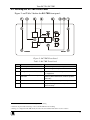
This section defines the:
Front panel of the RC-7B (see section 4.1)
Front panel of the RC-7BE (see section 4.2)
Side panel of the RC-7B and RC-7BE (see section 4.3)
4.1 Defining the RC-7B Front Panel
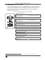
Figure 1 and Table 1 define the RC-7B front panel:
Table 1: RC-7B Front Panel
#
1
2
3
4
Feature
Configurable
Control
Buttons (4)
Mounting
holes (2)
Function
Macro Buttons for
controlling the room and
the A/V equipment
For fastening the controller
in place
Faceplate
Attachment
Holes (2)
CONFIG Port2
on 3.5mm jack
connector
For attaching the faceplate
1
to the controller
5
SIGNAL
SOURCES
Buttons
6
IR IN Receiver
Used for Windows®-based
configuration software
(driver downloads, firmware
updates and so on)
Select the input source
(from 1 to 3)
Accepts IR remote
commands (for the
IR-learner feature)3
Figure 1: RC-7B Front Panel
1 These screws should not be removed during or after mounting
2 Via the front panel, without having to remove the RC-7B from its mounting
3 Letting you configure the RC-7B directly from the remote transmitter without the need for software
4
KRAMER: SIMPLE CREATIVE TECHNOLOGY