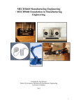
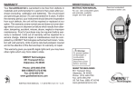
1
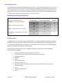
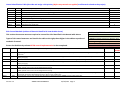
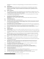
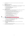
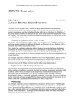
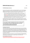
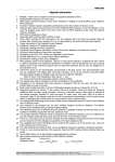
School of Aerospace, Mechanical & Mechatronic Engineering Project Risk Assessment (PRA) and Application Form ‐ (PRA Form) The School of Aerospace, Mechanical & Mechatronic Engineering (AMME) requires a Risk Assessment (RA) to be completed, reviewed and approved for all projects/experiments that are to be undertaken within the School. This form must be completed electronically. Please provide enough information to make experimental processes clear, identify all risks and hazards and proposed methods to be used to mitigate these risks and hazards. Note: No laboratory work is to be performed until the Project Risk Assessment has been assessed and APPROVED by the School’s Risk Review Committee. Part 1. Details of project/experiment participants Supervisor(s): David Rye Supervisor telephone number: 9351‐2286 Other participants: Students enrolled in MTRX3700 Main contact telephone number: 9351‐2286 Project title: MTRX3700 Major Project Work location (list all labs, workshops etc.): Raymond Kirby Robotics Teaching Lab Work start date: 2015‐10‐06 Work finish date: 2015‐10‐29 Form Submission Date: 2015‐10‐08 Does this project require any after hours access? No (If YES then project participants must follow University guidelines for afterhours access) http://sydney.edu.au/whs/guidelines/others/working_after_hours.shtml Admin Use Only: PRA number: PRAno Version 1.2 AMME‐PRA2013MMDD‐1 15/10/2015 Page 1 Part 2. Project specifics (Enter N/A if Not Applicable, add any additional information to the appendix area if necessary (include photographs of apparatus if possible). Description of project or experiment: Students work in a group of 6 or 7 students to design and implement a microprocessor‐ controlled robotic system that is able to compete in a robot jousting tournament. Further information is available in the MTRX3700 Major Project Handout (http://web.aeromech.usyd.edu.au/MTRX3700/Course_Material/labs/major/Major‐2015‐ Rev2.pdf ). Description of apparatus to be used (add figures to appendix if required): The equipment is one mobile robot assembled from mechanical and electronic components and one knight and saddle per group (total 8), plus a tilt. Further information is available in the Mobile Robot Design Notes (http://web.aeromech.usyd.edu.au/MTRX3700/Course_Material/labs/major/mobile/Mobile_R obot_Design_Notes.pdf ). Description of any fieldwork requirements: None Version 1.2 AMME‐PRA2013MMDD‐1 15/10/2015 Page 2 Part 3. Risk assessment The University of Sydney utilises a Risk Management process as required by NSW legislation. All risks and hazards associated with any project must be identified and described. These identified hazards are then given a priority based on a risk matrix (see below). Methods that will be used to control and minimise all identified hazards are then described and implemented. Please also refer to School Standard Operating Procedures associated with the project as part of the control system. Risk Matrix (to determine risk priorities) Identified Hazards ‐ think about: How severely could it hurt someone? How likely is it to hurt someone? very likely ++ could happen regularly !!! kill or disable !! several days off work ! first aid 1 2 3 likely + could happen occasionally 2 3 4 unlikely ‐ could happen, but only rarely 3 4 5 very unlikely ‐‐ could happen, but probably never will 4 5 6 Possible Hazards In consultation with any other project participants, the project supervisor and other relevant technical personnel, consider all stages of the project (including decommissioning/disposal) and any potential hazards that may be present. List and describe these hazards in the hazard table below, also assign a Risk Priority to each hazard. Some hazards to consider (this is just a guide, consider all hazards, and consult all people involved with the project): Version 1.2 Chemicals (describe expected quantities to be used) Hazardous substances (describe expected quantities to be used) Biological substances Radiation Lasers Electrical equipment Automated machinery Mechanical systems (pumps, hydraulic equipment, pneumatics, pressure vessels) Manual handling Noise Exposure to particulates Others…. AMME‐PRA2013MMDD‐1 15/10/2015 Page 3 Hazard Identification Table (describe and assign a risk priority (before any controls are applied) to all hazards related to the project) Admin PRAno PRAno PRAno PRAno PRAno PRAno PRAno PRAno Ref # HAZ1 HAZ2 HAZ3 HAZ4 HAZ5 HAZ6 HAZ7 HAZ8 Hazard description (provide plenty of detail/information) Electrical shock Battery fire / burn from hot wires due to high energy content of LiFe battery Burn from soldering Chemical leakage from battery Impact by moving robot causing injury to foot Tripping on robot Cut by sharp edge on robot Cut when using hand tools Risk Priority 3 5 4 6 5 3 5 4 Risk Control Methods (address all hazards identified in hazard table above) Hierarchy of Risk Control Measures This section documents measures required to control the risks identified in the Hazard table above. Types of risk control measures are listed in the table to the right; those higher in the table are preferred methods of control. Ensure the Risk Priority column AFTER control implementation is also completed. Admin Ref # PRAno RC1 PRAno RC2 PRAno PRAno RC3 RC4 PRAno RC5 PRAno RC6 PRAno RC7 PRAno RC8 Describe risk controls to be implemented (provide plenty of detail/information) Engineering: Lab is fitted with RCDs on 240 V circuits. Administrative: Students are expressly forbidden from working on 240 V equipment in the Lab. Administrative: Exercise caution and understand the circuits before making connections to the battery. Follow specified procedures for battery charging. Administrative: Students must be inducted before soldering. Students to follow SOP for Soldering and Defluxing. Administrative: Exercise caution and understand the circuits before making connections to the battery. Follow specified procedures for battery charging. Administrative, Isolate: Robots to be tested stationary on benches. Robots not to be run on floor until robot controller and commander are stable. Specific area on floor to be designated for testing. Administrative, Isolate: Robots to be tested stationary on benches. Robots not to be run on floor until robot controller and commander are stable. Specific area on floor to be designated for testing. Administrative: Be aware of possibility of sharp edges (although they should have already been removed).Eliminate: If sharp edge discovered, eliminate it with deburring tool or file or cover it with tape.‐ Administrative: Correct use of hand tools. Be aware of what will happen *when* (not if) a sharp tool slips. Version 1.2 1. Eliminate the hazard 2. Substitute with a lesser risk 3. Isolate the hazard with barriers, distance, time 4. Use Engineering (non‐avoidable) controls 5. Use Administrative (procedural) controls 6. Use PPE ‐ Personal Protective Equipment AMME‐PRA2013MMDD‐1 15/10/2015 Page 4 Due Date Risk Priority AFTER Control For any hazards identified below as having a Risk Priority of 1 or 2, a more extensive risk analysis must be completed using Riskware. Please complete a hazard entry in Riskware and attach to this PRA form in the appendix section. Version 1.2 AMME‐PRA2013MMDD‐1 15/10/2015 Page 5 Part 4. Standard Operating Procedures associated with the project There are a number of standard operating procedures developed by the School that may be appropriate for use in the project. These will become progressively available on the School’s WHSRM webpage. Please list any standard operating procedures associated with this project in the table below. Admin PRAno PRAno PRAno PRAno PRAno Ref # Standard Operating Procedure Name & Code SOP1 SOP2 SOP3 SOP4 SOP5 Soldering and Defluxing Part 5. Hazardous substances & dangerous goods List any hazardous substances or dangerous goods that will be used. Please refer to the University’s guidelines on the use of hazardous substances available at the following link: Hazardous Substances Admin PRAno PRAno PRAno PRAno PRAno Ref # Hazardous substance or dangerous goods HS1 HS2 HS3 HS4 HS5 Disposal Method Part 6. Training requirements List any training requirements below. All staff and students that will be involved with the project MUST be consulted when determining training plans. WHSRM Training Admin PRAno PRAno PRAno PRAno PRAno Ref # Training T1 T2 T3 T4 T5 Version 1.2 Date to be completed AMME‐PRA2013MMDD‐1 15/10/2015 Page 6 Part 7. Declaration and Approvals I have completed this Project Risk Assessment giving due consideration to the possible hazards associate with all stages of the project. I have consulted other staff that will be involved with the project when determining suitable risk control measures to be used. I have attached all MSDS relevant to the project and completed a Part A & B form for any hazards determined to be of Risk Priority 1 or 2. Students Consulted: Todd Enfield, Nicholas Dai, Jiapei Chen, Jonathon Lillia, Leo Lou, Vu Toan Tran, Jordan Jolly, Saahil Relan. Applicant(s) Name: David Rye Date: 2015‐10‐08 Applicant(s) Signature: Supervisors have a duty of care for staff and students working on projects under their supervision, signing below indicates that the project supervisor has read and been consulted during the completion of this risk assessment form. Supervisors are responsible for ensuring staff and students and trained accordingly and inducted into the relevant workspaces. Supervisor(s) Name: David Rye Date: 2015‐10‐08 Supervisor(s) Signature: Admin Area Below: Assessor Name: Click here to enter text. Date: Click here to enter a date. Assessor Signature: School Safety Officer: Click here to enter text. Date: Click here to enter a date. School Safety Officer Signature: Note: Signatures above indicate who completed, analysed and/or approved the risk assessment on behalf of the School of Aerospace, Mechanical and Mechatronic Engineering. Signing this form does not transfer responsibility from the University to signatory. However, all reasonable care must be used by those completing and assessing this risk assessment. Version 1.2 AMME‐PRA2013MMDD‐1 15/10/2015 Page 7 School of Aerospace, Mechanical & Mechatronic Engineering Project Risk Assessment (PRA) APPROVAL The School of Aerospace, Mechanical & Mechatronic Engineering (AMME) requires a Risk Assessment (RA) to be completed, reviewed and approved for all projects/experiments that are to be undertaken within the School. This form must be displayed in the area(s) Where the Project is to be conducted. Supervisor(s): David Rye Supervisor Telephone: 9351‐2286 Other participants: Students enrolled in MTRX3700 Main Contact Telephone Number: 9351‐2286 Project title: MTRX3700 Major Project Work location (list all labs, workshops etc.): Raymond Kirby Robotics Teaching Lab Work start date: 2015‐10‐06 Work finish date: 2015‐10‐29 All participants in the project must have been inducted into the work area All signage within the area of work must be read and adhered to, including requirements for Personal Protective Equipment and Standard Operating Procedures Appropriate Personal Protective Equipment must be worn at all times: o none Work must not commence until any necessary training has been completed Assessor Name: Click here to enter text. Date: Click here to enter a date. Assessor Signature: School Safety Officer: Click here to enter text. Date: Click here to enter a date. School Safety Officer Signature: Version 1.2 AMME‐PRA2013MMDD‐1 15/10/2015 Page 8 Appendix. Add any figures or extra data here if required Attachments: MTRX3700 Major Project 2015 Mobile Robot Design Notes Version 1.2 AMME‐PRA2013MMDD‐1 15/10/2015 Page 9 THIS ASSIGNMENT SHOULD TAKE THE AVERAGE STUDENT 108 HOURS TO COMPLETE. MTRX3700 Mechatronics 3 Major Project David Rye, 2015 GAME OF DRONES: ROBOT JOUSTING You are to work in a group of 6 or 7 students to design and implement a microprocessorcontrolled robotic system that is able to compete in a robot jousting tournament. The robotic system is to operate as described in the Specification, following as Attachment A. Members of one Group may be timetabled for different lab days. Each Group must work independently of all other Groups. The design, implementation and documentation presented by a Group must be the work of the Group members only. 1 Allocation of Students to Major Project Groups Each student will be allocated to a Major Project Group containing 6 or 7 students. Members of one Group may be timetabled for different (Wednesday or Thursday) lab days. Students will be notified by email of their allocation to groups. If any student has a substantive objection to their allocation to a particular Group, the Subject Lecturer may be notified of this objection via an email that sets out the objection in detail. Any such email notification must be sent before 5:00 pm on Tuesday 8 September. The Subject Lecturer may (or may not) decide to change group allocations on the basis of such information at his sole discretion. Each Group is required to nominate one member as their Group Representative, and this person must contact all other Group members and inform the Subject Lecturer of their response or otherwise by email sent before 5:00 pm on Friday 11 September. All formal communication between a Group and the Subject Lecturer must be via the Group Representative. 2 Implementation of the Jousting Robot System Each Group will design and build microcontroller-based circuitry and software to implement a robotic jousting system. Basic mechanical, electrical and electronic components required to build the robotic system will be provided to each Group. These components are nominated in the Specification and are documented on the MTRX3700 Major Project web page. Additional circuitry must be built on ‘Veroboard’ perforated strip board, or equivalent. Circuits and software may be prototyped and tested using the PICDem 2 and solderless breadboards, but circuits in the robotic system that is presented for assessment must be built on strip board. 3 Walkthrough Each Group is required to present their preliminary design for a formal review (“walkthrough”) covering the Group’s proposed implementation strategy and proposed hardware and software design. The purpose of the walkthrough is to allow for a review of the design at a relatively early stage, so that potential pitfalls can be identified and alternative solutions suggested by the Subject Lecturer, Tutors and Students. The design need not be finalised at the time of the presentation, but all major decisions must have been made. Two walkthrough sessions will be held: 2:00–5:00 pm on Wednesday 23 September and 2:00–5:00 pm on Thursday 24 September. Both sessions will be held in the Faculty Conference Room, Level 2 in the Link Building J13. Each Group will be scheduled to present their walkthrough on one of these days, and as a consequence it may not be possible for all group members to attend their Group’s presentation. Each presentation must take no more than twenty minutes and must present an overview of the high-level design and implementation plan. All Group members must contribute to the preliminary design phase that leads to the walkthrough, although all Group members do not have to participate in the presentation. Warning! Rehearse your presentation, as it will be stopped strictly at 20 minutes. Since twenty minutes is a short time, you must prepare slides for presentation. These slides do not have to be fancy – the content is far more important than the look of the slides. Electronic presentation using PowerPoint, Word, etc. and a data projector is preferred. Bring your presentation on a (virus-free) USB memory stick. Your presentation should address, but not be limited to, the following areas: 1. Implementation plan Roles and responsibilities of each Group member Staging of implementation activities, including timing and dependencies Management of code and documentation Plan for testing 2. Hardware requirements and architecture I/O requirements and pin assignments Connections, terminations and enclosure Power supply during development and “in production” 3. User interface(s) Start-up behaviour Default operating mode and parameter settings Input hardware – choice and physical arrangement Input sequences and menus Output hardware – physical arrangement 4. Robot controller(s) Structure of the control system Arrangements for tuning the controllers Arrangements for shared control and/or for transfer between manual and automatic control modes 5. Software organisation High-level architecture – state-transition diagram and/or RTOS task definitions, data flow diagram, etc. Objects / Modules required and their public interfaces 6. Calibration, ‘Factory’ Settings Functionalities in factory mode Factory mode user interface Summary of calibration procedures Warning! DO NOT TELL US WHAT WE ALREADY KNOW during your presentation. We are all familiar with the assignment and the robotic system specification. We are interested only in how YOUR GROUP plans to build a robotic system to meet the specification; you will stopped if you begin to present known material. 2 Warning! There are many standard types of diagrams for precisely describing a system’s design and/or behaviour. Use standard diagrams rather than inventing your own. 4 Group Organisation The Group should partition the project so that each member has clearly defined responsibilities; a fair share of the workload. A Statement of Individual Contribution is required in the Technical Manual submitted for assessment, as described in Section 8 Warning: Responsibility must be split along module lines, so that each person in the Group has responsibility for both software and hardware in one or more modules that include hardware (HAL modules). This will prevent a “hardware expert” from learning nothing about software, and vice versa. Otherwise, severe problems are likely to result. In addition to the hardware and software that they design and develop, each Group member will need to take on additional coordinating roles. One possible organisation follows. Please note that this is only one of many possible organisational structures; your Group should decide on an organisational structure that takes strengths and weaknesses of group members into account. Group Leader: coordinate the work of the Group, including project planning; make decisions that cannot be resolved at lower levels; Software Design Leader: Responsible for the high-level software design; coordinate the detailed software design, implementation and unit testing; make software decisions that cannot be resolved at lower levels; coordinate with the Hardware Design Leader; Hardware Design Leader: Responsible for the high-level hardware design; coordinate the detailed hardware design, implementation, testing and calibration; make hardware decisions that cannot be resolved at lower levels; coordinate with the Software Design Leader; Integration and Test Leader: coordinate all software integration testing, and testing that involves integration between software and hardware, and for all assurance testing to ensure compliance with the Specification; Document Controller: responsible for accepting new and revised documentation (including code and circuit diagrams) from all members of the Group and for coordination, assembly and editing1 of project documentation; Please note that all Group members are expected to contribute to software and hardware design, implementation, testing and documentation. It is strongly recommended that each Group at minimum should create a shared “project directory” which incorporates electronic versions of documents such as data sheets, documentation, circuit diagrams, code listings, etc. In the interests of controlling Group access and managing change, the number of paper documents should be minimised, ideally to zero. Paper should only ever be used for documents (such as data sheets) that will not change during the project. The Document Controller should be responsible for maintaining this minimal shared resource, including placing new or updated code or documents into the project directory. A practical arrangement would have the Document Controller with read/write access to the project files, and all other Group members having read access only. This is particularly important when several persons will be developing software and hardware and can assist with revision control. The best practice in managing source code (and other ASCII documents) is to use a revision control system such as SVN or GIT. This solution can also be used with care to manage revisions of some documents stored in binary formats. For example Microsoft Word documents can now be compared and merged from within Word. We do not currently host SVN or GIT repositories for student use. Fortunately there are sites that 1 Note that the Document Controller assembles and edits documents, but does not write them all. 3 offer free (or inexpensive) private SVN and/or GIT hosting. The best site at the moment seems to be Assembla which currently offers free SVN and GIT repository hosting of a project with many group members. You could also look at GitHub (GIT only, private repositories not free), CloudForge (SVN/GIT, but not free), Unfuddle (SVN/GIT, but not free) or BitBucket (GIT, free for up to five users). Check the conditions carefully (number or projects, number of users, charge per user) before you sign up; some are free only for 14 days. There is an SVN client (TortoiseSVN) and a GIT client (TortoiseGIT) installed on the Lab computers. 5 Hardware Availability 5.1 Hardware Kit Section 4 of the Specification lists the equipment that will be provided as a Hardware Kit to each Group. It may not be possible to supply all components of this kit until Week 9. In particular, we anticipate a delay in the supply of the knights and their saddles which are being manufactured externally. We expect that the knights and saddles will be available in Week 10. Groups should allow for this uncertainty in their implementation plans. 1. WARNING! The robots use rechargeable Lithium Iron Phosphate (LiFePO4) batteries as a power source. These Lithium batteries are much more stable than LiCoO2 or LiMn2O4 chemistries and do not present a fire or explosion risk if they are charged correctly. The batteries are, however, capable of discharging a peak current of 168 A which will explosively vaporise thin conductors, potentially causing projectile injuries or burns. Do not short-circuit the batteries. 2. WARNING! Many of the electronic components that will be used in this project are static sensitive. All will be destroyed if their absolute maximum ratings are exceeded. This includes reverse polarising (connecting power connections backwards) a device, and connecting input signals to an un-powered device. 3. Make sure that you read and understand the data sheet for each component before you use it. Note very carefully the Absolute Maximum Ratings. 4. Make sure that signals input to a device are within specification before you connect them to the device. 5. Do not assume that we can repair or replace any equipment that is destroyed, particularly on short notice. 6. Please note carefully the warnings for particular devices. The Hardware Kit will generally not be provided to a Group before they present their preliminary design at the walkthroughs. A Group seeking to obtain their hardware kit before this time must apply for the kit and convince the Subject Lecturer and Tutors that they are adequately prepared to work with the hardware. The Group Representative must submit an application by email to [email protected]. The application must include a written preliminary design document that generally follows the guidelines for the walkthrough presentation as described in section 3 of the present document. Only one submission will be accepted per Group. 5.2 Additional Hardware The hardware kit does not contain all of the components that you will need to complete the project so that you will need to source additional components. Please note that 1. We carry supplies of many common materials and components including wire, cable, heatshrink tubing, mounting hardware, stripboard, passive components, discrete semiconductors, ICs, etc. A partial list with semiconductor data sheets is available on the Lab website: http://web.aeromech.usyd.edu.au/MTRXLAB. Please email us at [email protected] to ask for supplies before you buy them; it will be cheaper and may well be quicker to obtain them from us. 4 2. If components need to be purchased, be aware that we can often buy them at prices much less than retail. You must provide both the vendor’s and manufacturer’s part numbers for any components that you request. Our preferred local vendors include Altronics, element14, RS Components and WES Components. 5.3 Soldering Good quality soldering equipment is available in the Mechatronics Lab and may be used by students inducted in its use. Personal soldering equipment can also be used, but only by inducted persons. The induction is quite short. 6 Commissioning of the Robotic system The basic function of the robotic system shall be demonstrated in the laboratory session beginning at 2:00 pm on Wednesday 28 October. At that time, the degree of conformity of each Group’s robotic system with the specification will be assessed by subjecting it to a number of commissioning tests. 7 Jousting Tournament A Jousting Tournament (Figure 1) will be held in a location to be advised commencing at 2:00 pm on Thursday 29 October. The Rules of the Jousting Tournament are appended as Attachment B. Figure 1: Champions jousting for the honour of their Houses (artist’s impression). 5 8 Documents to be Submitted for Assessment In addition to the Robotic System, each Group shall submit four documents for assessment: User Manual: due in paper form with the robotic system at 2:00 pm on Wednesday 28 October. Technical Manual: in electronic form (PDF) together with the Software: in a single .zip file, and the Contribution Sheet: in electronic form (PDF). The three electronic documents are to be submitted via Blackboard not later than 5:00 pm on Tuesday 4 November. The User Manual must be written in the form of a user manual for a commercial product. It should be simple, concise, and written in non-technical language. It should refer only to those procedures and features of the robotic system that are available to an end-user. The User Manual must be submitted in printed form before your robotic system is assessed. The Technical Manual must provide full engineering documentation of the robotic system. It must be a comprehensive technical document that contains sufficient information to allow an engineer to assemble, test, calibrate, or repair the robotic system. The level of detail should be such that a competent person could build a complete robotic system from the Technical Manual only. In this context, it should contain a functional description of the robotic system’s hardware and software, circuit diagrams, together with operating instructions, adjustment, testing and calibration procedures, state transition diagrams and data flow diagrams. An annotated listing of all C and assembly language programs should be provided as well. Any assembly language code used should be self-documenting, with well-defined entry and exit states, register requirements, and details of flags affected and of timing. The Technical Manual must be based on the Word document “Technical Manual Template.docx” that is available via Blackboard. You must delete placeholder headings that are not used in the final Technical Manual. The Technical Manual will contain contributions from all Group members, but the final versions must be edited by one person so that consistent formatting is achieved. We expect manuals without “padding” – concise, precise writing that says only what needs to be said. The Technical Manual must be submitted electronically as a PDF file. The Software must be submitted electronically in a single .zip file that maintains the directory structures of the two MPLABX projects for the Mobile Robot and the Robot Commander. All files required to build the project must be present, but please delete the project\build\, project\debug\ and project\dist\ directories before creating the zip file. The Statement of Individual Contribution must be submitted separately, and must be based on the Word document “Statement of Individual Contribution.docx” that is available via Blackboard. No work will be accepted without a Cover Sheet signed by all members of the Group. Method of Electronic Submission: The files submitted electronically must be named HouseNameContributionSheet.pdf, HouseNameTechnicalManual.pdf and HouseNameCode.zip, and submitted via Blackboard. 9 Plagiarism The University of Sydney is strongly opposed to and will not tolerate plagiarism. It is the responsibility of all students to ensure that they do not commit plagiarism, to report possible instances of plagiarism, and to comply with the University’s ‘Student Plagiarism: Coursework Policy and Procedure’. In the context of the Major Project, re-use of code or text written by a person outside of the 6 Group without acknowledgement of the source is not acceptable and will be regarded as evidence of deliberate plagiarism. The University’s policy and procedure specifies the actions that are required to be taken on detection of suspected plagiarism. 10 Assessment The Major Project is worth 40% of the mark in MTRX3700. The Major Project Mark breakdown is as follows: Walkthrough 10% Robotic system functionality: 50% Robotic system quality: 40% The Subject Lecturer and Tutors will continue to assess the performance, in terms of understanding and activity level, of individual group members in the laboratory and will moderate each individual’s mark based on their assessed performance. The User Manual and Technical Manual are considered to be integral parts of the robotic system and are not separately accounted for. In assessing the design and implementation of the robotic system, we will consider a number of factors including but not limited to: Is the circuit topology and design of high quality? Is the program design of high quality Are the user interfaces well designed? Is the software and hardware well documented? How error proof is the system? Are input errors detected? How easy to use and well-behaved is the robotic system? How responsive and easy to control is the robotic system? 11 Document Control Rev Date Effect 2 21/09/2015 1 16/09/2015 a) Removed a command required by clause 2.4.21; b) Edited clause 2.4.28 and removed clause 2.4.35 to remove duplication; c) Added hardware item 4.2.1.m. a) Correct several typographical errors where “Robot Controller” was used in place of “Robot Commander”; b) Allow the provision and use of up to three Sharp GP2Y0A41SK0F sensors. 7 Attachment A: Specification for the Robotic System for Jousting 1 Interpretation 1.1 Interpretation 1.1.1 In this Specification, unless the contrary intention appears: a. Headings are for the purpose of convenient reference only and do not form part of the Specification; b. The singular includes the plural and vice versa; c. A reference to a person includes a Group; d. A reference to a ‘day’ means a calendar day; e. A reference to a ‘month’ means a calendar month; f. A reference to a ‘week’ means a period of seven (7) consecutive days; g. ‘Document’ includes: i. Any paper or other material on which there is writing, marks, figures, symbols or perforations having meaning for persons qualified to interpret them; and ii. Any article or material from which sound, images or writing is capable of being reproduced with or without the aid of any other article or device; h. A reference to a ‘clause’ includes a reference to a sub clause of that clause; i. A reference to a ‘$’ means the monetary unit, or unit of currency of Australia; 1.2 Definitions 1.2.1 In this Assignment, unless the contrary intention appears: a. ‘Assignment’ means this document, including any Attachment and any document expressly incorporated as part of the Assignment; b. ‘Assignment Deliverable’ means all Material i. brought, or required to be brought into existence, as part of, or for the purpose of, performing the Work, or ii. incorporated in, supplied, or required to be supplied along with the Assignment Deliverable, including but not limited to documents, equipment, reports, technical information, plans, charts, drawings, calculations, tables, schedules, models and data stored by any means; c. ‘Attachment’ means an attachment to the Assignment containing information about the Work; d. ‘Display’ means any means of communication present in the Product including, but not limited to, the visual interface. e. ‘Group’ means the six or seven persons who have been assigned to a team to collectively provide the Work to the University. f. ‘Group’s Representative’ means that person who has the support of the majority of the persons in a Group to act for the Group in dealings with the Unit of Study Lecturer. g. ‘Material’ includes documents, equipment, software, goods, information and data stored by any means; h. ‘May’ means that provision of a particular service, feature or method of operating is optional, at the sole discretion of the Group. i. ‘School’ means the University’s School of Aerospace, Mechanical and Mechatronic Engineering; j. ‘Shall’ means that the provision of a particular service, feature or method of operating is mandatory; k. ‘Should’ means that although the provision of a particular, service, feature or method of operating is not mandatory, it is desirable; l. ‘Product’ includes, but is not restricted to, any software, hardware, firmware, or system under or in connection with this Assignment; m. ‘Product Deliverable’ means the Product that is i. brought, or required to be brought into existence, as part of, or for the purpose of, performing the Work, or ii. incorporated in, supplied, or required to be supplied along with the Assignment Deliverable. n. ‘Unit of Study Lecturer’ means the person holding or performing the office of the academic in charge of the Unit of Study MTRX3700 Mechatronics 3 in the School of Aerospace, Mechanical and Mechatronic Engineering, The University of Sydney, or any other person appointed under the Assignment as the Unit of Study Lecturer; o. ‘University’ means The University Sydney, represented by the Unit of Study Lecturer; p. ‘University Material’ means any material provided by the University to the Group for the purposes of this Assignment, or which is copied or derived from material so provided; q. ‘Work’ means those activities to be conducted by the Group in accordance with the Assignment, including provision of the Assignment Deliverables. 1.3 Language 1.3.1 All information delivered as part of the Work under the Assignment shall be written in English. Where such 8 documentation is a translation into the English language, such translation shall be accurate and free of ambiguity. 1.4 Measurement 1.4.1 Measurements of physical quantity shall be in Australian legal units of measurement as prescribed in Regulation 5 and Schedule 1 of the National Measurement Regulations 1999 as amended or, if items incorporated into the Work are imported, such other units of measurement as are agreed by the Unit of Study Lecturer. 1.5 Entire Agreement 1.5.1 This Assignment represents the entire arrangement between a Group and the Unit of Study Lecturer. This Assignment supersedes all prior representations, agreements, statements and understandings, whether oral or in writing, relating to the subject matter of this Assignment. No amendment to the Assignment shall be binding unless it is in writing and signed by the Unit of Study Lecturer and the Group’s Representative. 1.5.2 2 Specification of the Product Deliverable The Product Deliverable, referred to hereafter as the Robotic System, shall conform to the following Specification. 2.1 General Specification 2.1.1 2.1.2 The Robotic System shall have an identifying name. The Robotic System shall be capable of carrying a Knight seated on a Saddle, and of accurately and rapidly manoeuvring when carrying the Knight such that the Knight is able to contest a jousting match of several passes against similar Robotic Systems. For information, the Tilt2 will be 4.0 metres long and 100 mm high. Further details will be contained in the Rules of the Tourney, to be released separately. The Robotic System shall consist of two parts: a) a Mobile Robot that carries the Saddle and Knight and b) a Robot Commander that allows information to be transmitted to and from the Mobile Robot. The Robot Commander shall be compact, portable and battery-powered. It shall be housed in a protective enclosure. 2.1.3 2.1.4 2.1.5 2.2 Implementation 2.2.1 2.2.11 The logic and interfacing circuits of the Robot Commander shall be powered by 9V DC only, in the form of a PP3 9V battery. The logic, interfacing and power circuits of the Mobile Robot shall be powered from a rechargeable Lithium Iron Phosphate (LiFePO4) battery consisting of four cells connected in series to provide a nominal voltage of 12.8 V. During development, power for logic and interfacing circuits may be supplied to the Robot Commander and/or the Mobile Robot using a 9V plug pack and/or the fixed 5V output from a laboratory power supply. Motor power may be supplied from the Laboratory power supplies. Each power supply voltage shall connect to the Robot Commander or the Mobile Robot at a single point only. Any logic required shall be implemented principally in software that runs on a Microchip PIC18F4520 microcontroller. Software may be prototyped and developed on a Microchip PICDem2 PLUS development board fitted with a PIC18F452 microcontroller. The Robotic System shall be implemented using two Microchip PIC18F4520 microcontroller circuit MNMLPIC18 (v. 2), to be supplied. Other circuits shall be fabricated on ‘Veroboard’ strip-board or equivalent prototyping board, to be supplied. Any additional interfacing circuits required may be prototyped on solderless breadboard, but shall be implemented on strip-board in the Product Deliverable. All integrated circuits that have a retail price of $5.00 or more shall be socketed. Software for the PIC18F4520 shall be written in the ‘C’ language and/or in assembly language. PIC18F4520 executable code shall be generated by the Microchip C18 and MPASM software tools. The Salvo real-time operating system may be used. 2.3 Functional Specification 2.2.2 2.2.3 2.2.4 2.2.5 2.2.6 2.2.7 2.2.8 2.2.9 2.2.10 2.3.1 2.3.2 2 The Robotic system shall conform to the following functional specification: The Mobile Robot shall be well-controlled whenever it is operating so as to provide stable motion that accurately and responsively follows operator-defined or autonomous trajectories. The motion of the Mobile Robot shall be controlled using one or more controllers of the form . . . . / The tilt is the barrier running along the tilt yard that separates the two contestants. 9 2.3.4 where e is the error in the controlled variable, kp, ki and kd are the gains of the PID controller, and u is the output of the controller. The principal measuring transducers on the Mobile Robot shall be a) Two 64 count-per-revolution magnetic encoders, as fitted to the Mobile Robot motor shafts. b) Zero to three Sharp GP2Y0A41SK0F Infrared Distance Sensors. The Sharp GP2Y0A41SK0F sensor(s) may be mounted on any location on the Mobile Robot. 2.4 Operational Specification 2.3.3 2.4.1 2.4.2 2.4.3 2.4.4 2.4.5 2.4.6 2.4.7 2.4.8 2.4.9 2.4.10 2.4.11 2.4.12 2.4.13 2.4.14 2.4.15 2.4.16 2.4.17 2.4.18 2.4.19 2.4.20 2.4.21 2.4.22 The Robotic system shall conform to the following operational specification: The Robotic System shall power up and power down in a safe and well defined way. The Robotic System shall operate correctly regardless of the order in which the Mobile Robot and the Robot Commander are powered up or powered down. The Robotic System shall operate whenever both the Mobile Robot and the Robot Commander are powered. The Robotic System shall operate in two basic modes: FACTORY and USER. FACTORY mode shall allow operation of the Robotic System in FACTORY mode by a privileged person such as a member of the Group for testing, adjustment and calibration as necessary. USER mode shall allow for operation of the Robotic System by a non-privileged end user. USER mode shall have at least two sub-modes: stand-alone manual operation under direct command of a user in the USER_MANUAL mode and at least one of the two modes USER_ASSIST and USER_AUTO. When operating in USER_MANUAL mode, the Robotic System shall operate under direct control of a user who manually uses the Robot Commander to transmit motion control set points and other commands to the Mobile Robot. The Robot Commander shall be equipped with one of more input devices that allow for efficient input of user commands, including motion commands, and an output interface that allows the user to monitor command entry and execution, and to display command prompts, status and error messages. Commands may be validated in USER_MANUAL mode, but the set points of the PID motion controller shall not be modified apart from reducing noise on user inputs. When operating in USER_ASSIST mode, the Robotic System shall shape user motion control set points and/or modify motion controller outputs to smooth or otherwise improve the quality of the Mobile Robot motion for the purpose of winning a jousting pass. When operating in USER_AUTO mode, on receipt of a valid SET_PASS_GO command the Robotic System shall enter a fully-autonomous mode where a jousting pass is conducted automatically. Transitions between USER_MANUAL, USER_ASSIST and USER_AUTO modes of operation shall be possible whenever a transition can safely be made. Transitions between operating modes shall be “bumpless”3. The default operating mode on power-up shall be USER_MANUAL mode. A visual interface shall be provided on the Robot Commander. This visual interface shall operate whenever the Robotic System is operating. The visual interface shall be implemented using a 16 character by 2 line liquid crystal display module. Additional visual feedback devices, such as LEDs, may be added to enrich the visual interface. An audio feedback device, such as a piezo buzzer may be added. It shall be possible to mute any audio feedback device using a hardware switch. When the Robotic System is operating in USER_MANUAL mode the user shall be able to cause the following commands to be executed: SET_MOTORS_ON SET_MOTORS_OFF SET_SPEED_MAX SET_MODE_USER_ASSIST SET_MODE_USER_AUTO SET_MODE_FACTORY When the Robotic System is operating in USER_ASSIST mode, the user shall be able to cause the following commands to be executed: SHOW_TARGET_STATUS SET_MODE_USER_MANUAL SET_MODE_USER_AUTO When the Robotic System is operating in USER_AUTO mode the user shall be able to cause the following commands to be executed: SET_PASS_GO SET_PASS_ABORT SET_MODE_USER_MANUAL 3 Bumpless transfer of control between manual and automatic modes requires that there are no erroneous transients induced by the switch over. 10 2.4.23 2.4.24 2.4.25 2.4.26 2.4.27 2.4.28 2.4.29 2.4.30 2.4.31 2.4.32 2.4.33 2.4.34 2.4.35 2.4.36 2.4.37 2.4.38 2.4.39 3 SET_MODE_USER_ASSIST When the Robotic System is operating in the FACTORY mode, the operator shall be able to cause the following additional commands to be executed: SET_PID_GAINS SET_SPEED_MAX SET_YAW_RATE_MAX SET_IR_SAMPLES_PER_ESTIMATE SET_IR_SAMPLE_RATE SHOW_RAW_READINGS SHOW_STATISTICS Activation of the SET_MODE_FACTORY command shall be protected so that it cannot occur accidentally, or be discovered easily by the user through experiment. The command SET_MODE_USER_MANUAL shall cause the current operating mode of the Robotic System to transition to the USER_MANUAL mode if this transition can safely be made. The command SET_MODE_USER_ASSIST shall cause the current operating mode of the Robotic System to transition to the USER_ASSIST mode if this transition can safely be made. The command SET_MODE_USER_AUTO shall cause the current operating mode of the Robotic System to transition to the USER_AUTO mode if this transition can safely be made. The command SET_MODE_FACTORY shall cause the current operating mode of the Robotic System to transition to the FACTORY mode if this transition can safely be made. Activation of the SET_MODE_FACTORY command shall be protected so that it cannot occur accidentally, or be discovered easily by the user through experiment. The command SET_MOTORS_ON shall cause the motor drive amplifiers on the Mobile Robot to be energised. The command SET_MOTORS_OFF shall cause the motion control set points to be set to zero and the motor drive amplifiers on the Mobile Robot to be de-energised. The command SET_SPEED_MAX shall cause the maximum Mobile Robot speed to be set to a value determined by the user. The command SET_YAW_RATE_MAX shall cause the maximum yaw rate of the Mobile Robot to be set to a value determined by the user. The command SET_PASS_GO shall cause an autonomous jousting pass to occur. The Mobile Robot shall execute a pre-planned motion trajectory, coming to a stop at the end of the tilt. The command SET_PASS_ABORT shall cause the jousting pass to be aborted by setting the motion controller set points to zero, de-energising the motor drive amplifiers on the Mobile Robot, and causing the current operating mode of the Robotic System to transition to the USER_MANUAL mode. (removed) When the Robotic System is operating in the FACTORY mode, the operator shall be able to cause the following additional commands to be executed: SET_PID_GAINS SET_IR_SAMPLES_PER_ESTIMATE SET_IR_SAMPLE_RATE SHOW_STATISTICS The command SET_PID_GAINS shall allow the (factory) user to set the values of the gains kp, ki and kd of a PID controller. The command SET_IR_SAMPLES_PER_ ESTIMATE shall allow the number of infrared sensor measurements that contribute to a single distance estimate to be set. The command SET_IR_SAMPLE_RATE shall allow the rate of infrared sensor measurements to be set, in samples per second (Hz). The command SHOW_STATISTICS shall cause the Robotic system to display the mean and variance of the sensor measurements that contribute to the Target Location estimate. Assignment Deliverables Each Group shall provide following three Assignment Deliverables plus a ‘Statement of Individual Contribution’: 3.1.1 (1) The Product Deliverable, consisting of microcontroller-based devices that comply with the Specification, plus all software supplied in electronic form as a single .zip file. 3.1.2 (2) A User Manual for the Product Deliverable, in printed form. 3.1.3 (3) Full engineering documentation in the form of a Technical Manual for the Product Deliverable. 3.1.4 The content of the Technical Manual shall be based on the document “Technical Manual Template.docx”, and shall be provided in electronic form as an Adobe Portable Document Format (PDF) document. 3.1.5 A Statement of Individual Contribution that that identifies the nature and extent the contributions made by individual Group members to the design and development of the Robotic system. The Statement MUST be signed by each Group member to certify their agreement. No work will be accepted without the signatures of each Group member on the Statement. 11 3.1.6 The Statement of Individual Contribution shall be based on the document “Statement of Individual Contribution.docx”. 4 Equipment to be Provided 4.1 Microcontroller Circuit 4.1.1 Each Group will be provided with two pieces of MNMLPIC18 (v. 2), a small circuit board that implements a minimal PIC18F4520 system, together with related documentation. The circuit contains a. +5V 300 mA power supply; b. PIC18F4520 microcontroller and 10 MHz crystal oscillator; c. In-circuit programming/debugging port; d. RS-232 driver and D9 serial port; e. Single LED on PortB.4. 4.2 Mobile Robot Hardware 4.2.1 Each Group will be provided with the following mechanical and electronic hardware to allow construction of the base Mobile Robot, together with related documentation. a. Top and bottom chassis plates, stiffener, front guard and associated mechanical hardware; b. Two Pololu 80 RPM Precision Planetary Gearmotors and mounting screws; c. Two Pololu Machined Aluminium Bracket and mounting screws; d. Two Pololu Universal Aluminium Mounting Hub and mounting screws; e. Two Pololu Wheel 90 x 10 mm; f. One Tamiya 70144 Ball Caster Kit and mounting screws; g. One Zippy Flightmax 4200mAh 4S1P 30C LiFePo4 Battery Pack; h. One +5V Power Management Circuit; i. One Pololu Dual VNH3SP30 Motor Driver Carrier MD03A; j. One Sparkfun Xbee Explorer Regulated Circuit; k. One Digi XBee 1 mW Wire-antenna Radio; l. Up to three Sharp GP2Y0A41SK0F Analog Distance Sensors l.m. One Battery Voltage Indicator, Hobby King Product ID 067000001. 4.3 Robot Commander Hardware 4.3.1 Each Group will be provided with the following equipment, together with related documentation. a. One 2 line x 16 character alphanumeric dot matrix LCD module, Altronics part number Z7000A. This display uses the Samsung KS0066F00 display controller; b. One Sparkfun Xbee Explorer Regulated Circuit; c. One off Digi XBee 1 mW Wire-antenna Radio. 4.4 Other Components and Materials 4.4.1 Each Group will be provided with the following equipment, together with related documentation. a. One SkyRC 36 Lithium ion Battery Charger; b. One Saddle; c. One Knight; d. A number of standard wooden lances for testing. Each Group will be provided with other components and materials upon request, such as ICs, strip board, etc. as described in the Assignment document. 4.4.2 12 Attachment B: Rules of the Tourney The jousting tournament will be conducted according to the following rules 1. Each team will field a Champion to joust against All Challengers 2. Points will be awarded in a Joust by the Knight Marshall and the Sargent Marshalls to a Knight who displays skilled, brave or chivalrous conduct, and will be deducted for conduct that is deemed to be cowardly or unchivalrous, according to the Table of Points. 3. The First Round of the Tournament will be conducted round-the-robin with each Champion jousting against All Challengers in a Match of four Passes, or until a Champion is unhorsed. The order of the Match parings will be chosen at random. 4. Points for each Champion will accumulate round-the-robin and will determine the Champions who will be invited by the Knight Marshall to joust for the honour of their Houses in the Second Round of the Tournament. 5. The four Champions with the largest number of points accumulated once all Matches round-the-robin are decided will be invited to contest the Second Round of the Tournament. 6. The Second Round of the Tournament will conducted on the merit of each Match, with only the Champion awarded the largest number of points in a Match being invited to progress to the next Match according to the following Rule. 7. Should two Champions have been awarded the same number of points following the fourth Pass of a Second Round Match, the Champion awarded the larger number of points on the following Pass shall prevail. 8. The order of the Matches in the Second Round will be A) Second challenging First and B) Fourth challenging Third. The Champion defeated in Match B will be eliminated from the Second Round. In Match C, the winner of Match B will challenge the Champion defeated in Match A. The winner of Match C will challenge the winner of Match A for the title of Grand Champion. 9. When Called to the Tilt, a Champion will ride to the Tilt within one minute, or the Match shall be forfeit for Cowardice. 10. New Lances will be provided to the Champions on Presentation at the Tilt for the first Pass of each Match. The Champion’s Attendants will have one minute to fix and adjust the Lance. 11. Each Pass will commence within one minute of the end of the previous Pass, or the Champion shall Forfeit the Match for Cowardice. 12. Should a Champion break their lance, a new lance will be provided if required for the following Pass, together with an additional minute to fix and adjust the lance. Ye Olde Table of Points Should This Come to Pass Unhorsing the opponent by striking with the tip of the lance on the shield so as to drive the opponent’s body past the cantle. Breaking the lance on the opponent’s shield Striking the opponent’s shield with the tip of the lance Striking the opponent in the body with the tip of the lance Striking the opponent in the helm with the tip of the lance Unchivalrous conduct: Striking the opponent’s destrier (robot) with the lance Unchivalrous conduct: Striking the opponent with the lance in “barricade” across the body Unchivalrous conduct: Riding one’s destrier (robot) into the Tilt Cowardice: Moving into the Counter Tilt during a pass Cowardice: Failure to Present at the Tilt or to commence a Pass Awarded +30 Points +20 +10 +5 –5 –5 –5 Points Points Points Points Points Points –10 Points –10 Points –30 Points Extra points may be awarded by the Knight Marshall to those Champions who show higher levels of equestrian ability and/or chivalry. Information on the jousting terms used in the Rules can be obtained at http://www.thejoustinglife.com/2013/10/a-dictionary-of-jousting-terms.html Mobile Robot Design Notes The mobile robot is a simple design with two-wheel differential steering and a rear castor. It is designed for teaching use in MTRX3700 Mechatronics 3 and other units of study. This document provides a brief overview of the robot design. 1 Robot Structure The robot structure consists of a 2.5 mm thick Aluminium bottom plate and a 1.6 mm thick Aluminium top plate, The two plates are connected by using seven 80 mm long Aluminium stand-offs and fourteen M3x10 cross-head screws. The stand-offs are assembled semipermanently to the bottom plate by using Loctite 222 thread locking compound on the fasteners. Locking compound is omitted from the top plate fasteners to allow easy disassembly. A lateral stiffening member is fitted to the bottom plate, and an angled plate is bolted to the top plate to protect the electronics assemblies. 2 Motors, Encoders and Wheels The robot is fitted with two mobility modules that fasten to the bottom plate. Each mobility module consists of a DC brush motor, gearbox, encoder and wheel as described below. 2.1 Gearmotor Mobility is provided by a Pololu1 part number 1447 12 V DC brush gearmotor2 with the specifications shown in Table 1. The gearmotor can be seen in Figure 1. The motor output shaft is fitted with a multi-stage planetary gearbox having a reduction ratio of 131.25 to 1. The gearmotors are screwed to Pololu 1995 machined Aluminium mounting brackets which, in turn, are bolted to the bottom plate. Table 1: DC gearmotor specifications. Parameter Part number No-load speed @ 12 V No-load current @ 12 V Stall current @ 12 V Stall torque @ 12 V Positive terminal lead Negative terminal lead 1 2 Value Pololu 1447 80 RPM 300 mA 5A 1.765 Nm Red Black Pololu is a supplier of hobby robotics and electronics equipment; see www.pololu.com Motor with integral gearbox. Figure 1: Pololu 1447 gearmotor with 131.25:1 gearbox. 2.2 Encoder The rear motor shaft is fitted with a magnetic (Hall Effect) encoder (Figure 2) that provides TTL-compatible quadrature signals3 with a resolution of 64 CPR (counts per revolution). The encoder requires +5 V DC power supply and generates TTL quadrature signals A and B. Figure 2: View on encoder of Pololu 1447 gearmotor. Table 2: Encoder connections, Pololu 1447 gearmotor. Lead colour Blue Green Yellow White Function +5 V Supply +0 V Supply (GND) A quadrature output signal B quadrature output signal 2.3 Hub and Wheel The gearbox output shaft drives a plastic wheel (Pololu 1435) via an Aluminium mounting hub (Pololu 1999). The hubs are fixed to the gearbox output shafts by two M3 set screws that bear on the shaft flats. The wheels are fitted with silicone rubber tyres and are 90 mm in diameter with the tyres fitted. 3 The A and B signals are square waves of approximately 50% duty cycle, and 90° out of phase with each other. Because of the phase relationship they are said to be “in quadrature”. 2 3 Motor Drives The mobile robot is fitted with a Dual VNH3SP30 Motor Driver board (Pololu 707), as shown in Figure 3. This circuit provides an ST VNH3SP30 fully integrated H-bridge motor driver for each motor. Each motor driver is commanded by a TTL-level PWM input that controls the motor speed and two TTL logic inputs (INA and INB) that control the direction of drive or braking. The Pololu 707 circuit schematic is shown in Figure 4. Note that this schematic has been edited to remove components that are not fitted in the VNH3SP30 version of the board. Note that the Pololu 707 Motor Driver board is fitted to a carrier board as described in section 4.4. Figure 3: Pololu 707 Dual VNH3SP30 Motor Driver board, assembled. Figure 4: Pololu 707 Dual VNH3SP30 Motor Driver schematic. 3 4 Power Supply This section provides a brief overview of the robot power supply. 4.1 Battery Power is provided to the mobile robot by a Zippy Flightmax 4.2 Ahr Lithium Iron Phosphate (LiFePO4) battery. This battery integrates four series-connected cells to produce a nominal voltage of 12.8 V. The battery is rated for a constant discharge rate of 30 C (126 A) and a maximum charge rate of 2 C (8.4 A). The battery is fixed to the bottom plate of the mobile robot using Velcro. The battery must be disconnected from the power supply board at connector X1 before charging. 4.2 Battery Safety Some Lithium ion battery chemistries, such as lithium cobalt oxide (LiCoO2), or lithium manganese oxide (LiMn2O4) present a safety hazard as they may suffer from thermal runaway where heat generation causes further heating, a positive feedback. The battery may catch fire or even rupture explosively because of the heating. The battery must be fitted internally with fail-safe circuitry to prevent this from happening. Caution is required during charge and discharge, and to prevent both heating and mechanical damage. The mobile robot uses a battery with lithium iron phosphate (LiFePO4) chemistry. LiFePO4 batteries have lower energy density than LiCoO2 batteries but offer longer cycle lives and are inherently safe. Nevertheless, the mobile robot batteries require two safety measures in service 1. Never leave the battery unattended when it is under charge; 2. Never short circuit the battery. The batteries are capable of discharging a peak current of 168 A which will explosively vaporise thin conductors and strongly heat the battery itself, potentially causing projectile injuries or burns. 4.3 Power Supply Board The mobile robot is provided with a power supply circuit that has seven functions 1. Provides a connection point for the mobile robot battery; 2. Provides connection points for external power supplies when the battery is disconnected for charging; 3. Provides +5V DC power at up to 1.5 A to be supplied to other hardware on the mobile robot; 4. Provides a switch for turning the mobile robot power off and on; 5. Provides over-voltage and under-discharge protection to the battery; 6. Carries the Pololu 707 Dual VNH3SP30 Motor Driver board and provides power to it; 7. Provides connection points for motor driver signals, motor leads and encoder signals. The power supply board is mounted to the robot’s base plate on standoffs. See the separate detailed documentation of this circuit. 4.4 Battery Charger The battery charger provided is a SkyRC model e6 Lithium ion balance battery charger. This 240 V AC battery charger will charge batteries with LiPo or LiFe chemistries at rates of up to 5 Amperes. It is critical that the balance adapter is correctly connected to the battery under charge before charging commences. Please refer to the manufacturer’s instruction manual before using the charger. 4 4.5 Battery Charging Procedure The Lithium Iron Phosphate battery may be charged using the following procedure. 1. Disconnect the battery from the power supply board by unplugging the battery cable at connector X1. 2. Carefully remove the battery from the mobile robot by peeling it off the Velcro. Take care not to bend the battery. 3. Important! The balance board MUST be used to correctly connect the battery with the charger. Plug the battery charger balance adapter lead into the balance socket of the battery charger and the balance adapter board into the adapter lead. 4. Plug the battery balance plug into the correct (5 pin) socket on the balance adapter board. 5. Connect the charge leads to the battery power connector and to the 4mm sockets on the battery charger. 6. Ensure that the “LiFe” and “5A” settings are selected. 7. Connect the charger 240V power lead, plug in to a 240V socket and turn on. 8. When the “Charge Status” LED is green the battery is fully charged. 5 Microcontroller The mobile robot is fitted with a PIC18F4520 Minimal Board, v2. The Minimal Board is mounted to the robot’s top plate on standoffs. See the separate detailed documentation of this circuit. 6 Radio Communications Warning! Never inject RS232 voltage levels (±9V and above) into the XBee Explorer Regulated board as the board and the XBee RF module will be destroyed. The mobile robot is provided with a Digi International Inc. XBee RF4 Module that implements the IEEE 802.15.4 Protocol. IEEE 802.15.4 specifies the physical layer and media access control layer for low-rate wireless personal area networks limited to 250 kb/s and 10 m range. The XBee RF Module is mounted in a SparkFun XBee Explorer Regulated carrier board (Figure 5) that provides the RF Module with +3.3V power and provides level-shifting of serial receive and transmit signals between the TTL levels on the carrier board and the 3.3V logic used by the RF Module. Figure 5: XBee RF Module mounted in a SparkFun XBee Explorer Regulated carrier board. 4 radiofrequency 5 The SparkFun XBee Explorer Regulated carrier board requires a +5V power supply and provides TTL-level serial receive and transmit signals. When operated in “transparent mode” this hardware effectively provides a wireless RS232 serial connection to the RF Module that it is paired with. The XBee Explorer Regulated carrier board is mounted to the robot’s top plate on standoffs. 7 Robot Specification The basic parameters of the mobile robot are given in Table 3. Table 3: Basic robot parameters Parameter Mass Width Length Height of top plate Drive shaft centres to caster Track Value 2.059 kg 253 mm 236 mm 102 mm 153 mm 200 mm David Rye 13 September 2015 Fig 4 revised 23 September 2015 6