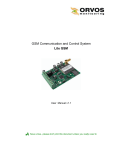
1
PT2060 Monitor
PT2060/43 R-RELAY Redundant-Relay
Module User Manual
Installation, Operation, Maintenance
ProvibTech, Inc.
11011 Brooklet Drive, Suite 360, Houston, Texas 77099, USA
Phone: +1-713-830-7601, Fax: +1-281-754-4972, Email: [email protected] , Web: www.provibtech.com
PT2060-43-USR-A-9
COPY RIGHT PROVIBTECH 2007
PT2060/43 R-RELAY Redundant-Relay Module
Contents
Receiving Inspection and Handling Guide......................................................................................................... 3
Inspection ................................................................................................................................................... 3
Handling and Storing Considerations......................................................................................................... 3
PT2060/43 Module Introduction ........................................................................................................................ 4
General Information.................................................................................................................................... 4
Function Table of Redundancy ........................................................................................................... 4
Channels of Redundant Relay Module Definition ............................................................................... 5
Module Description..................................................................................................................................... 5
Hardware............................................................................................................................................. 5
Software .............................................................................................................................................. 7
Specification ............................................................................................................................................... 7
Electrical.............................................................................................................................................. 7
Physical ............................................................................................................................................... 7
Environmental ..................................................................................................................................... 8
Module Configuration and Channel Setup ........................................................................................................ 9
Hardware Configuration ............................................................................................................................. 9
Module Configuration Setting ................................................................................................................... 10
Configuration Software General Operation....................................................................................... 10
Functions........................................................................................................................................... 13
Parameter Configuration ................................................................................................................... 13
Hardware Module Operation ........................................................................................................................... 16
Maintenance .................................................................................................................................................... 18
Instruction ................................................................................................................................................. 18
Periodic Maintenance............................................................................................................................... 18
Troubleshooting ............................................................................................................................................... 19
LED........................................................................................................................................................... 19
System Events List ................................................................................................................................... 19
Alarm Event List ....................................................................................................................................... 20
Exceptional Module Treatment................................................................................................................. 21
Ordering Information........................................................................................................................................ 22
Appendix.......................................................................................................................................................... 23
PT2060/43 Led Definition......................................................................................................................... 23
Definition of 43 LED .......................................................................................................................... 23
Definition of 53 Default LED.............................................................................................................. 23
Definition of 53 individual LED .......................................................................................................... 24
PT2060/43 Led and Relay Definition........................................................................................................ 24
Definition of 43 Relays ...................................................................................................................... 24
Definition of 53 Default Relays.......................................................................................................... 25
Definition of 53 individual Relays ...................................................................................................... 25
ProvibTech
Phone: +1-713-830-7601 Fax: +1-281-754-4972
2
[email protected] , www.provibtech.com
PT2060/43 R-RELAY Redundant-Relay Module
Receiving Inspection and Handling Guide
Inspection
Check the devices for possible damage that may have occurred from improper transport. Damages in transit
must be recorded on the transport documents. All claims for damages must be claimed without delay against
the shipper and before the installation.
Handling and Storing Considerations
PT2060 should be handled with care during unpacking and installation. Damage to PT2060 is typically
caused by rough handling, shock, or electrostatic discharge (ESD).
Be aware of the following precautions when unpacking and handling PT2060 Rack or any module.
9
Please have attention about the sharp corners/sides of the rack to avoid any of injuries during the
installation, transporting and un-installation.
9
All circuit boards and electronic modules associated with this rack contain components which are
susceptible to damage caused by electrostatic discharge. It should be necessary to discharge any static
electricity from yourself and your clothing before handling the rack.
9
Whenever the module is not installed in a system, always keep it in the protective antistatic bag.
ProvibTech
Phone: +1-713-830-7601 Fax: +1-281-754-4972
3
[email protected] , www.provibtech.com
PT2060/43 R-RELAY Redundant-Relay Module
PT2060/43 Module Introduction
General Information
When customer requires a highly reliable system, PT2060/43 R-REALY redundant relay
module(Figure1) is recommended. PT2060 system supports up to three PT2060/43 redundant
relay modules mounted in slot no.4, no.8, and no.12.They combine with modules in slots (1,2,3),
(5,6,7), (9,10,11) to compose a triple or dual redundant system.
PT2060/43 R-REALY redundant relay module includes two parts, one PT2060/43-Front module
(in two groups to form double redundancy) and PT2060/43-Back module. PT2060/43 R-REALY
Redundant relay module has eight relays on top as one group and another eight relays on bottom
as another group. These two groups of relays work identical. Their hardware is totally separated.
So the output of the redundant relay module is a standard dual redundant output.
PT2060/43 processes three alarms from the identical channels that monitoring one point. The
channels are located on the left three signal conditioning modules. The alarms, together with the
OK status of the three modules will be logically processed by PT2060/43. So it is a two out of three
logic, or a two out of two logic with dual redundant output.
With three PT2060/53 O-SPEED modules and a PT2060/90 POWER module, it can constitute an
over-speed protection system.
Especially, in the small PT2060 rack, the PT2060/43 redundant relay module of the only forth slot
combines with modules in slots (1,2,3) to compose a triple or dual redundant system.
Function Table of Redundancy
Normally three channels will be logically processed. Below is the truth table.
Notes: 1 stands for alarm, 0 stands for no alarm.
Number of channel in
alarm
Number of channel in no
alarm
Number of NOT OK
channel
Figure 1
Alarm
3
0
0
1
2
1
0
1
2
0
1
1
1
1
1
1
1
0
2
1
1
2
0
0
0
3
0
0
0
2
1
0
0
1
2
0
0
0
3
0
ProvibTech
Phone: +1-713-830-7601 Fax: +1-281-754-4972
4
[email protected] , www.provibtech.com
PT2060/43 R-RELAY Redundant-Relay Module
Channels of Redundant Relay Module Definition
Relay/LED
CH1
PT2060/43
PT2060/53
(Default type)
PT2060/53
(Individual type)
CHANNEL-1-ALT
NOT OK
(for 43 module)
CHANNEL-1-DNG
NOT OK
(for 43 module)
ALT
CH3
CHANNEL-2-ALT
DNG
SLOT1-DNG
CH4
CHANNEL-2-DNG
DNG
SLOT2-DNG
CH5
CHANNEL-3-ALT
ALT
SLOT3-DNG
CH6
CHANNEL-3-DNG
ALT
SLOT1-NOT OK
CH7
CHANNEL-4-ALT
NO USED
SLOT2-NOT OK
CH8
CHANNEL-4-DNG
NO USED
SLOT3-NOT OK
CH2
NOT OK
(for 43 module)
Comment: The two groups have the same definitions. The specific explanation refers to Appendix A.
Module Description
Hardware
PT2060/43 R-REALY redundant relay module consists of two parts, one PT2060/43-Front and PT2060/43Back. There are 16 red LEDs on Front Panel that indicates relay status. Two additional green LEDs indicate
the top and the bottom group relays OK status. There are there terminals on back panel for relay controlling
output.
ProvibTech
Phone: +1-713-830-7601 Fax: +1-281-754-4972
5
[email protected] , www.provibtech.com
PT2060/43 R-RELAY Redundant-Relay Module
PT2060/40
RELAY
OK/IO
CH1
CH2
CH3
LED status
indicators
of channels.
CH4
CH5
CH6
NC1
ARM
NO
NC2
ARM
NO
NC3
ARM
NO
NC4
ARM
NO
NC5
ARM
NO
NC6
CH7
CH8
OK/IO
CH9
CH10
CH11
CH12
CH13
CH14
CH15
CH16
ARM
NO
NC7
ARM
NO
NC8
ARM
NO
NC9
ARM
NO
NC10
ARM
NO
NC11
ARM
Terminals
to external
devices.
NO
NC12
ARM
NO
NC13
ARM
NO
NC14
ARM
NO
NC15
ARM
NO
NC16
ARM
NO
Figure 2 Front & back panel
LED on the front panel of relay module indicates the modules and channel statuses, as described below.
9 OK / IO LED indicate whether the module and relay channels are okay.
A steady OK / IO LED indicates that the module is working OK. If OK / IO LED flashes, the digital
communications between module and system is OK
9 If relay LED is on,
It means that PT2060/43 redundant relay logic is true.
ProvibTech
Phone: +1-713-830-7601 Fax: +1-281-754-4972
6
[email protected] , www.provibtech.com
PT2060/43 R-RELAY Redundant-Relay Module
Software
The PT2060 System Configuration software can be used to configure the PT2060/43 R-REALY redundant
relay module. Each relay can be independently configured.
Relay alarm can be defined as the following options to configure:
9 Latch, non-latching
9 Normally de-energized, normally energized
9 Bypass, non-Bypass
Specification
Electrical
Power supply:
Internally converted by the rack power supply module
8.0W total typical for this module
Signal input:
Through internal bus or direct connection
Relays:
Seal: Epoxy
Capacity:
5A/240V or 5A/30V, resistance load
Relay type:
SPDT * 2; 8 sets
Isolation:
1000V/DC
LEDs:
OK / IO: green
ALARM: red
Approvals:
CE;
CSA:
Non-incendive, class I, div.2, Grps.ABCD, T4@Ta= -40℃ to +75℃
Certificate Number: 2011996
Physical
Each module comes with two components, the PT2060/43-Front assembly and the PT2060/43-Back
assembly.
Dimension and Location:
241mm(9.5in)×24.5mm(0.96in)
ProvibTech
Phone: +1-713-830-7601 Fax: +1-281-754-4972
7
[email protected] , www.provibtech.com
PT2060/43 R-RELAY Redundant-Relay Module
For 19″ rack, they can be mounted in slot 4, 8, or slot 12.
For 12″ rack, they can be mounted only in slot 4.
Weight:
1.0kg (2.0 lbs).
Environmental
Temperature:
Operation: -20℃ to 65℃
Storage temperature: -40℃ to 85℃
Humidity:
95% non-condensing
ProvibTech
Phone: +1-713-830-7601 Fax: +1-281-754-4972
8
[email protected] , www.provibtech.com
PT2060/43 R-RELAY Redundant-Relay Module
Module Configuration and Channel Setup
PT2060/43 R-REALAY module will monitor status of the system, modules, and channels on the rack. It will
also monitor channel alarms and sensor OK status. The communication is via. ProvibTech’s proper digital
protocol. PT2060 adopts the PLC hardware structure. The communication is fast and reliable.
In this chapter, the description of the configuration setting is based on PT2060 System Configuration.
Hardware Configuration
Each PT2060/43 R-REALY redundant relay module occupies a slot in the rack. A standard 19″ rack can
contain up to three PT2060/43 REALAY modules. A valid communication connection should be established
before the normal operating of the system.
To configure PT2060/43, communication between PT2060-CFG software and PT2060/43 module has to be
established. This communication is normally setup via. PT2060/91, the system interface module. As Figure 3
shows, Computer will connect PT2060/91, the System Interface Module via the RS232 on the front panel or
RS485 or RS232 on the back panel. Please consult PT2060/91 SIM user manual for more details.
SYSTEM
INTERFACE
91 SIM
ETHERNET
RS485
POWER
NC1
ARM
NO
NC2
ARM
NO
NC3
ARM
NO
NC4
ARM
NO
NC5
ARM
NO
NC6
PWR
COM
SIG
SHD
PWR
COM
SIG
SHD
C
H
1
PWR
COM
SIG
SHD
PWR
COM
SIG
SHD
C
H
3
C
H
2
PWR
COM
SIG
SHD
PWR
COM
SIG
SHD
C
H
1
PWR
COM
SIG
SHD
PWR
COM
SIG
SHD
C
H
3
C
H
2
PWR
COM
SIG
SHD
PWR
COM
SIG
SHD
C
H
1
PWR
COM
SIG
SHD
PWR
COM
SIG
SHD
C
H
3
C
H
2
PWR
COM
SIG
SHD
PWR
COM
SIG
SHD
C
H
1
PWR
COM
SIG
SHD
PWR
COM
SIG
SHD
C
H
3
C
H
2
PWR
COM
SIG
SHD
PWR
COM
SIG
SHD
C
H
1
PWR
COM
SIG
SHD
PWR
COM
SIG
SHD
C
H
3
C
H
2
250V/4A
FUSE
Y
B
_
T
S
OK RELAY R
47-63 HZ
175-264 VAC
HIGH VOLTAGE
90 POWER
NC
ARM
NO
COM
TRIP_MLT
RS232
PH-REF2
COM
PWR
PH-REF1
COM
POWER
PWR
250V/4A
FUSE
RS485
6
4
47-63 HZ
175-264 VAC
HIGH VOLTAGE
90 POWER
ARM
NO
NC7
ARM
NO
NC8
ARM
NO
NC9
ARM
NO
NC10
ARM
NO
NC11
ARM
NO
NC12
ARM
NO
NC13
ARM
NO
NC14
ARM
NO
NC15
ARM
NO
NC16
ARM
NO
C
H
4
COM
OUT1
COM
OUT2
COM
OUT3
COM
OUT4
SHIELD
COM
OUT1
COM
OUT2
COM
OUT3
COM
OUT4
SHIELD
SHIELD
C
H
4
C
H
4
COM
OUT1
COM
OUT2
COM
OUT3
COM
OUT4
SHIELD
COM
OUT1
COM
OUT2
COM
OUT3
COM
OUT4
SHIELD
C
H
4
C
H
4
COM
OUT1
COM
OUT2
COM
OUT3
COM
OUT4
SHIELD
+
_
RS232 PORT
Figure 3
ProvibTech
Phone: +1-713-830-7601 Fax: +1-281-754-4972
9
[email protected] , www.provibtech.com
PT2060/43 R-RELAY Redundant-Relay Module
Module Configuration Setting
Configuration Software General Operation
PT2060 System Configure software is an important part of performing test and maintenance of PT2060. Via
the software, PT2060 parameters are configured and the running status is displayed. For more detailed
information, please refer to PT2060 System Configure software user manual.
The figure below is the main frame window of the software. There are seven main items in the window.
Figure 4
Menu item File relates to file operations such as open, save and save as of a configuration file. Also, the item
System Setup in it is used to alternate the system measurement unit. See the figure below.
Figure 5
Menu item Communication->Upload is used to upload all configuration parameters from the PT2060 rack
currently connected to the computer and Communication->Download is used to download all configuration
parameters to the currently connected PT2060 rack.
From Communication Setup, connection with PT2060 monitor can be established. Setup communication
parameters and click button Download to re-set the parameters for the PT2060 rack.
ProvibTech
Phone: +1-713-830-7601 Fax: +1-281-754-4972
10
[email protected] , www.provibtech.com
PT2060/43 R-RELAY Redundant-Relay Module
Figure 6
Figure 7
Menu item Rack relates to rack operations. Its sub items are listed below.
9 Rack Clock Setup
Configure system clock of the PT2060 rack.
9 Rack Reset
Reset all alarms of the PT2060 rack.
9 Signal Module Control
Operations related to alarm bypass and multiply alarms.
9 Self-Test
Let the rack go into self-test mode. This is useful for troubleshooting.
9 Factory Information
Operations related to factory information.
Customized Modbus Registers
Operations related to Modbus Registers of the rack.
9
Figure 8
Menu item Calibration contains two subs, User Calibration and Factory Calibration. PT2060/31 TEMP module
has no User Calibration.
ProvibTech
Phone: +1-713-830-7601 Fax: +1-281-754-4972
11
[email protected] , www.provibtech.com
PT2060/43 R-RELAY Redundant-Relay Module
Figure 9
Menu item Status/Event contains operations related to current status and alarm events (recent 500 records),
such as reading or deleting. Its sub item Real-Time Value And Status is used to display the messages of all
channels. Sub item Modbus Range Setup is used to set a coefficient to PT2060 in order to make it compatible
with other devices based on the standard Modbus.
Figure 10
Item Security is used for security consideration. Here you can enter different passwords for different
permissions. The Factory Password allows factory permission and is for the factory staff only. You can modify
the passwords here and set effective time for them. If the period is expired, password has to be reentered to
continue your working.
Figure 11
The item Help introduces detailed operation steps to the user. It is a quick way to become acquainted with the
software.
Figure 12
ProvibTech
Phone: +1-713-830-7601 Fax: +1-281-754-4972
12
[email protected] , www.provibtech.com
PT2060/43 R-RELAY Redundant-Relay Module
Functions
NOT OK
This indicates that fault has been detected by the associated R-REALY redundant relay Module channel. If
the Channel OK status goes not OK, then the system OK Relay on the Rack PT2060/91 SIM Module will be
driven not OK.
BYPASS
This indicates if any of the channels in PT2060/43 R-REALY redundant relay Module has been bypassed.
Any of the following conditions can cause the Relay Module to be bypassed:
9
9
9
The Relay Module is in configuration mode
A fatal error was found during self-test
Any active channel is bypassed
Latching relay
When this option is selected, the corresponding relay alarm channel will hold the alarm state until it receives a
rack reset or the relay is reconfigured.
Parameter Configuration
After having connected the host computer and the PT2060, the PT2060 System Configuration software can
be started. Click the button Upload and the messages of PT2060 will be uploaded to the software. Click the
button Config and enter the proper password, the PT2060 will be changed to configuration status.
Figure 13
In the configuration status, right click on the picture of the module you want to configure will open a configuration
window for that module, where all parameters can be edited.
Warning
PT2060 is unable to alarm and protect in configuration status!!!
ProvibTech
Phone: +1-713-830-7601 Fax: +1-281-754-4972
13
[email protected] , www.provibtech.com
PT2060/43 R-RELAY Redundant-Relay Module
Application Advisory
ProvibTech recommends strongly that the original configuration
setting must be uploaded and saved before performing any
modifications to PT2060/43 inner parameters.
Configuration Considerations
9
9
Add monitor modules to the rack configuration before configuring the Relay Module.
Generally, Bypassing relay channels is not recommended;
Bypass and Working Mode Configuration
Relay’s working mode
PT2060/43 R-REALY redundant relay module has two working mode, energized and non-energized. This
indicates how to set relay hardware switch for relay I/O module. Default mode is non-energized.
Relay bypass
Bypass is used to bypass or prohibit relative channels. If this is enabled, corresponding relays will be
prohibited from working. This is not recommended. After that, press “download” button to download the
configuration information. Uploading and verifying these configuring information are recommended. Figure
shown as follows:
Figure 14
ProvibTech
Phone: +1-713-830-7601 Fax: +1-281-754-4972
14
[email protected] , www.provibtech.com
PT2060/43 R-RELAY Redundant-Relay Module
Normal Energized
Configuration password should be enabled and enter the configuration model before configuring Relay
Energized mode, When enabled, relative channels Relay will keep normal energized ,the default is normal
non-energized .Setup relative relays. Then download the configuration. Press OK to finish the procedure.
Latch relay
Control password should be enabled before configuration Relay Latch mode, when enabled, relative channels
will keep alarm status till it receives a rack reset or is reconfigured. This function is used for monitors’ alarm
latching. Pressing system reset button will cancel the alarm. Setup relative relays. Then download the
configuration. Press OK to finish the procedure.
Channels’ Status
When PT2060 system is running normally, each relay channel status can be displayed in the real time value
and status interface. Detail information refers to software manual. See Channel Status Record below.
Figure 15
ProvibTech
Phone: +1-713-830-7601 Fax: +1-281-754-4972
15
[email protected] , www.provibtech.com
PT2060/43 R-RELAY Redundant-Relay Module
Hardware Module Operation
This section describes I/O modules with direct relation to redundant relay module and how to connect them.
PT2060/43 R-REALY redundant relay back IO module:
NC1
ARM
NO
NC2
ARM
NO
NC3
ARM
NO
NC4
ARM
NO
NC5
ARM
NO
NC6
ARM
NO
NC7
ARM
NO
NC8
ARM
NO
NC9
ARM
NO
NC10
ARM
NO
NC11
ARM
Terminals for
connecting
relay contacts
to external
devices.
NO
NC12
ARM
NO
NC13
ARM
NO
NC14
ARM
NO
NC15
ARM
NO
NC16
ARM
NO
Figure16
ProvibTech
Phone: +1-713-830-7601 Fax: +1-281-754-4972
16
[email protected] , www.provibtech.com
PT2060/43 R-RELAY Redundant-Relay Module
WARNING
High voltage may be present. Contact could cause shock,
burn, or death. Do not touch exposed wires or terminals.
Remove all power when working with the module.
To remove a terminal block from its base, loosen the screws attaching the terminal block to the base, grip the
block firmly and pull. Do not pull the block out by its wires because this could loosen or damage the wires or
connector.
NOTICE
Relay contacts categorize NC (normal close), NO (normal open) and ARM
(armature). NC and NO define the armature contact status. In this case, the relay
coil is not powered.
Normally Energized
Normally De-energized
No power/No alarm
With power/No alarm
With power/In alarm
Figure 17
ProvibTech
Phone: +1-713-830-7601 Fax: +1-281-754-4972
17
[email protected] , www.provibtech.com
PT2060/43 R-RELAY Redundant-Relay Module
Maintenance
Instruction
User should not repair components inside a PT2060/43 RELAY module. The maintenance described here
covers the test of the module and check whether it works properly. But if the module behaves abnormal, User
has to replace it by a new one.
9 Periodic maintenance
9 Tool preparations
9 Build of the maintenance environment
9 Configuration software operating
9 Module test
9 Exceptional module treatment
Periodic Maintenance
This maintenance interval is very important for the module maintenance. Usually, a yearly maintenance is
sufficient. If PT2060/43 RELAY module works in extraordinary circumstance, user should shorten the interval
according to the actual situation.
Extraordinary circumstance means that
9 PT2060 is used to monitor some critical equipment
9 PT2060 works in high temperature, high humidity, and corrosive environment
Besides, maintenance interval should be adjusted according to plant maintenance period.
Application Advisory
ProvibTech recommends strongly that the original configuration
setting must be uploaded and saved before performing any
modification to it and restore it after maintenance has been done!
ProvibTech
Phone: +1-713-830-7601 Fax: +1-281-754-4972
18
[email protected] , www.provibtech.com
PT2060/43 R-RELAY Redundant-Relay Module
Troubleshooting
This section describes how to use the LED, and System Event List to troubleshoot a problem with PT2060/43
RELAY module or the Output module.
LED
LED located on the front panel are OK / IO LED, Alarm LED. They indicate directly the PT2060/43 RELAY
module working status. If something abnormal, user could analyze it and solve some problems.
OK / IO GREEN LED
Flash:
All channels are ok. Digital communication is ok.
On without flash: All channels are ok. No digital communication. This means there are problems in
communication.
Off:
One or more channels are not ok.
ALARM RED LED
On:
Off:
One or more channels are in alert or danger.
All channels on the module are in normal status. No alarms engaged.
If ALARM RED LED does not work normally, it may be caused by this: the module is failed. Try these to solve
it: remount the module; reset it; check the probe and cable.
System Events List
The System event list of PT2060/43 RELAY module could be seen in the PT2060 System Configuration
software. This list contains the recent 500 events.
Click menu item Status/Event->System Event of the software to open a new window like the figure below.
ProvibTech
Phone: +1-713-830-7601 Fax: +1-281-754-4972
19
[email protected] , www.provibtech.com
PT2060/43 R-RELAY Redundant-Relay Module
Figure 18
Click the button Upload at left-bottom corner of the window to obtain the new System events. In the left area,
there is a list of upload time which is the time you perform an upload from PT2060 rack. Click one of these
items to get its detail event list in the right field. Event without channel number means it does not concern any
channel. By browsing this event list, you will be able to know what happened recently. It may help the user to
solve some problems. The right each list means below:
Rack no. : rack address.
Event no. : existed system event code.
Module no.: module code where the system event has occurred.
Channel no.: channel code where the system event has occurred.
Event Type: explaining the system event meaning.
Time: when does the system event happen.
If you could not solve the problem by yourself, please save these message for our service staff.
Alarm Event List
Like System event, the software deals with alarm event list in the same way. It also keeps 500 recent alarm
events.
Click menu item Status/Event->Alarm Event of the software to open a new window like the figure below.
ProvibTech
Phone: +1-713-830-7601 Fax: +1-281-754-4972
20
[email protected] , www.provibtech.com
PT2060/43 R-RELAY Redundant-Relay Module
Figure 19
Click the button Upload at left-bottom corner of the window to obtain the new Alarm events. In the left field,
there is a list of upload time which is the time you perform an upload from PT2060 rack. Click one of these
items to get its detail event list in the right field. By browsing this event list, you will be able to know what
happened recently. It may help you to solve your problem.
Each list meaning on the right is the same as system event list.
If you could not solve the problem by yourself, please save these message for our service staff.
Exceptional Module Treatment
If any problem is discovered in the above test, Please contact the closer ProvibTech office.
ProvibTech
Phone: +1-713-830-7601 Fax: +1-281-754-4972
21
[email protected] , www.provibtech.com
PT2060/43 R-RELAY Redundant-Relay Module
Ordering Information
Each PT2060/43 relay module consists of two boards, PT2060/43-Front and PT2060/43-Back.
PT2060/43-AX
AX: Back-panel IO module
A0: Basic IO module
Accessories
There are several accessories for selecting:
PT2060-004300: PT2060/43 Front panel
PT2060-004001: PT2060/40/43 Back panel
ProvibTech
Phone: +1-713-830-7601 Fax: +1-281-754-4972
22
[email protected] , www.provibtech.com
PT2060/43 R-RELAY Redundant-Relay Module
Appendix
PT2060/43 Led Definition
Definition of 43 LED
PT2060/43 R-RELAY Redundant-Relay module has two groups of LED, they have the following meaning
when it works in 43 mode.
NOTE: LOGIC_CHANNEL1 is that each first channel of three signal modules consists of being one logic
channel when PT2060/43 R-RELAY Redundant-Relay module combines redundant system with the other
three signal modules.
GREEN_ LED
OK / IO
CH1
RED_LED_1
LOGIC_CHANNEL1_ALT
CH2
RED_LED_2
LOGIC_CHANNEL1_DNG
CH3
RED_LED_3
LOGIC_CHANNEL2_ALT
CH4
RED_LED_4
LOGIC_CHANNEL2_DNG
CH5
RED_LED_5
LOGIC_CHANNEL3_ALT
CH6
RED_LED_6
LOGIC_CHANNEL3_DNG
CH7
RED_LED_7
LOGIC_CHANNEL4_ALT
CH8
RED_LED_8
LOGIC_CHANNEL4_DNG
GREEN_LED
OK / IO
CH9
RED_LED_9
LOGIC_CHANNEL1_ALT
CH1 0
RED_LED_10
LOGIC_CHANNEL1_DNG
CH1 1
RED_LED_11
LOGIC_CHANNEL2_ALT
CH1 2
RED_LED_12
LOGIC_CHANNEL2_DNG
CH13
RED_LED_13
LOGIC_CHANNEL3_ALT
CH1 4
RED_LED_14
LOGIC_CHANNEL3_DNG
CH15
RED_LED_15
LOGIC_CHANNEL4_ALT
CH16
RED_LED_16
LOGIC_CHANNEL4_DNG
Definition of 53 Default LED
PT2060/43 R-RELAY Redundant-Relay module has two groups of LED. They have the following meaning
when it works in 53 default mode.
GREEN_LED
OK / IO
CH1
RED_LED_1
NOT OK (for 43 module)
CH2
RED_LED_2
NOT OK (for 43 module)
CH3
RED_LED_3
LOGIC_CH1_DNG
CH4
RED_LED_4
LOGIC_CH1_DNG
CH5
RED_LED_5
LOGIC_CH1_ALT
CH6
RED_LED_6
LOGIC_CH1_ALT
CH7
RED_LED_7
No used
CH8
RED_LED_8
No used
ProvibTech
Phone: +1-713-830-7601 Fax: +1-281-754-4972
23
[email protected] , www.provibtech.com
PT2060/43 R-RELAY Redundant-Relay Module
CH9
CH10
CH11
CH12
CH13
CH1 4
CH15
CH16
GREEN_LED
RED_LED_9
RED_LED_10
RED_LED_11
RED_LED_12
RED_LED_13
RED_LED_14
RED_LED_15
RED_LED_16
OK / IO
NOT OK (for 43 module)
NOT OK (for 43 module)
LOGIC_CH1_DNG
LOGIC_CH1_DNG
LOGIC_CH1_ALT
LOGIC_CH1_ALT
No used
No used
Definition of 53 individual LED
PT2060/43 R-RELAY Redundant-Relay module has two groups of LED, they have the following meaning
when it works in 53 individual mode.
NOTE:
SLOT(n) is first channel of first signal module when PT2060/43 R-RELAY Redundant-Relay module
combines redundant system with the other three signal modules.
CH1
CH2
CH3
CH4
CH5
CH6
CH7
CH8
CH9
CH10
CH11
CH1 2
CH13
CH14
CH15
CH16
GREEN_LED
RED_LED_1
RED_LED_2
RED_LED_3
RED_LED_4
RED_LED_5
RED_LED_6
RED_LED_7
RED_LED_8
GREEN_LED
RED_LED_9
RED_LED_10
RED_LED_11
RED_LED_12
RED_LED_13
RED_LED_14
RED_LED_15
RED_LED_16
OK / IO
NOT OK(for 43 module)
LOGIC_CH1_ALT
SLOT(n)_DNG
SLOT(n+1) _DNG
SLOT(n+2) _DNG
SLOT(n)_NOT OK
SLOT(n+1) _NOT OK
SLOT(n+2) _NOT OK
OK / IO
NOT OK(for 43 module)
LOGIC_CH1_ALT
SLOT(n)_DNG
SLOT(n+1) _DNG
SLOT(n+2) _DNG
SLOT(n)_NOT OK
SLOT(n+1) _NOT OK
SLOT(n+2) _NOT OK
PT2060/43 Led and Relay Definition
Definition of 43 Relays
PT2060/43 R-RELAY Redundant-Relay module has two groups of relays, they have the following meaning
when it works in 43 mode.
ProvibTech
Phone: +1-713-830-7601 Fax: +1-281-754-4972
24
[email protected] , www.provibtech.com
PT2060/43 R-RELAY Redundant-Relay Module
RELAY _1
RELAY _2
RELAY _3
RELAY _4
RELAY _5
RELAY _6
RELAY _7
RELAY _8
RELAY _9
RELAY _10
RELAY _11
RELAY _12
RELAY _13
RELAY _14
RELAY _15
RELAY _16
LOGIC_CHANNEL1_ALT
LOGIC_CHANNEL1_DNG
LOGIC_CHANNEL2_ALT
LOGIC_CHANNEL2_DNG
LOGIC_CHANNEL3_ALT
LOGIC_CHANNEL3_DNG
LOGIC_CHANNEL4_ALT
LOGIC_CHANNEL4_DNG
LOGIC_CHANNEL1_ALT
LOGIC_CHANNEL1_DNG
LOGIC_CHANNEL2_ALT
LOGIC_CHANNEL2_DNG
LOGIC_CHANNEL3_ALT
LOGIC_CHANNEL3_DNG
LOGIC_CHANNEL4_ALT
LOGIC_CHANNEL4_DNG
Definition of 53 Default Relays
PT2060/53 R-RELAY Redundant-Relay module has two groups of relays, both have the following meaning
when it works in 53 default mode.
RELAY _1
RELAY _2
RELAY _3
RELAY _4
RELAY _5
RELAY _6
RELAY _7
RELAY _8
RELAY _9
RELAY _10
RELAY _11
RELAY _12
RELAY _13
RELAY _14
RELAY _15
RELAY _16
NOT OK (for 43 module)
NOT OK (for 43 module)
LOGIC_CH1_DNG
LOGIC_CH1_DNG
LOGIC_CH1_ALT
LOGIC_CH1_ALT
No used
No used
NOT OK (for 43 module)
NOT OK (for 43 module)
LOGIC_CH1_DNG
LOGIC_CH1_DNG
LOGIC_CH1_ALT
LOGIC_CH1_ALT
No used
No used
Definition of 53 individual Relays
PT2060/53 R-RELAY Redundant-Relay module has two groups of relays, both have the following meaning
when it works in 53 individual mode.
ProvibTech
Phone: +1-713-830-7601 Fax: +1-281-754-4972
25
[email protected] , www.provibtech.com
PT2060/43 R-RELAY Redundant-Relay Module
RELAY _1
RELAY _2
RELAY _3
RELAY _4
RELAY _5
RELAY _6
RELAY _7
RELAY _8
RELAY _9
RELAY _10
RELAY _11
RELAY _12
RELAY _13
RELAY _14
RELAY _15
RELAY _16
ProvibTech
NOT OK (for 43 module)
LOGIC_CH1_ALT
SLOT(n)_CH1_DNG
SLOT(n+1)_CH1 _DNG
SLOT(n+2)_CH1 _DNG
SLOT(n)_CH1_NOT OK
SLOT(n+1)_CH1_NOT OK
SLOT(n+2)_CH1_NOT OK
NOT OK
LOGIC_CH1_ALT
SLOT(n)_CH1_DNG
SLOT(n+1)_CH1_DNG
SLOT(n+2)_CH1_DNG
SLOT(n)_CH1_NOT OK
SLOT(n+1)_CH1_NOT OK
SLOT(n+2)_CH1_NOT OK
Phone: +1-713-830-7601 Fax: +1-281-754-4972
26
[email protected] , www.provibtech.com