1
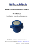
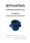
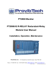
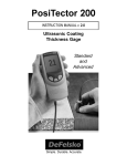
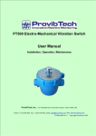
.
DM200 Dual-Channel A/V/D
Vibration Monitor
User Manual
Installation, Operation, Maintenance
ProvibTech, Inc.
11011 Brooklet Drive, Suite 300, Houston, Texas 77099, USA
Phone: +1-713-830-7601, Fax: +1-281-754-4972, Email: [email protected] , Web: www.provibtech.com
DM200-USR-E-C-3
COPY RIGHT PROVIBTECH 2012
DM200 Dual-Channel A/V/D Vibration Monitor
Content
Introduction ................................................................................................................................................................ 3 Specifications.............................................................................................................................................................. 3 Ordering Information.................................................................................................................................................. 4 Installation .................................................................................................................................................................. 6 Operation .................................................................................................................................................................. 16 Maintenance.............................................................................................................................................................. 18 2
ProvibTech
Phone: +1-713-830-7601 Fax: +1-281-754-4972 [email protected] , www.provibtech.com
2
DM200 Dual-Channel A/V/D Vibration Monitor
DM200 Dual-Channel A/V/D Vibration Monitor
Introduction
DM200 is a dual channel vibration monitor. It is
used to monitoring rotation machine’s absolute
vibration
with
acceleration,
velocity
or
displacement.
Features
9
9
9
9
9
9
9
9
9
9
Dual channels case vibration monitoring
with acceleration, velocity or displacement
Independent alert and danger dual relays on
each channel
Fully digital, long term stability
Condition monitoring with waveform and
spectrum
Modbus RTU
IP 65 or NEMA 4X environmental rating
Bright 4 digit LED display
Front panel buffered output
Wide range of power supply
Cost effective
Specifications
Electrical
Power Supply:
90-250VAC@ 500mA, 40-60Hz, or
22-30VDC@ 200mA
Frequency Response: (±3dB):
Standard:
2.0-3.0KHz;
Integration: 10-3.0KHz.
Low:
0.5-100Hz.
External Sensor:
Sensitivity: 100mV/g for accelerometer;
4.0mV/mm/s for velocity sensor;
40mV/mm/s or 4.0mV/um for low
frequency velocity/displacement
sensor.
Current Source: 4mA@24VDC
Buffered Output:
Original vibration, un-filtered;
Sensitivity/frequency: same as the sensor
specification.
Impedance :550Ω;
Maximum cable distance: 300m (1000ft).
Overall Vibration:
4-20mA source driving load resistance up to
500Ω.
System OK: Each channel output 4-20mA;
System Fault: Output<3.5mA.
Two Level Alarm:
Alarm setup (Normal/Set):
Scalable: 0-100%full scale;
Accuracy: ±0.1%.
Relays (Alert/Danger):
Hermetic Seal: Epoxy.
Capacity: 1A/220VAC or 1A/24VDC
resistive load.
Relay Type: SPDT.
Isolation:
1000VDC
Alarm Delay:
0-60 seconds.
Selectable with time interval of 1 second.
Alarm Multiply:
Switch Trip/Multi and COM, then set Double
Multiply or Triple Multiply by software, system
alarm value will increase a factor of 2 or 3.
RESET/BYPASS:
LOCALRESET;
REMOTE RESET/BYPASS: One shot
REST/BYP and COM
LED Machine Condition Indicator:
CH1 (Green) light on: Display the value of CH1;
CH2 (Green) light on: Display the value of CH2;
OK (Green) light on: Self-test passed, System
works OK;
ALARM (red) light on: Alarm indication.
Bus Communication (TX/RX):
All Setup and condition parameters can be
obtained from the bus connector.
Digital Condition Monitoring (Optional):
2
ProvibTech
Phone: +1-713-830-7601 Fax: +1-281-754-4972 [email protected] , www.provibtech.com
3
DM200 Dual-Channel A/V/D Vibration Monitor
Condition management software, such as
PCM360 can work with DM200 to collect, store,
and analyze machine running status via the
digital bus communication of the DM200.
9
9
9
9
9
Real-time dynamic waveform
Real-time spectrum (800 lines)
Real-time case XY vibration
Trend plot
Alarm list
Physical
Size: 170×90×118mm ( 6.69×3.54×4.64″)
Others as per drawing below:
(3.54inch)
DM 200
CH 1
ProvibTech
DUAL VIBRATION MONITOR
CH 2
OK/TX
OK/TX
ALARM
ALARM
-
SET
+
(6.69inch)
Front View
Side View
Weight:
1300 g.
Installation:
With Specific Holder.
Environmental
Temperature:
Operation:-25℃~+70℃;
Storage:-40℃~+100℃.
Humidity: 95%non-condensing.
(3.07inch)
(6.02inch)
Ordering Information
DM200-AXX-BX-CX-D1-EX-FX
AXX:Full Scale
A12: 0 ~ 5.0g pk
A13: 0 ~ 10g pk
A40*: 0 ~ 20mm/s rms
A41: 0 ~ 25 mm/s rms
A42: 0 ~ 50mm/s rms
A43: 0 ~ 100mm/s rms
A46: 0 ~ 1.0 ips rms
A47: 0 ~ 2.0 ips rms
A48: 0 ~ 4.0 ips rms
A50: 0 ~ 20mm/s pk
A51: 0 ~ 25 mm/s pk
A52: 0 ~ 50mm/s pk
A53: 0 ~ 100mm/s pk
A56: 0 ~ 1.0 ips pk
A57: 0 ~ 2.0 ips pk
A58: 0 ~ 4.0 ips pk
A60: 0 ~ 100um pk-pk
A61: 0 ~ 125um pk-pk
A62: 0 ~ 200um pk-pk
A63: 0 ~ 250um pk-pk
A64: 0 ~ 500um pk-pk
A66: 0 ~ 5mil pk-pk
A67: 0 ~ 10mil pk-pk
A68: 0 ~ 20mil pk-pk
BX: Sensor (not include)
B0*: TM0782A, TM0783A, or any ICP
Accelerometer with 100mV/g (A60-A68 not
applicable)
B1: TM0793V or any ICP Velocity Sensor with
4mV/mm/s (A12, 13 not applicable)
B2: TM079VD (A12, 13 not available)
BXXX: Seismic Sensor, Sensitivity = XXX
CX: Frequency Response
C0*: Normal Frequency (B2 not applicable)
C1: Low Frequency (B2 only)
DX: Environmental Rating (front panel)
D1*: IP65 or NEMA 4X
EX: Digital Communication
E0*: No digital communication
E1: With Modbus
E2: With Modbus and Digital Condition
Monitoring
FX: Power Supply
F0*: 110 VAC or 230 VAC
2
ProvibTech
Phone: +1-713-830-7601 Fax: +1-281-754-4972 [email protected] , www.provibtech.com
4
DM200 Dual-Channel A/V/D Vibration Monitor
F1: 24 VDC
* Factory default
Accessories
DM200-CFG-K
DM200 configuration and calibration software kit
includes:
9
9
DM200-CFG configuration and calibration
software CD
RS485-USB converter with cable
PCM-TCP: Modbus RTU-TCP Converter
TM0782A-K-M: Accelerometer Kit.
TM0783A-K-M: Accelerometer with Integral
Cable.
TM0793V-K-M: Velocity Sensor Kit.
TM079VD-V/H-K: Low Frequency Velocity/
Displacement Sensor.
TM0303: NEMA Housing.
TM0401: Barrier.
2
ProvibTech
Phone: +1-713-830-7601 Fax: +1-281-754-4972 [email protected] , www.provibtech.com
5
DM200 Dual-Channel A/V/D Vibration Monitor
Installation
Assembling Introduction
z
Introduction
DM200 Size: 170×90×118mm ( 6.69×3.54×4.64″)
.Installation in three situations: plate installation, rail mounting installation and installation with TM0303
waterproof case
z Installation method
(1)Plate preparation:
1. Prepare a plate with a hole to hold the monitor case, hole details as per drawing,
User need to make the hole by himself
Dimension
2. Locate the spacer like below (If you need the spacer, please indicate in your order information)
3. Locate the monitor into the plate hole, details as per pictures below:
2
ProvibTech
Phone: +1-713-830-7601 Fax: +1-281-754-4972 [email protected] , www.provibtech.com
6
DM200 Dual-Channel A/V/D Vibration Monitor
4. Fix the holder. Holder should be held tight into the hole of Transmitter case, as per pictures below.
5. Install the screw to fix the left side.
2
ProvibTech
Phone: +1-713-830-7601 Fax: +1-281-754-4972 [email protected] , www.provibtech.com
7
DM200 Dual-Channel A/V/D Vibration Monitor
6. Repeat 4 and 5, to install right side. Finally make the case and plate fixed tight. As the picture below:
(2)Rail Mounting Installation:
1. Purchase standard 35MM rail, cut into suitable length. Each DM200 requires two pieces.
2. Fix the two pieces of rail, we can do the fix somewhere you need with screw.
3. Make the rail edge and case holding tight, installation as per (1)4, 5 and 6.
2
ProvibTech
Phone: +1-713-830-7601 Fax: +1-281-754-4972 [email protected] , www.provibtech.com
8
DM200 Dual-Channel A/V/D Vibration Monitor
4. Installation over
(3)Installation with TM0303 waterproof case:
1. Refer to Plate Installation to fix DM200 in TM0303 case.
2
ProvibTech
Phone: +1-713-830-7601 Fax: +1-281-754-4972 [email protected] , www.provibtech.com
9
DM200 Dual-Channel A/V/D Vibration Monitor
2. Fix TM0303 case somewhere (with 4 thread hole) you want with 4 pieces M8 screw.
2
ProvibTech
Phone: +1-713-830-7601 Fax: +1-281-754-4972 [email protected] , www.provibtech.com
10
DM200 Dual-Channel A/V/D Vibration Monitor
A-4-20
B-COM
A-COM
B-BUF
A-BUF
COM
COM
B-P/A
A-P/A
B-S/B
A-S/B
Shield Wire
Red Wire
TRIP/MLTP
BUS+
COM
BUS-
RESET/BYP
Remote
Reset
Red Wire
White Wire
COM
B-AC
A-AC
B-A
A-A
B-AO
A-AO
B-DC
A-DC
B-D
A-D
B-DO
A-DO
TO
ALERT
(A)
TO
DANGER
(A)
TO
DANGER
(B)
TO
ALERT
(B)
Shield Wire
RS-485
TR+ TR-
Trip-Multiply
or phase
reference
input
White Wire
(-)
B-4-20
(-)
(+)
(+)
4-20mA(A)
4-20mA(B)
DM200 Field-wiring Diagram for TM0782A, TM0793V, TM079VD or other ICP sensor
L
N
POWER SUPPLY
90~250VAC
─ +
POWER SUPPLY
22~30VDC
DM200 Nonhazardous Area
Note:
9 If the DM200 has the digital condition monitoring function, the Trip/Multi and COM pins are used for
phase reference input. Moreover, the DM200 won’t provide Multiply Alarm function anymore, so you
should set Multiply Alarm property to “None” by DM200-CFG software.
2
ProvibTech
Phone: +1-713-830-7601 Fax: +1-281-754-4972 [email protected] , www.provibtech.com
11
A-4-20
B-COM
A-COM
Red Wire
A-BUF
COM
COM
B-P/A
A-P/A
B-S/B
A-S/B
TRIP/MLTP
BUS+
COM
BUS-
RESET/BYP
Remote
Reset
TO
TO
DANGER ALERT
(B)
(B)
Shield Wire
B-A
A-A
B-AO
A-AO
B-DC
A-DC
B-D
A-D
B-DO
A-DO
2 1
TO
DANGER
(A)
Red Wire
A-AC
TO
ALERT
(A)
3 4
Red Wire
White Wire
COM
B-AC
TM0401
(MTL787SP+)
Shield Wire
RS-485
TR+ TR-
Trip-Multiply
or phase
reference
input
White Wire
B-BUF
(-)
B-4-20
(-)
Shield Wire
1 2
(+)
(+)
4-20mA (A)
4-20mA(B)
DM200 Dual-Channel A/V/D Vibration Monitor
L
N
TM0401
(MTL787SP+)
4 3
Red Wire
Shield Wire
─ +
POWER SUPPLY
90~250VAC
POWER SUPPLY
22~30VDC
DM200 Hazardous Area
DM 200
CH 1
ProvibTech
DUAL VIBRATION MONITOR
CH 2
OK/TX
OK/TX
ALARM
ALARM
-
CH1 Buffered Output
SET
+
CH2 Buffered Output
DM200 Buffered Output
2
ProvibTech
Phone: +1-713-830-7601 Fax: +1-281-754-4972 [email protected] , www.provibtech.com
12
DM200 Dual-Channel A/V/D Vibration Monitor
System wiring diagram (configuration)
Channel1
amperemeter
Channel2
amperemeter
SHIELD
RED
WHITE
TRIPLE
B-4-20
A-4-20
B-COM
A-COM
B-BUF
A-BUF
COM
COM
B-P/A
A-P/A
B-S/B
A-S/B
TRIP/MLTP
BUS+
COM
BUS-
RESET/BYP
WHITE
COM
B-AC
REMOTE
RESET
SHIELD
RED
A-AC
B-A
A-A
B-AO
A-AO
B-DC
A-DC
B-D
A-D
B-DO
A-DO
B
TM0782A/
TM0793V
L
N
POWER SUPPLY
90 ~250VAC
TM0782A/
TM0793V
─ +
POWER SUPPLY
22 ~30VDC
T/R-
T/R-
T/R+
A
T/R+
USB<->RS485
Converter
Laptop computer
RS485<->RS232
Converter
Either of USB to RS485 and RS485 to RS232 can be
used
DM200 with USB-RS485 converter or RS232-RS485 converter
2
ProvibTech
Phone: +1-713-830-7601 Fax: +1-281-754-4972 [email protected] , www.provibtech.com
13
DM200 Dual-Channel A/V/D Vibration Monitor
Channel1
amperemeter
Channel2
amperemeter
B-4-20
A-4-20
B-COM
A-COM
B-BUF
A-BUF
COM
COM
B-P/A
A-P/A
B-S/B
A-S/B
SHIELD
RED
WHITE
TRIP/MLTP
BUS+
COM
BUS-
TRIPLE
RESET/BYP
WHITE
COM
B-AC
REMOTE
RESET
SHIELD
RED
A-AC
B-A
A-A
B-AO
A-AO
B-DC
A-DC
B-D
A-D
B-DO
A-DO
B
B
TM0782A/
TM0793V
BUSBUS+
BUSBUS+
BUSBUS+
L
N
POWER SUPPLY
90~ 250VAC
BUS-
TX+/422
BUS+
TX-/422
BUS-
RX+/422
BUS+
RX-/422
BUS-
D-/485/B
BUS+
D+/485-A
DTM96
A
TM0782A/
TM0793V
─ +
POWER SUPPLY
22~ 30VDC
RX/232
TX/232
Laptop computer
COM
24V(+)(2)
GND
USB<->RS232
Converter
24V(+)(1)
+
-
+24V
Power
DM200 with DTM96
2
ProvibTech
Phone: +1-713-830-7601 Fax: +1-281-754-4972 [email protected] , www.provibtech.com
14
DM200 Dual-Channel A/V/D Vibration Monitor
Channel1
amperemeter
Channel2
amperemeter
SHIELD
RED
WHITE
TRIPLE
B-4-20
A-4-20
B-COM
A-COM
B-BUF
A-BUF
COM
COM
B-P/A
A-P/A
B-S/B
A-S/B
TRIP/MLTP
BUS+
COM
BUS-
RESET/BYP
RED
WHITE
COM
B-AC
REMOTE
RESET
SHIELD
A-AC
B-A
A-A
B-AO
A-AO
B-DC
A-DC
B-D
A-D
B-DO
A-DO
B A
L
N
POWER SUPPLY
90~250VAC
TM0782A/
TM0793V
─ +
POWER SUPPLY
22~30VDC
V2+ 24
V2-
Power
Supply1
RS-422/485
GND
Data-(A)/RxD-(A)
TxD-(A)
V1+ 24
V1-
GND
Data+(B)/RxD+(B)
Dual power input
and relay output
To
Alarm
Power
Supply2
Shielded Ground
TxD+(B)
GND
RS-232
Laptop computer
Ethernet1 Ethernet2
PCM-TCP
SWITCH
DM200 with Modbus RTU-TCP converter
2
ProvibTech
Phone: +1-713-830-7601 Fax: +1-281-754-4972 [email protected] , www.provibtech.com
15
DM200 Dual-Channel A/V/D Vibration Monitor
Operation
DM200 Status Indicators
First Channel Setup:
LED CH1:
Green LED. Denotes that the value
of CH1 is being displayed.
LED CH2:
Green LED. Denotes that the value
of CH2 is being displayed.
LED OK/TX:
Green LED. Denotes that the
system has passed the Self-test
and is working good ; The LED will
flash when digital communications
are active.
Ch 1 Display Zero Calibration:
Connect the sensor to the first channel
terminal and make the sensor immobile.
Press SET. The first LED displays 1 and
last three LED display the current vibration
measured value, symbolizing entering
Display zero calibration status. If the
display value is not zero, press – until it
changes to zero.
LED ALARM: Red LED. Alarm indication.
DM200 Field Controls
Local reset:
Push the “SET” button on the
Front panel to reset the unit.
Remote Reset: One Shot the RST/BYP and COM
and Bypass
terminals to reset the system.
Switch the terminals and enable the
Bypass function (disable the
alarms).
Trip-Multiply:
Swith Trip/Multi and COM
Terminals will increase the alarm
set points a factor of 2 or 3 (Set
using the DM200-CFG software).
DM200 Field Adjustment
(Front Panel adjustment)
The DM200 alarm and danger set-points can be
field configured without configuration software
by using the following procedure.
9
9
Power up the system.
Connect a current meter to the 4-20mA
output terminal.
Enter The Setup & Operation Status:
Press the SET button for 3 seconds. The
display will show “11111”, symbolizing the
entrance to First Channel Setup status.
Ch 1 4-20mA Zero Calibration:
Connect a current meter to the first channel
4-20mA output terminal. Press SET again
to transfer to 4-20mA Zero Calibration
status. The first LED displays 1 and last
three LED display 4.00, symbolizing
entering Ch1 4-20mA zero calibration
status. Press + or - until the output value
changes to 4.0mA.
Ch 1 4-20mA Full scale setup:
Press SET again to transfer to 4-20mA Full
Scale Setup status. The first LED displays
1 and last three LED display 20.0,
symbolizing entering setup status. Press +
or - until output value changes to 20.0mA.
Ch 1 ALERT Point Setup:
Press SET again and to transfer to the
ALERT Point Setup status. The first LED
displays 1 and last three LED display the
last ALERT value. The current output will
now be a value between 4 and 20 that
corresponds to the desired setpoint. For
example, given a full scale of 0-1.0ips and a
desired Alarm setpoint of 0.5ips the current
output will need to be set to 12mA. Press +
or - until the output reaches the desired
setting.
Ch 1 DANGER Point Setup:
Press SET again to transfer to DANGER
Point Setup status. The first LED displays
1 and last three LED display the last
DANGER value. The current output will
now be a value between 4 and 20 that
corresponds to the desired setpoint. For
example, given a full scale of 0-1.0ips and a
desired Danger setpoint of 0.75ips the
current output will need to be set to 16mA.
Press + or - until the output reaches the
desired setting.
2
ProvibTech
Phone: +1-713-830-7601 Fax: +1-281-754-4972 [email protected] , www.provibtech.com
16
DM200 Dual-Channel A/V/D Vibration Monitor
Second Channel Setup:
Press SET again to enter Ch2 Setup. The
LEDs will display 22222.
Ch 2 Display Zero Calibration:
Connect the sensor to the second channel
terminal and make the sensor immobile.
Press SET. The first LED displays 2 and
last three LED display the current vibration
measured value, symbolizing entering
Display Zero Calibration status. If the
display value is not zero, press – until it
changes to zero.
Ch 2 4-20mA Zero Calibration:
Connect a current meter to the second
channel 4-20mA output terminal. Press
SET again to transfer to 4-20mA Zero
Calibration status. The first LED displays 2
and last three LED display 4.00,
symbolizing entering Ch2 4-20mA zero
calibration status. Press + or - until the
output value changes to 4.0mA.
Ch 2 4-20mA Full scale setup:
Press SET again to transfer to 4-20mA Full
Scale Setup status. The first LED displays
2 and last three LED displays 20.0,
symbolizing entering setup status. Press +
or - until the output value changes to
20.0mA.
Ch 2 ALERT point setup:
Press SET again to transfer to ALERT
Point Setup status. The first LED displays
2 and last three LED display the last
ALERT value. The current output will now
be a value between 4 and 20 that
corresponds to the desired setpoint. For
example, given a full scale of 0-1.0ips and a
desired Alarm setpoint of 0.5ips the current
output will need to be set to 12mA. Press +
or - until the output reaches the desired
setting.
Ch 2 DANGER Point Setup:
Press SET again and transfer to DANGER
Point Setup status. The first LED displays
2 and last three LED display the last
DANGER value. The current output will
now be a value between 4 and 20 that
corresponds to the desired setpoint. For
example, given a full scale of 0-1.0ips and a
desired Danger setpoint of 0.75ips the
current output will need to be set to 16mA.
Press + or - until the output reaches the
desired setting.
Exit setup:
Press SET again to exit setup status.
2
ProvibTech
Phone: +1-713-830-7601 Fax: +1-281-754-4972 [email protected] , www.provibtech.com
17
DM200 Dual-Channel A/V/D Vibration Monitor
Maintenance
DM200 Calibration Without Software
The DM200 can be configured with alarms
set-points without software. See section
DM200 Field Adjustment for details.
DM200 Modbus Protocol
The
DM200
supplies
Modbus
RTU
communications for system interface with any
upper level controller. The standard registers
are listed below. For further registry and
protocol information pelase contact your
Provibtech office.
DM200 Calibration With Software
The DM200-CFG software supplies additional
configuration parameters and calibration
functions to the customer. Please see the
software
manual
for
more
details
(DM200-CFG-USR).
DM200 Default Communication Setup
Baud Rate: 9600bit/s
Parity Bit: None
Stop Bit :2 bits
ID: 63
Modbus range :16384
DM200 Communication and Password Reset
Power off the DM200.
Press the + and – button at the same time and
then power on the DM200.
Hold down the + and - buttons for about 10
seconds until all 5 LEDs blink and display
66666.
After the above operations, the DM200
communication and password will be reset to:
Baud Rate: 9600bit/s
Parity Bit: None
Stop Bit :2 bits
ID: 63
Modbus range :16384
30501
30502
30503
30504
10139
CH1 Overall Vibration Level
CH1 Gap Voltage (in mV)
CH2 Overall Vibration Level
CH2 Gap Voltage (in mV)
CH1 Status Bit (read only)
Bit 0=0/1 Ok/ Not ok
Bit 1=0/1 Not Alert/ Alert
Bit 2=0/1 Not Danger/ Danger
Bit 3=0/1 Not Bypass/ Bypass
Bit 4=0/1 Not Trip Multiply/ Trip Multiply
10147 CH2 Status Bit (read only)
Bit 0=0/1 Ok/ Not ok
Bit 1=0/1 Not Alert/ Alert
Bit 2=0/1 Not Danger/ Danger
Bit 3=0/1 Not Bypass/ Bypass
Bit 4=0/1 Not Trip Multiply/ Trip Multiply
Note:The Overall Vibration Level is related to the full
scale range and Modbus range. For example, if the
Modbus range is 16384 and full scale range is 20
mm/s, then the current vibration measured value is 10
mm/s while the Modbus value is 8192. The Modbus
range could be set with an integer from 1 to 65535,
and the default is 16384.
2
ProvibTech
Phone: +1-713-830-7601 Fax: +1-281-754-4972 [email protected] , www.provibtech.com
18