1
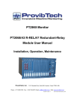
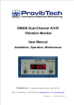
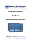
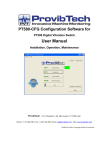
PT2060 Monitor
PT2060/53 O-SPEED Over-speed System
User Manual
Installation, Operation, Maintenance
ProvibTech, Inc.
11011 Brooklet Drive, Suite 300, Houston, Texas 77099, USA
Phone: +1-713-830-7601, Fax: +1-281-754-4972, Email: [email protected] , Web: www.provibtech.com
PT2060-53-USR-A-11
COPY RIGHT PROVIBTECH 2007
PT2060/53 O-SPEED Over-speed System
Contents
Receiving Inspection and Handling Guide......................................................................................................... 3
Inspection ................................................................................................................................................... 3
Handling and Storing Considerations......................................................................................................... 3
PT2060/53 Module Introduction ........................................................................................................................ 4
General Information.................................................................................................................................... 4
Module Description..................................................................................................................................... 6
Hardware............................................................................................................................................. 6
Software .............................................................................................................................................. 6
Specifications ............................................................................................................................................. 6
Electrical.............................................................................................................................................. 6
Environmental ..................................................................................................................................... 8
Physical ............................................................................................................................................... 8
Module Configuration and Channel Setup ........................................................................................................ 9
Hardware Configuration ............................................................................................................................. 9
Module Type, Channel Configuration Setting ............................................................................................ 9
Configuration Software General Operation......................................................................................... 9
PT2060/53 O-SPEED Module Function Description......................................................................... 12
Parameter Configuration ................................................................................................................... 13
Transducer List......................................................................................................................................... 19
Module Control and Real-time Monitoring................................................................................................ 20
Hardware Module Operation ........................................................................................................................... 22
Front, Back Panels and Functions ........................................................................................................... 22
Front Panel........................................................................................................................................ 22
Back Panel ........................................................................................................................................ 23
Field-wiring Diagram................................................................................................................................. 24
Module Maintenance ....................................................................................................................................... 27
Periodic Maintenance............................................................................................................................... 27
Preparations ............................................................................................................................................. 27
Tool Preparation................................................................................................................................ 27
Build of Maintenance Environment ................................................................................................... 28
Software Preparation ........................................................................................................................ 28
Module Testing ......................................................................................................................................... 29
Current Calibration ................................................................................................................................... 32
Exceptional Module Treatment................................................................................................................. 33
Troubleshooting ............................................................................................................................................... 34
LED........................................................................................................................................................... 34
Real-time Value and Status...................................................................................................................... 35
System Event List..................................................................................................................................... 35
Alarm Event List ....................................................................................................................................... 36
Exceptional Module Treatment................................................................................................................. 37
Additional Information ...................................................................................................................................... 38
Ordering Information ................................................................................................................................ 38
Optional Accessories................................................................................................................................ 38
Examination.............................................................................................................................................. 38
Factory Default Configuration................................................................................................................... 38
Appendix.......................................................................................................................................................... 39
Terminal for Proximity Probe.................................................................................................................... 39
Terminal for Magnetic Pickup................................................................................................................... 39
Bypass Terminal....................................................................................................................................... 39
Alarms Trip multiply Terminal................................................................................................................... 39
ProvibTech
Phone: +1-713-830-7601 Fax: +1-281-754-4972
2
[email protected] , www.provibtech.com
PT2060/53 O-SPEED Over-speed System
Receiving Inspection and Handling Guide
Inspection
Check the devices for possible damage that may have occurred from improper transport. Damages in transit
must be recorded on the transport documents. All claims for damages must be claimed without delay against
the shipper and before the installation.
Handling and Storing Considerations
PT2060 should be handled with care during unpacking and installation. Damage to PT2060 is typically
caused by rough handling, shock, or electrostatic discharge (ESD).
Be aware of the following precautions when unpacking and handling PT2060 Rack or any module.
9
Please have attention about the sharp corners/sides of the rack to avoid any of injuries during the
installation, transporting and un-installation.
9
All circuit boards and electronic modules associated with this rack contain components which are
susceptible to damage caused by electrostatic discharge. It should be necessary to discharge any static
electricity from yourself and your clothing before handling the rack.
9
Whenever the module is not installed in a system, always keep it in the protective antistatic bag.
ProvibTech
Phone: +1-713-830-7601 Fax: +1-281-754-4972
3
[email protected] , www.provibtech.com
PT2060/53 O-SPEED Over-speed System
PT2060/53 Module Introduction
General Information
ProvibTech’s PT2060/53 O-SPEED over-speed System provides a highly reliable, triple
redundant over-speed protection system. PT2060/53 O-SPEED over-speed module can accept
speed from both proximity probe and magnetic pickup signal input. It can output the following
measurements:
9 Over-speed protection
The following function only for channel 3 and channel 4.
9 Radial vibration: monitoring shaft vibration, single or dual XY (2 channels)
9 Axial/ Thrust position: monitoring shaft thrust position, with 5mm, 8mm, and 11 mm
proximity probes (2 channels)
9 Eccentricity (1 channel)
9 Differential expansion (2 channels)
9 Low-frequency vibration (2 channels)
9 Speed output (1 channel)
9 Zero speed and speed (1 channel)
9 Reverse rotational protection output (1 channel)
Voting
PT2060/53 O-SPEED Over-speed System supports two out of three voting.
Redundancy Requirement
To reach the maximum system reliability, PT2060/53 requires redundant power supplies. Alarms
Trip multiply PT2060/53 modules are required. With three over-speed modules, system will
perform two out of three redundant logic.
Figure 1
To maximum system reliability, ProvibTech highly recommend customer utilize three over-speed modules and
one redundant alarm module as an over-speed protection system.
Alarm Option
PT2060/53 of O-SPEED System will output alarms to drive the redundant PT2060/43 module. The redundant
alarm module will perform redundant logic or simply deliver the individual alarms from each channel to
up-level control system for logic output.
The main task for PT2060/53 O-SPEED module is to process the incoming signal, compare it with the alarm
set-point and output the appropriate status information. The status information will be routed to PT2060
internal bus for other modules to sharing. It is also directly output to the redundant alarm module for process.
ProvibTech
Phone: +1-713-830-7601 Fax: +1-281-754-4972
4
[email protected] , www.provibtech.com
PT2060/53 O-SPEED Over-speed System
A PT2060/53 O-SPEED System consists of three PT2060/53 O-SPEED modules and one PT2060/43
R-RELAY Redundant-Relay module. A standard 19″ PT2060 rack can contain three such systems at most,
slot 1-4, slot 5-8 and slot 9-12 are the defined slots to hold the sub-systems. PT2060/43 R-RELAY modules
can be mounted in slot 4, slot 8 or slot 12 only. A standard 12″ PT2060 rack can contain one such system, slot
1-4. In the case, PT2060/43 R-RELAY module is mounted in slot 4. Three PT2060/53 O-SPEED modules
must be installed in three adjacent slots. For example, three PT2060/53 O-SPEED modules installed in slot
1-3 and a PT2060/43 R-RELAY module installed in slot 4 constitute an over-speed system.
A PT2060/53 O-SPEED module contains three channels: the first channel is an over-speed protection
channel; channel 3 and 4 can be used as two PT2060/10 channels. Any PT2060/10 mode can be configured
into these two channels.
For PT2060/53 O-SPEED Over-speed System, the PT2060/43 R-RELAY Redundant-Relay module works
only with the first channel of the PT2060/53 module. The rest of the channels will have no effect to the relay
module.
In PT2060/53 O-SPEED Over-speed System, PT2060/53 O-SPEED modules measure machine rotation
speed and provide real-time value, GAP voltage, and 4-20mA current to users. It also provides alarm status
and OK status to PT2060/43 R-RELAY Redundant-Relay module of the system. The PT2060/43 R-RELAY
module receives the messages from PT2060/53 modules and conducts Boolean calculation of these
messages and output calculated result trough the LEDs, and the relays. Working in the over-speed system,
PT2060/43 R-RELAY Redundant-Relay module can run in Default 53 Mode or Individual Mode. For more
details, please refer to PT2060/43 R-RELAY Redundant-Relay Module User Manual.
Warning
When the 3rd and the 4th channel of a PT2060/53 O-SPEED module
are used as PT2060/10 module, its operation and configuration are
the same as the normal PT2060/10 PROX module. Please refer to
PT2060/10 PROX manual for more information.
This manual describes the application of PT2060/53 O-SPEED
module in O-SPEED system mainly.
The system should be installed in the rack and configured by software PT2060 System Configuration. PT2060
System Configuration configures parameters for PT2060/53 O-SPEED System. It will also display various
messages including real-time value, GAP voltage and alarm status, alarm event and system event.
ProvibTech
Phone: +1-713-830-7601 Fax: +1-281-754-4972
5
[email protected] , www.provibtech.com
PT2060/53 O-SPEED Over-speed System
Module Description
Hardware
The hardware of PT2060/53 O-SPEED Over-speed System consists of up to three PT2060/53 O-SPEED
modules and one PT2060/43 R-RELAY Redundant-Relay module.
PT2060/53 O-SPEED module has status indication on board. There are three LEDs that display different
status of the monitored channels on front panel. There are four BUFs of the four channels and 4-20mA
current output port on the back panel. This manual mainly describes the application of PT2060/53 O-SPEED
module in PT2060/53 O-SPEED Over-speed System. The functions of PT2060/43 R-RELAY
Redundant-Relay module are described in PT2060/43 R-RELAY Redundant-Relay Module User Manual.
Software
PT2060/53 O-SPEED Over-speed System needs PT2060 System Configuration to cooperate with it.
Relevant introduction of the software is described in PT2060/10 PROX Proximity Module User Manual and
PT2060 system Configuration User Manual. PT2060/43 R-RELAY Redundant-Relay module relevant
introduction of the software is described in PT2060/43 R-RELAY Redundant-Relay Module User Manual and
PT2060 system Configuration User Manual.
Specifications
Electrical
PT2060/53 O-SPEED Over-speed System includes three PT2060/53 O-SPEED modules and a PT2060/43
R-RELAY Redundant-Relay module.
PT2060/53 O-SPEED Over-speed Module
Power supply:
Internally converted by the rack power supply module
8.0W total typically for each module
Signal Input:
Input impedance:
> 20KΩ
Input voltage range:
+10 to -24VDC
Input frequency:
The PT2060/53 module will support 1 - 255 events per revolution with a maximum full scale range of
60000 rpm and a maximum input frequency of 10 kHz.
Start at 1RPM (0.0167Hz) for proximity probes
Start at 200RPM (3.3Hz) for magnetic pickup
ProvibTech
Phone: +1-713-830-7601 Fax: +1-281-754-4972
6
[email protected] , www.provibtech.com
PT2060/53 O-SPEED Over-speed System
Sensors:
Proximity probes
Magnetic pickups
Overall in 4-20mA Output:
Maximum distance:
300m (1000ft)
Proportional to monitor full-scale; each channel has its own overall speed output. The short of the
4-20mA will not affect system performance.
Maximum Load:
300Ω
Accuracy:
+/-0.1RPM (< 100RPM)
+/-1.0RPM (> 100 and < 10,000RPM)
0.01% (> 10,000 and < 60,000RPM)
Threshold:
Auto:
> 1.0 V pk-pk
Manual:
> 0.5 V pk-pk. Trigger level can be programmed from -17VDC to -3VDC
Hysteresis:
0.5 - 2.5 V user selectable
Alarm Time Delay:
< 30ms for frequency (pulses) over 300Hz
Rack Space:
Require four slots for an over speed protection system.
Buffered Output:
On the front panel, each channel has one BNC connector. The output is the unfiltered raw signal.
Output impedance:
550Ω
Maximum distance:
300m (1000ft)
Proximity Transducer Power:
-24VDC, current limited. Less than 50mA on each channel
Alarm:
Alarm set-point:
Each channel has single alarm set-point which can be field adjusted from 0 to 100% FS.
Set-point accuracy:
+/-1 RPM
LED Indicators:
OK / IO: green
Alarms: red
Bypass: red
Approvals:
CE;
ProvibTech
Phone: +1-713-830-7601 Fax: +1-281-754-4972
7
[email protected] , www.provibtech.com
PT2060/53 O-SPEED Over-speed System
CSA:
Non-incendive, class I, div.2, Grps.ABCD, T4@Ta= -40℃ to +75℃
Certificate Number: 2011996
PT2060/43 R-RELAY Redundant-Relay Module
Please refer to PT2060/43 R-RELAY Redundant-Relay Module User Manual.
Environmental
Temperature:
Operation: -20℃ to +65℃
Storage: -40℃ to +85℃
Humidity:
95% non-condensing
Physical
PT2060/53 O-SPEED Over-speed Module
Each module comes with two components: the front panel assembly and the back panel assembly.
Dimensions:
241mm (9.5in) X 24.5mm (0.96in)
For 19″ rack, mounts in any one of the following slots:
1-3, 5-7, 9-11.
For 12″ rack, mounts in slot 1-3.
Weight:
1.0 kg (2.0 lbs)
PT2060/43 R-RELAY Redundant-Relay Module
Please refer to PT2060/43 R-RELAY Redundant-Relay Module User Manual.
ProvibTech
Phone: +1-713-830-7601 Fax: +1-281-754-4972
8
[email protected] , www.provibtech.com
PT2060/53 O-SPEED Over-speed System
Module Configuration and Channel Setup
In a PT2060/53 O-SPEED Over-speed System, PT2060/53 O-SPEED module can accept either proximity
probe or magnetic pickup signal input. Monitor function has to be configured by the software PT2060 System
Configuration before using. The following description of software configuration setting is based on PT2060
System Configuration software.
Hardware Configuration
Each PT2060/53 O-SPEED Over-speed System occupies four slots. A standard 19″ rack can contain three
such sub-systems at most. A 12″ rack can contain one such sub-systems only.
To configure PT2060/53, communication between PT2060-CFG software and PT2060/53 module has to be
established. This communication is normally setup via PT2060/91, the system interface module. As Figure 2
shows, Computer will connects PT2060/91, the System Interface Module via the RS232 on the front panel or
RS485 or RS232 on the back panel. Please consult PT1060/91 SIM User Manual for more details.
SYSTEM
INTERFACE
91 SIM
ETHERNET
RS485
POWER
NC1
ARM
NO
NC2
ARM
NO
NC3
ARM
NO
NC4
ARM
NO
NC5
ARM
NO
NC6
PWR
COM
SIG
SHD
PWR
COM
SIG
SHD
C
H
1
PWR
COM
SIG
SHD
PWR
COM
SIG
SHD
C
H
3
C
H
2
PWR
COM
SIG
SHD
PWR
COM
SIG
SHD
C
H
1
PWR
COM
SIG
SHD
PWR
COM
SIG
SHD
C
H
3
C
H
2
PWR
COM
SIG
SHD
PWR
COM
SIG
SHD
C
H
1
PWR
COM
SIG
SHD
PWR
COM
SIG
SHD
C
H
3
C
H
2
PWR
COM
SIG
SHD
PWR
COM
SIG
SHD
C
H
1
PWR
COM
SIG
SHD
PWR
COM
SIG
SHD
C
H
3
C
H
2
PWR
COM
SIG
SHD
PWR
COM
SIG
SHD
C
H
1
PWR
COM
SIG
SHD
PWR
COM
SIG
SHD
C
H
3
C
H
2
250V/4A
FUSE
Y
B
_
T
S
OK RELAY R
47-63 HZ
175-264 VAC
HIGH VOLTAGE
90 POWER
NC
ARM
NO
COM
TRIP_MLT
RS232
PH-REF2
COM
PWR
PH-REF1
COM
POWER
PWR
250V/4A
FUSE
RS485
47-63 HZ
175-264 VAC
HIGH VOLTAGE
90 POWER
6
4
_
ARM
NO
NC7
ARM
NO
NC8
ARM
NO
NC9
ARM
NO
NC10
ARM
NO
NC11
ARM
NO
NC12
ARM
NO
NC13
ARM
NO
NC14
ARM
NO
NC15
ARM
NO
NC16
ARM
NO
COM
OUT1
COM
OUT2
COM
OUT3
COM
OUT4
SHIELD
SHIELD
C
H
4
COM
OUT1
COM
OUT2
COM
OUT3
COM
OUT4
SHIELD
C
H
4
C
H
4
COM
OUT1
COM
OUT2
COM
OUT3
COM
OUT4
SHIELD
COM
OUT1
COM
OUT2
COM
OUT3
COM
OUT4
SHIELD
C
H
4
C
H
4
COM
OUT1
COM
OUT2
COM
OUT3
COM
OUT4
SHIELD
+
RS232 PORT
Figure 2
Module Type, Channel Configuration Setting
Configuration Software General Operation
PT2060 System Configuration software is an important part of configuring, controlling and maintaining the
PT2060 system. The software is used to configure PT2060 internal parameters and display PT2060 running
status. Refer to PT2060 System Configure User Manual for its details.
ProvibTech
Phone: +1-713-830-7601 Fax: +1-281-754-4972
9
[email protected] , www.provibtech.com
PT2060/53 O-SPEED Over-speed System
The figure below is the main frame window of PT2060 System Configuration, where are seven main menu
items.
Figure 3
Menu item File relates to file operations such as open, save and save as of a configuration file. Also, the item
System Setup in it is used to alternate the system measurement unit. See the figure below.
Figure 4
Menu item Communication->Upload is used to upload all messages of the PT2060 rack currently connected
to the computer and Communication->Download is used to download all messages configured in the
computer to the currently connected PT2060 rack.
From Communication Setup, connection with PT2060 monitor can be established. Setup communication
parameters and click button Download to re-set the parameters for the PT2060 rack.
Figure 5
ProvibTech
Phone: +1-713-830-7601 Fax: +1-281-754-4972
10
[email protected] , www.provibtech.com
PT2060/53 O-SPEED Over-speed System
Figure 6
Menu item Rack relates to rack operations. Its sub items are listed below.
Rack Clock Setup: Setup system clock for the PT2060 rack.
Rack Reset: Reset all alarms of the PT2060 rack.
Factory Information: Operations related to factory information.
Configurable Modbus Registers: Operations related to Modbus Registers of the rack.
Signal Module Control: Operations related to alarm bypass and Alarms Trip multiply alarms.
Self-Test: To make the rack go into self-test mode. This is useful for troubleshooting.
Figure 7
Menu item Calibration contains two subs, User Calibration and Factory Calibration. Users could perform User
calibration only.
Figure 8
Menu item Status/Event contains operations related to current status and alarm history (recent 500 records),
such as reading or deleting. Its sub item Real-time Value and Status is used to display the messages of all
channels. Sub item Modbus Range Setup is used to set a coefficient to PT2060 in order to make it compatible
with other devices based on the standard Modbus.
ProvibTech
Phone: +1-713-830-7601 Fax: +1-281-754-4972
11
[email protected] , www.provibtech.com
PT2060/53 O-SPEED Over-speed System
Figure 9
Item Security is used for security consideration. Here you can enter different passwords for different
permissions. The Factory Password allows factory permission and is for the factory staff only. However, you
can modify the passwords here and set effective time for them. If the period is expired, password should be
reentered to go on working.
Figure 10
The item Help introduces detailed operation steps to the user. It is a quick way to become acquainted with the
software.
Figure 11
PT2060/53 O-SPEED Module Function Description
GAP not OK
When the GAP voltage is above the Upper OK limit and below the Lower OK limit, the OK / IO LED on the
front panel is off. The GAP not OK status in the window Real-Time Value and Status is true. If alarms are true
and those alarms have been configured as latching, after GAP becomes not OK, they retain true.
Once a channel has gone not OK status, the output current of this channel is 3.0 ±0.16mA.
Notes: Usually, Alert type can be configured as either alert or gap alarm. When PT2060/53 module is used for
PT2060/53 O-SPEED Over-speed System, it does not support GAP alarm.
ProvibTech
Phone: +1-713-830-7601 Fax: +1-281-754-4972
12
[email protected] , www.provibtech.com
PT2060/53 O-SPEED Over-speed System
Bypass
This indicates when the module has bypassed alarming. Both digital port and hardware port can trigger
bypass mode. When it is hardware bypassed, the Bypass LED on the front panel comes on. When it is
software bypassed, the LED does not come on. No matter what is the case, the measured value will not be
affected except the alarms on the module. Bypass is valid for Alert type and GAP type alarms. Bypass has
higher priority than alarm latching does.
The system is not bypassed by default.
A channel bypass status may result from the following conditions:
9 PT2060/53 O-SPEED module has never been configured
9 PT2060/53 O-SPEED module is in configuration mode
9 Channel of PT2060/53 O-SPEED module has an invalid configuration
9 PT2060/53 O-SPEED module is in power up self-test
9 Fatal error found during self-test
9 Alarming is bypassed via PT2060 System Configuration software
9 Channel of PT2060/53 O-SPEED module is disable
Alarms Trip multiply
In PT2060/53 O-SPEED Over-speed System, PT2060/53 O-SPEED module channels working in speed
measuring mode does not support Alarms Trip multiply alarm.
Channel Disable
If PT2060/53 O-SPEED module is configured into channel disable status, The GAP not OK is False. Alarms
are False. GAP value is 10.0V and real-time value is full scale low.
Parameter Configuration
After the host computer and the PT2060 are connected. Start PT2060-CFG configuration software. In the
main window of the software, click the button Upload to upload all PT2060 messages.
Click the picture of the module you want to configure to open a configuration window for that module, where
all parameters can be edited. Download or upload the configuration information according to the need. It
needs configuration password when first download or. The default password is 1234.
ProvibTech
Phone: +1-713-830-7601 Fax: +1-281-754-4972
13
[email protected] , www.provibtech.com
PT2060/53 O-SPEED Over-speed System
Figure 12
Warning
PT2060 is unable to alarm and protect in configuration status!!!
Warning
ProvibTech recommends strongly that the original configuration
setting must be uploaded and saved before performing any
modifications to PT2060/53 inner parameters.
In PT2060/53 O-SPEED Over-speed System, the configuration procedure of PT2060/43 R-RELAY
Redundant-Relay module is referred to PT2060/43 R-RELAY Redundant-Relay Module User Manual.
PT2060/53 O-SPEED modules support over-speed measure. Proximity probes or magnetic pickups should
be mounted in radial direction.
PT2060/53 O-SPEED modules measure the shaft rotation speed, provide measured message to the user,
and give alarm messages to the PT2060/43 R-RELAY Redundant-Relay module to implement the function of
over-speed protection.
While working in the PT2060/53 O-SPEED Over-speed System, only the first channel of PT2060/53
O-SPEED module is in use. Its configuration procedure is the same as of PT2060/10 Speed.
Configuration Considerations
Consider the following items before configuring a PT2060/53 O-SPEED Over-speed System:
1. All modules in the Over-speed system must have identical configurations.
2. A three-module Over-speed protection System is the most reliable.
3. When a full-scale range is modified, the set-points associated with this proportional value should be
re-adjusted.
4. PT2060/53 Over-speed protection System provides fast response relays for shutdown purposes. Do not
use any other PT2060 system relays for Over-speed shutdown.
5. PT2060/53 Over-speed protection System is only one of several components in an Over-speed
Shutdown System. All components must be verified for proper operation.
ProvibTech
Phone: +1-713-830-7601 Fax: +1-281-754-4972
14
[email protected] , www.provibtech.com
PT2060/53 O-SPEED Over-speed System
Over-speed Parameter Setting
Typical full scale cam be set to 3000, 3600, 6000, 10000, 60000RPM.
Channel Type
Over-speed
Transducer Type
PT2060/53 O-SPEED modules can interface with many kinds of transducers:
TM0180/5m
TM0180/9m
TM0105/5m
TM0105/9m
TM0110/5m
TM0110/9m
3300/8mm/5m, 5mm/5m
3300/8mm/9m, 5mm/9m
7200/8mm/5m, 5mm/5m
7200/8mm /9m, 5mm/9m
3300/11mm/5m
3300/11mm/9m
7200/11mm/5m
7200/11mm/9m
Other 8mm Proximity probe transducer
Other 5mm Proximity probe transducer
Other 11mm Proximity probe transducer
Magnetic pickup
Transducer Sensitivity
This is the most important parameter in monitoring process. The value is related to the transducer type. When
the transducer type is anyone of proximity probes, this value is set by the system and also can be modified
manually. This value is typically expressed as millivolt per unit (for example mV/mil for displacement). Default
value is 8mv/μm. When the transducer type is magnetic pickup, this item invalidates.
Alert Time Delay, Danger Time Delay
PT2060/53 O-SPEED Over-speed System doesn’t support alarm time delay.
Teeth Per Cycle
Teeth number on the gear. The number of input pulses per shaft revolution when observing an integral
multi-event signal source, such as a gear. The Events per Revolution may be specified as a number between
1 and 255 with four decimals . Default is 60 . User could set it according to the actual value in the field. For
example, if there are 24 teeth on the gear, teeth per cycle can be set to 23.9998 to slightly adjust the
rotation speed according to the need in the field.
Hysteresis Voltage
The voltage level above and below the threshold value which is required to "trigger" the input signal from the
transducer. The larger the hysteresis, the greater the immunity to noise on the input signal. When the input
signal passes the threshold voltage plus 1/2 of the Hysteresis voltage, the signal goes high. When the input
signal returns to the threshold voltage minus 1/2 of the Hysteresis voltage, the signal goes low. The default
ProvibTech
Phone: +1-713-830-7601 Fax: +1-281-754-4972
15
[email protected] , www.provibtech.com
PT2060/53 O-SPEED Over-speed System
value is 1V and user could modify it between 0.5-2.5V.
Trigger Voltage
The Trigger Value is the nominal voltage that the Hysteresis is centered about. The system gives a default
value. When Manual Threshold is selected, user could modify it manually or by clicking the button Adjust to let
the system get it automatically. Default is -10V.
Full Scale High, Full Scale Low
These determine the low limit and high limit of full scale. Full scale low is set to 0 by default. Full scale high
can be set by user as per actual situation. After these are set, the alarm hysteresis is determined. Alarm
hysteresis default is 10RPM constantly.
Notes: All set-points have an Alarm Hysteresis value. The Alarm Hysteresis band for an over set-point is
below the set-point and the Alarm Hysteresis band for an under set-point is above the set-point. For example,
if an over-speed set-point is set at 3,000 rpm, the hysteresis is 10RPM. The module would enter over-speed
alarm at 3,000 rpm but would not go out of alarm until the speed has fallen to 2,990 rpm.
Measurement Type
User could choose desired type from the drop list. Default is NA.
Measurement Unit
From the menu item File-System Setup a window, like the following figure, can be opened where user could
alternate the measurement unit. For over-speed measuring, it is RPM constantly.
Figure 13
Alert Type
Alert type means that PT2060/53 O-SPEED modules give out alarm message, when the measured value
exceeds or equals to alert and/or danger set-point assigned by PT2060 System Configuration. Every channel
of a monitor is capable of producing an Alert indication. These indications can be used in relay alarm drive
logic which is configured in the Relay.
When a PT2060/53 O-SPEED module works in PT2060/53 O-SPEED Over-speed System, it does not
support GAP alarm.
Channel Enabled
Channel Enabled lets you control whether or not the monitor channel is used. (If the box is checked (√), the
channel is used). Its default status is checked. User could modify it as need.
Alarm Latching
Causes the PT2060/53 O-SPEED module to retain an alarm status after the alarm condition has gone away.
The latching alarm mode allows you to determine if an alarm set-point has been exceeded or equaled since
the last rack reset. The rack reset contact or reset button on the PT2060/91 SIM module will reset all latched
alarms in the PT2060 rack if the current proportional value is less than the set-point value. You can also reset
the rack by using the PT2060 System Configuration software. Non-latching alarm causes the PT2060 monitor
to remove an alarm status after the alarm condition has gone away. The Event list for the monitor will provide
ProvibTech
Phone: +1-713-830-7601 Fax: +1-281-754-4972
16
[email protected] , www.provibtech.com
PT2060/53 O-SPEED Over-speed System
information about faulted transducers even if non-latching is selected. The default status is latched. User
could modify it.
Set Point
This is set for PT2060/53 O-SPEED modules’ alarm threshold. There are two levels of alert alarm. It can be
set to some certain percentage of full scale. Danger High is set to 75% and Alert High is set to 50% by default.
PT2060/53 O-SPEED modules in PT2060/53 O-SPEED Over-speed System do not support GAP alarm.
The GAP OK voltage range is related to the transducer type. When the transducer type is anyone of proximity
probes, this value is set by the system and also can be modified manually. The default settings are -24V and
-1V for GAP High and GAP Low respectively. When the transducer type is magnetic pickup, this item
invalidates.
Notes: Timed OK Channel Defeat, an option that prevents a channel from returning to an OK status until that
channel's transducer has remained in an OK state for the specified period of time. The time is set to 15
seconds. The time protects against false trips caused by intermittent transducers.
Threshold Type
The threshold options are Auto and Manual.
The threshold type is related to the transducer type. When the transducer type is anyone of proximity probes,
there are two choices, Auto and Manual. If the expected average running speed of the machine is less than
200 RPM, Manual threshold is suggested. When the transducer type is magnetic pickup, the default value is
Auto. The value can’t be modified manually.
Auto: The trigger threshold is automatically set to a value that is midway between the most positive peak and
the most negative peak of the input signal. This value tracks any changes in the input signal. Auto threshold
requires minimum signal amplitude of 1Vpp and minimum frequency of 0.0167 Hz.
Manual: The trigger threshold is set by the user to any value in the range of -8V to -14V. Manual threshold
requires that the minimum signal amplitude would be 500 millivolt with peak to peak.
Signal Polarity
Notch
An output pulse, produced for use by the modules that is triggered by the leading edge of a
negative-going pulse in the input signal. If a magnetic pickup is used, set Notch/Projection setting to Notch.
Projection
An output pulse, produced for use by the modules that is triggered by the leading edge of a positive-going
pulse in the input signal.
Peak Value
The maximum speed recorded by the PT2060/53 since the last peak value reset occurred. Click the drop
down list Peak Value Setup of menu status/Event to open Peak value window where peak value is present,
see figure 14 and 15.
Figure 14
ProvibTech
Phone: +1-713-830-7601 Fax: +1-281-754-4972
17
[email protected] , www.provibtech.com
PT2060/53 O-SPEED Over-speed System
PT2060/53 retains the peak value even after loss of module power. Click the the Reset button in configuration
software as the figure 15 shows, the Peak value will be reset to the present speed. Clicking the Reset button
can reset the peak values of the current corresponding slots and channels, while Reset All can reset the peak
values of all the speed type channels.
Figure 15
The following figure is an example of configuration.
Figure 16
ProvibTech
Phone: +1-713-830-7601 Fax: +1-281-754-4972
18
[email protected] , www.provibtech.com
PT2060/53 O-SPEED Over-speed System
Transducer List
The transducers PT2060/53 O-SPEED modules can be connected with:
Transducer input
Proximity Transducer
Magnetic pickup
ProvibTech
Module output
TM0180/5m
TM0180/9m
TM0105/5m
TM0105/9m
TM0110/5m
TM0110/9m
3300/8mm/5m, 5mm/5m
3300/8mm/9m, 5mm/9m
7200/8mm/5m, 5mm/5m
7200/8mm /9m, 5mm/9m
3300/11mm/5m
3300/11mm/9m
7200/11mm/5m
7200/11mm/9m
Other 8mm Proximity probe transducer
Other 5mm Proximity probe transducer
Other 11mm Proximity probe transducer
Over-speed
TM0605
Phone: +1-713-830-7601 Fax: +1-281-754-4972
19
[email protected] , www.provibtech.com
PT2060/53 O-SPEED Over-speed System
Module Control and Real-time Monitoring
PT2060/53 O-SPEED Over-speed System can measure rotation speed and give out high speed alarm via the
PT2060 System Configuration software. The description in this section is based on PT2060 System
Configuration software. For more detailed information, please refer to PT2060 System Configuration software
user manual.
Figure 17
Calibration, control, and maintenance of PT2060/53 O-SPEED module are performed with PT2060 System
Configuration software which is shown in above figure.
When PT2060 is in RUN state, from menu item Status/Event->Real-Time Value and Status->List open the
real-time monitoring window, as shown in the following figure.
Figure 18
In this window Real-time value, GAP value, alarm message are shown. Rack number, slot number, channel
number are seen at a glance. Besides, PT2060/53 O-SPEED modules can save various history events and
working status including alarm events, system events, channel status records, module status records, and
rack status records. Refer to section Troubleshooting.
PT2060/53 O-SPEED modules support alarm bypass, self-test functions. Alarm bypass is segregated into
software bypass and hardware bypass. Self-test is implemented through software control. In the PT2060/53
O-SPEED Over-speed System, PT2060/53 O-SPEED module channels, which is set to measuring speed,
ProvibTech
Phone: +1-713-830-7601 Fax: +1-281-754-4972
20
[email protected] , www.provibtech.com
PT2060/53 O-SPEED Over-speed System
does not support Alarms Trip multiply alarm. Working in other type of systems, it behaves the same as
PT2060/10 PROX module. See section PT2060/10 PROX module maintenance.
In PT2060/53 O-SPEED Over-speed System, PT2060/43 R-RELAY Redundant-Relay module should be
configured to “53 Default type” or “53 Individual type”. The procedure of configuration is referred to PT2060/43
R-RELAY Redundant-Relay Module User Manual.
ProvibTech
Phone: +1-713-830-7601 Fax: +1-281-754-4972
21
[email protected] , www.provibtech.com
PT2060/53 O-SPEED Over-speed System
Hardware Module Operation
Besides the software monitoring, PT2060/53 O-SPEED module hardware can directly provide some
messages of monitored equipment.
There are four BUF on the front panel and four current output ports on the back panel corresponding to the
four channels. This enhanced the versatility of the module. User could acquire desired signals from these
ports in the field. In PT2060/53 O-SPEED over-speed system, only the first BUF is used on PT2060/53
module.
Front, Back Panels and Functions
Front Panel
PT2060/53
O-SPEED
Figure 19
ProvibTech
Phone: +1-713-830-7601 Fax: +1-281-754-4972
22
[email protected] , www.provibtech.com
PT2060/53 O-SPEED Over-speed System
1. OK / IO LED
2. Alarm LED
3. Bypass LED
4. Buffered output
The output is raw unfiltered sensor signal to portable data collector.
5. Channel label
Customer is able to mark channels on the label in the field. Label can be marked by removing the front plastic
cover with a flat screw driver.
Back Panel
PWR
COM
SIG
SHD
PWR
COM
SIG
SHD
C
H
1
PWR
COM
SIG
SHD
PWR
COM
SIG
SHD
C
H
3
C
H
2
C
H
4
COM
OUT1
COM
OUT2
COM
OUT3
COM
OUT4
SHIELD
Figure 20
ProvibTech
Phone: +1-713-830-7601 Fax: +1-281-754-4972
23
[email protected] , www.provibtech.com
PT2060/53 O-SPEED Over-speed System
1. Signal port
The arrow is pointing the port which the channel 1 receives the signal (PT2060/53 module in the over-speed
system has only a channel).
2. 4-20mA output
Be proportional to the full scale, standard 4-20mA output. Connect with PLC or DCS.
Field-wiring Diagram
Field-wiring Diagram for all 5mm, 8mm and 11mm Probe Systems
2
8
1
0
M
T
C
H
1
PWR
COM
SIG
SHD
PWR
COM
SIG
SHD
C
H
3
POW(-24V)
COM
COM
SIG
ProvibTech
PWR
COM
SIG
SHD
PWR
COM
SIG
SHD
5mm/8mm Driver
SENSITIVITY:
8mV/um
200mV/mil
ProvibTech
C
H
2
C
H
4
COM
OUT1
COM
OUT2
COM
OUT3
COM
OUT4
SHIELD
Figure 21
ProvibTech
Phone: +1-713-830-7601 Fax: +1-281-754-4972
24
[email protected] , www.provibtech.com
PT2060/53 O-SPEED Over-speed System
Field-wiring Diagram for Magnetic Pickup Systems
PWR
COM
SIG
SHD
PWR
COM
SIG
SHD
C
H
1
PWR
COM
SIG
SHD
PWR
COM
SIG
SHD
C
H
3
White
Red
Shield
C
H
2
C
H
4
COM
OUT1
COM
OUT2
COM
OUT3
COM
OUT4
SHIELD
Figure 22
ProvibTech
Phone: +1-713-830-7601 Fax: +1-281-754-4972
25
[email protected] , www.provibtech.com
PT2060/53 O-SPEED Over-speed System
Field-wiring Diagram for Hazardous Area Application
With TM0412 as the barrier. For other barriers, please consult ProvibTech for tech support.
PWR
COM
SIG
SHD
PWR
COM
SIG
SHD
C
H
1
C
H
2
2
8
1
0
M
T
COM
COM
SIG
PWR
COM
SIG
SHD
PWR
COM
SIG
SHD
PROVIBTECH
POW(-24V)
5mm/8mm Driver
SENSITIVITY:
8mV/um
200mV/mil
PROVIBTECH
C
H
3
C
H
4
COM
OUT1
COM
OUT2
COM
OUT3
COM
OUT4
SHIELD
Figure 23
ProvibTech
Phone: +1-713-830-7601 Fax: +1-281-754-4972
26
[email protected] , www.provibtech.com
PT2060/53 O-SPEED Over-speed System
Module Maintenance
The maintenance of PT2060/53 O-SPEED Over-speed System includes two parts: PT2060/53 O-SPEED
module and PT2060/43 R-RELAY module. The former is described in this section and the latter is referred to
PT2060/43 R-RELAY Redundant-Relay Module User Manual.
Components inside a PT2060/53 O-SPEED module can not be repaired in the field. The maintenance
mentioned here means to check channel working status and determine whether it is in good condition. If the
linearity of some channels is not perfect, user could perform current calibration. If other faults are discovered,
please substitute for it with another spare part.
It is described how to check channel working status and how to calibrate output current in several sections.
9 Periodic maintenance
9 Tool preparation
9 Build of maintenance environment
9 Software operation
9 Module check
9 Current calibration
9 Exceptional module treatment
Periodic Maintenance
The time interval is very important for PT2060 maintenance. Generally, a yearly maintenance is sufficient. If
the equipment is used in an extraordinary circumstance, user should shorten the maintenance interval
according to the situation in the field.
Extraordinary circumstance means that
9 PT2060 is used to monitor some critical equipment
9 PT2060 works in high temperature, high humidity, and high corrosive environment
Besides, the maintenance interval should be adjusted according to the present result.
Preparations
Tool Preparation
The following tools are needed for PT2060/53 maintenance:
9 One Personal Computer
9 Two digital multi-meters for voltage measuring and current measuring
9 Signal generator
9 Oscilloscope
9 Some terminals
ProvibTech
Phone: +1-713-830-7601 Fax: +1-281-754-4972
27
[email protected] , www.provibtech.com
PT2060/53 O-SPEED Over-speed System
Build of Maintenance Environment
Follow these steps to build maintenance environment.
1. Make test terminals
Refer to Appendix for the procedure.
2. Make bypass terminals
Refer to appendix for the procedure.
3. Install PT2060 System Configuration software in a PC.
4. Connect the PT2060 to a PC using a communication cable.
5. Save the configuration setting of PT2060 to maintain to a file. Power it off, demount it from the equipment,
and move it to a workbench.
Application Advisory
ProvibTech recommends strongly that the original configuration
setting must be uploaded and saved before performing any
modification to it and restore it after maintenance has been done!
6. Get a signal generator set, and the oscilloscope ready.
7. Get two multimeters ready.
Software Preparation
You should be familiar with these functions:
9 Upload, download, save configuration parameters
9 Enable/disable channels and alarms latching
9 Bypass channels’ latching
9 Observe real-time value and status
On powering on and open the configuration software, the system uploads configuration parameters
automatically. You could also click the button Upload in the main frame window of the software to get all of the
configuration parameters and click the button Download to save them to the machine, after you have done
your modifications.
Click on the picture of PT2060/53 O-SPEED module to open PT2060/53 O-SPEED Module Configuration
window. At the right-up corner, there are items Channel enable and alarm latching. They are checked by
default.
Figure 24
ProvibTech
Phone: +1-713-830-7601 Fax: +1-281-754-4972
28
[email protected] , www.provibtech.com
PT2060/53 O-SPEED Over-speed System
From menu item “Rack->Signal Module Control” open the status control window, where slot number and
alarm set-point multiplication and bypass status are specified. Click the button Download to save it to
PT2060/53 O-SPEED module. The PT2060/53 O-SPEED module has no relation to alarm set-point
multiplication function, when it works in PT2060/53 O-SPEED Over-speed System.
Figure 25
Module Testing
When PT2060/53 O-SPEED module works in the PT2060/53 O-SPEED Over-speed System, it is only the first
channel that needs to be tested. When it works as other modules, the channel 3 and 4 are also need to be
test. For the latter testing, refer to the relevant section of PT2060/10 PROX Proximity Module User Manual.
Warning
High voltage! Contact could cause shock, burns, or death. Do not
touch exposed wires or terminals.
Application Alert
Tests will exceed alarm set-point levels causing alarms to activate.
This could result in a relay contact state change.
Application Alert
Disconnecting field wiring will cause a not OK condition!
1. System construction
If transducer type is anyone of proximity probes, take one proximity terminal. Plug the terminal into the first
channel of PT2060/53 back panel. Connect the red pen of an ampere meter to OUT pin of the current output
ProvibTech
Phone: +1-713-830-7601 Fax: +1-281-754-4972
29
[email protected] , www.provibtech.com
PT2060/53 O-SPEED Over-speed System
port and connect the black pen to GND pin on that port. Set the ampere meter to measure direct current. Feed
a signal to the channel through the positive pin of the electrolytic capacitor (220μF/50V) of the terminal.
Connect an oscilloscope to the BUF of the first channel.
If transducer type is magnetic pickup, take one magnetic terminal. Plug the terminal into the first channel of
PT2060/53 back panel. Connect the red pen of an ampere meter to OUT pin of the current output port and
connect the black pen to GND pin on that port. Set the ampere meter to measure direct current. Feed a signal
to the terminal. Connect an oscilloscope to the BUF of the first channel.
Turn on the PC and invoke the configuration software.
2. Test of powering on
On powering, OK / IO LED and Alarm LED should be on for 3s or so that indicates that the channel is
operating correctly.
3. Test of communication
Click the button Upload to obtain the parameters and save them in a safe place. If the upload failed, check
whether PC and PT2060 are set correctly and connected reliably.
4. Test of parameter setting
Click the picture of the tested module in the PT2060 System Configuration software main frame window to
open its configuration window where you could make some modifications. After that, you could download it
and re-upload it again to compare whether they are changed correctly.
5. Test of OK status
Disable PT2060/53 O-SPEED module’s channel 3 and 4.
If transducer type is one of proximity probes, tune the variable resistor (10kOhm) of the terminal plugged in
the first channel. Observe OK / IO LED status (it flashes only when all enabled channel are OK). When the
variable resistor is out of the assigned OK range, the OK / IO LED will go off. At this time, the output current is
3.0 ±0. 16mA.
If transducer type is magnetic pickup, the OK / IO LED is always on.
6. Test of linearity
According to the configured full scale and frequency in the field, provide a signal to the first channel using a
generator set. Check the output current to see whether it suffices the linearity requirement. If it is not perfect,
you can perform recalibration:
Percentage of full scale
0%
25%
50%
75%
100%
4~20mA (mA)
4.00±0.16
8.00±0.16
12.00±0.16
16.00±0.16
20.00±0.16
Notes: The magnitude of the input signal is 8V. Change the frequency as per the full scale. If the current full
scale is 0-6000RPM, number of teeth is 1, then the frequency should be in the range 0-100Hz.
7. Test of alarm
Disable the PT2060/53 O-SPEED module’s channel 3 and 4. Provide a signal to the first channel. Observe
the change of the Alarm LED, when the signal exceed or equal to any set-point and check the status in the
Real-time Value and Status window.
If the channel is not alarm latched, the alarm status will be reset after the input signal is removed. Otherwise, it
can be reset only by pressing the button RESET (or clicking menu item RACK->Rack Reset Setup). Check
the status in the Real-time Value and Status window. This part has also relation to alarm hysteresis.
8. Test of BUF
If necessary, users can perform BUF testing.
Tune the signal generator and monitor the BUF output with an oscilloscope which should be conformable with
ProvibTech
Phone: +1-713-830-7601 Fax: +1-281-754-4972
30
[email protected] , www.provibtech.com
PT2060/53 O-SPEED Over-speed System
the input one.
If transducer type is one of proximity probes, adjust the variable resistor to make it outputs a voltage of about
-10V and check the BUF output noise which should be less than 50mV.
If transducer type is magnetic pickup, check the BUF directly, the output noise should be less than 50mV.
This figure shows how to connect an oscilloscope to the BUF.
Figure 26
9. Test of software bypass
Checking the Channel Bypass switch will cause the module to indicate a "bypass" status but can not
illuminate the module bypass LED. Set Alert bypass and/or danger bypass for the tested channel and adjust
the input signal. When the signal reaches the magnitude corresponding to alarm threshold, the machine does
not give alarm signal, i.e. it is prohibited.
10. Test of hardware bypass
Provide a signal to make the system alarm. Plug in a bypass terminal into the socket on the back panel of
PT2060/91 SIM module. Bypass LED of the PT2060/53 O-SPEED module should be on and Alarm LED
should be off. The alarm status in Real-time Value and Status window disapear. Unplug the terminal and the
system goes on to alarm.
11. Test of voltage
Power supply is critical for PT2060/53 O-SPEED module to work properly. Measure the voltages of the
channels as per the figure below. They should be about -24V.
PWR
COM
SIG
SHD
PWR
COM
SIG
SHD
ProvibTech
C
H
1
C
H
2
Phone: +1-713-830-7601 Fax: +1-281-754-4972
31
[email protected] , www.provibtech.com
PT2060/53 O-SPEED Over-speed System
Figure 27
12. Test of redundant power
Provide channel 1 with a signal correspond to 50% of full scale. the output current should be 12+0.16mA.
Demount the lower power module and observe the output current whether it is stable. Remount the lower
power module and demount the upper power module and observe the output current.
Current Calibration
Users should not repair the components inside PT2060/53 O-SPEED modules. However, if some channels’
linearity is not satisfied after the testing, user can perform current calibration.
1. Connect the red pen of an ampere meter to OUT pin of the current output port; connect the black pen to
COM pin of that port.
2. Click menu item Calibration->User Calibration and enter password to open calibration window. See the
following figure. Select the slot number and channel number to be calibrated.
Figure 28
3. The whole procedure is implemented in the 4-20mA Calibration.
Click the button Full-scale low(Zero) Calibration to open the zero calibration window(figure 29). Follow the
steps showed in the window to perform calibration. First, click the button Start Calibration in step1, then read
the output current value from multimeter, after it settled down. Enter this value (three significant decimal digits)
in the text area in step2 . After that, click the button Full-scale low Calibration in step3 to download. Wait till
the multimeter outputs a right value. Click Exit to exit the zero calibration.
Figure 29
4. Click the button Full-scale high Calibration. Click OK button in the WARNING window(figure 30). Enter
YES in the Warning dialogue (figure 31) and click OK to open the calibration window(figure 32). Follow the
steps showed in the window to implement calibration. First, click the button Start Calibration in step1, then
ProvibTech
Phone: +1-713-830-7601 Fax: +1-281-754-4972
32
[email protected] , www.provibtech.com
PT2060/53 O-SPEED Over-speed System
read the output current value from multimeter, after it settled down. Enter this value (three significant decimal
digits) in the text area in step2. After that, click the button Full-scale high Calibration in step3 to download.
Wait till the multimeter outputs a right value. Click Exit to exit the high calibration.
Figure 30
Figure 31
Figure 32
5. Click the button Exit to go back to the RUN state. You could optionally do linearity test again to check the
calibrating result. If you does not satisfy, you could redo it.
Exceptional Module Treatment
Some exceptions may be discovered through the testing mentioned above. Except the linearity problem which
could be solved by recalibrating, users sould treat it in no case. Please substitute it by a spare part and
contact ProvibTech office.
ProvibTech
Phone: +1-713-830-7601 Fax: +1-281-754-4972
33
[email protected] , www.provibtech.com
PT2060/53 O-SPEED Over-speed System
Troubleshooting
PT2060/53 O-SPEED Over-speed System Troubleshooting consists of two parts: PT2060/53 O-SPEED
module Troubleshooting and PT2060/43 R-RELAY Redundant-Relay module Troubleshooting.
Troubleshooting relative to PT2060/43 R-RELAY modules is described in PT2060/43 R-RELAY
Redundant-Relay Module User Manual.
This section describes how to solve the problems in operation and analyze the status from the LED, Real-time
Value and Status, system event list, and alarm event list.
LED
There are OK / IO LED, Alarm LED, and Bypass LED on the front panel. They directly reflect the status of
PT2060/53 O-SPEED modules. If something abnormal happened, users could make a simple judgment.
OK / IO LED
Flash: All enabled channel are okay. Digital communication is ok.
On without flash: All enabled channels are ok. No digital communication. This means the PT2060/53
O-SPEED module has a problem with communication.
Off:
One or more channels are not ok.
If OK / IO green LED is off, the reason may be: some of enabled channels have GAP alarms; the connection
to transducers has broken; the proximity transducers are damaged; module is damaged. If the first reason
caused the problem, there is a 15s delay before the module changes from NOT OK status to OK status.
Try these to solve the problems: adjust transducers’ position to make the GAP value normalized; remount the
module; reset; check probes and connection cable.
Alarm LED
On:
One or more channels have alarms. When alarm type is Alert, the alarms can be either alert or
danger or both. When alarm type is GAP, the alarms can be either GAP or danger.
Off:
All channels on the module are in normal status. No alarms engaged.
If Alarm red LED does not work, it may be caused by that: the module is failed; transducers are broken. Try
these to solve the problem: remount the module; reset; check probes and connection cable.
Bypass LED
On:
PT2060 system is in hardware Bypass mode. All alarms on this module are inhibited from alarming
(no alarms will be engaged). PT2060/53 O-SPEED module’s real-time values and current outputs are not
affected.
Off:
Abnormal operation mode.
ProvibTech
Phone: +1-713-830-7601 Fax: +1-281-754-4972
34
[email protected] , www.provibtech.com
PT2060/53 O-SPEED Over-speed System
If Bypass red LED does not work, it may be caused by that: the PT2060/53 O-SPEED module fails. In this
case, please contact ProvibTech office.
Real-time Value and Status
From Real-time Value and Status interface, you may acquire something useful.
Figure 33
Alert
False: When alarm type is Alert, it means there is no Alert alarm. When alarm type is GAP, it means there is
no GAP alarm.
True:
When alarm type is Alert, it means there is an Alert alarm. When alarm type is GAP, it means there is
a GAP alarm.
Danger
False:
True:
There is no Danger alarm, in despite of the alarm type.
There is a Danger alarm, in despite of the alarm type.
GAP not OK
False: The channel is in okay status.
True:
The channel is in GAP not OK status. The reason may be that: the transducers’ GAP voltage is out
of range; some transducers are broken; the connection cable is not reliable. If the first reason caused the
problem, there is a 15s delay before the module changes from GAP not OK status to OK status.
System Event List
PT2060/53 O-SPEED modules’ system event list will be displayed in the software PT2060 System
Configuration. It lists 500 recent events.
Select Status/Event->System Event from the main menu; go into this interface as shown below.
ProvibTech
Phone: +1-713-830-7601 Fax: +1-281-754-4972
35
[email protected] , www.provibtech.com
PT2060/53 O-SPEED Over-speed System
Figure 34
Click the button Upload at left-bottom corner of the window to obtain the new system events. In the left area,
there is a list of upload time which is the time you perform an upload from PT2060 rack. Click one of these
items to get its detail event list in the right field. Event without channel number means it does not concern any
channel. Take the highlighted line in figure above for example, the PT2060/53 O-SPEED module in slot 6
entered run model sometime. By browsing this event list, you will be able to know what happened recently. It
may help the user to solve some problems.
If you could not solve the problem by yourself, please save all information for ProvibTech service staff.
Alarm Event List
Like system event, the software deals with alarm event list in the same way. It also keeps 500 recent alarm
events.
Click menu item Status/Event->Alarm Event of the software to open a new window like the figure below.
ProvibTech
Phone: +1-713-830-7601 Fax: +1-281-754-4972
36
[email protected] , www.provibtech.com
PT2060/53 O-SPEED Over-speed System
Figure 35
Click the button Upload at left-bottom corner of the window to obtain the new Alarm events. In the left field,
there is a list of upload time which is the time you perform an upload from PT2060 rack. Click one of these
items to get its detail event list in the right field. By browsing this event list, you will be able to know what
happened recently. It may help you to solve your problem.
If you could not solve the problem by yourself, please save these messages for ProvibTech service staff.
Exceptional Module Treatment
If you find PT2060/53 O-SPEED modules in problem from the above analyses, please contact ProvibTech
office.
ProvibTech
Phone: +1-713-830-7601 Fax: +1-281-754-4972
37
[email protected] , www.provibtech.com
PT2060/53 O-SPEED Over-speed System
Additional Information
Ordering Information
A PT2060/53 O-SPEED module consists of a front panel and a back panel. Please make your order as per
the code.
PT2060/53-AX:
AX: Back-panel IO module
A0: Basic IO module
Optional Accessories
There are several accessories for selecting:
PT2060-005300: PT2060/53 Front panel
PT2060-005301: PT2060/53 Back panel
Examination
The encapsulation of PT2060 can protect modules from all kind of damage. As soon as the reception, user
should examine the conducts whether it is damaged and whether it is caused by transportation. Please
contact the carrier, if it happened.
If no damage is found and the system does not work properly, please check the user manual first. If the
problem can not solve, please contact the closer ProvibTech office.
Factory Default Configuration
When customers purchase PT2060/53 O-SPEED Over-speed System, if no detailed request, it will be
configured with the following setting and shipped to the customers.
PT2060/53 O-SPEED Module Configuration Setting
Channel 1
Channel Type: Overspeed
Transducer Type: TM0180/5mm
Transducer Sensitivity: 8.0mv/μm
Teeth per Cycle:
60
Hysteresis Voltage:
1V
Full Scale High:
6000RPM
Full Scale Low:
0RPM
Measurement Unit:
RPM
Alert Type:
Alert
ProvibTech
Channel Enabled: checked
Alarm Latching: checked
Danger High:
4500RPM
Alert High:
3000RPM
GAP High:
-24V
GAP Low:
-1V
Threshold Type: Auto
Signal Polarity: Notch
Phone: +1-713-830-7601 Fax: +1-281-754-4972
38
[email protected] , www.provibtech.com
PT2060/53 O-SPEED Over-speed System
Appendix
Terminal for Proximity Probe
Take an 8 pin plug(pin distance 3.8mm) like what is shown in the figure below, a potentianmeter of 10KOhm
and an electrolytic capacitor of 220μF/50V (1000μF/35V if used for low frequency testing). Solder the
movable pin of the potentialmeter and the negative pin of the electrolytic capacitor together and then connect
it to SIG pin on the port. Connect the other two pins of the potentialmeter to PWR and COM respectively. Left
the positive pin of the electrolytic capacitor float, through which the signal will come in.
Figure 36
Terminal for Magnetic Pickup
Take an 8 pin plug (pin distance 3.8mm) like what is shown in the figure above and two short wires. Connect
one wire to SIG, and other wire to COM.
Bypass Terminal
Take a six pin plug (centre distance 3.8mm), and short RST_BY and GND pins according to the label on the
back panel of the PT2060/91 SIM module.
Alarms Trip multiply Terminal
Take a six-pin plug (centre distance 3.8mm), and short ALM_MU and GND pins according to the label on the
back panel of the PT2060/91 SIM module.
ProvibTech
Phone: +1-713-830-7601 Fax: +1-281-754-4972
39
[email protected] , www.provibtech.com