1
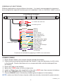
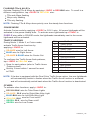
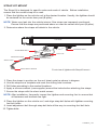
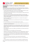
TM
User Manual
Pre-Installation
Wiring & Functions
Vehicle Roof Installation
Adjustable Feet
■ Permanent Mount
■ Strap Kit Mount
Flat Surf Installation
tion
Narrow Surface Mount
Wide Surface Mount
ount
PRE-INSTALLATION
To prevent damage to lightbar and vehicle, ensure that all equipment operates properly,
and carefully plan where to mount and wire the lightbar and controlling equipment:
1. Verify that the lightbar and mounting hardware fit the vehicle.
2. Pre-configure desired lightbar functions.
3. Determine:
■ the location to mount the lightbar.
■ the location to route the lightbar’s Power Cable.
■ the location to route the Function Cable, (eg. to siren, switch box, console).
WARNING: Take extreme care when routing wires around airbag areas to not interfere
with it’s proper operation.
4. Separate all electronic equipment wiring from two-way radio equipment wiring.
5. To avoid interference, keep two-way radio antennas a minimum of 50cm away
from warning equipment.
6. After drilling holes, deburr and smooth sharp edges, and insert grommets to protect
the wires from chafing.
7. When frame-ground the equipment, use the manufacturer-supplied ground locations in
the vehicle.
TORRENT_v.A8
-1-
WIRING & FUNCTIONS
Different applications require different functions. It is highly recommended to determine
and configure the required functions prior to Installation; (refer to ‘CONTROL CABLE’ section).
LIGHTBAR WIRING
POWER CABLE
RED
RED
to +12VDC with 40A fuse
BLACK
BLACK
CONTROL CABLE
to chassis ground
BROWN
PINK
RED
GRAY
ORANGE
BLUE
BROWN-BLK
ORANGE-BLK
BLUE-BLK
YELLOW
GREEN
RED-BLK
YELLOW-BLK
GREEN-BLK
PURPLE
WHITE
Mode 1
Mode 2
Mode 3
Cruise Mode
Rear "Left Arrow"
Rear "Right Arrow"
Take Downs
Right-Side Alley Lights
Left-Side Alley Lights
Flash Pattern
Hi/Low Power
Flashing TDs & Alleys
Front cutoff
Rear cutoff
Program Mode
no function
Functions are activated by applying +12VDC to a control wire.
POWER CABLE
1. Route Power Cable to the vehicle firewall towards the battery.
2. Follow factory wiring harness through the firewall. It may be necessary to drill a hole
in the firewall. Ensure that there are no components that could be damaged from
the drilling.
3. Route the cable to the battery.
4. Splice the 2 RED wires to form a single wire.
5. Install a 40Amp fuse (user-supplied) on the end of RED wire, then connect to battery.
6. Splice the 2 BLACK wires to form a single wire.
7. Connect BLACK wire to the factory chassis ground adjacent to the battery.
NOTE: make sure that all wires of power cable are securely connected to power source.
TORRENT_v.A8
-2-
CONTROL CABLE
1. Route Control Cable towards the dash area to a switch panel (user-supplied).
2. Connect the required wires to the switch panel.
MODE 1
In Mode 1, the flash patterns can be selected from a list of harmonized standard
flash patterns. Activate Mode 1 by applying +12VDC to BROWN wire.
To configure its flash pattern, tap +12VDC to YELLOW wire:
Once for next pattern (refer to Mode 1 Flash Patterns chart).
Quickly 3 times for reset to FP#0.
Mode 1 Flash Patterns
FP#
0
Outside-In Single
10
Single-Quad (split)
1
Outside-In Ultra
11
Single H/L (split)
2
Side-by-Side Single
12
Single (all)
3
Side-by-Side Ultra
13
Double (all)
4
Single (split)
14
Quad (all)
5
Double (split)
15
Quint (all)
6
Quad (split)
16
Mega (all)
7
Quint (split)
17
Ultra (all)
8
Mega (split)
18
Single-Quad (all)
9
Ultra (split)
19
Single H/L (all)
NOTE: While in the “split” patterns, applying +12VDC to GRAY wire will activate
cross patterns.
CROSS PATTERNS
In Mode 1, the “split” flash patterns can be changed to “cross” pattern. The cross
pattern allows front left lightheads to synchronize with rear right lightheads; and front
right lightheads to synchronize with rear left lightheads. The 2 groups of synchronized
lightheads will alternate in a cross like pattern. To activate this function, apply +12VDC
to GRAY wire.
TORRENT_v.A8
-3-
MODE 2
In Mode 2, the flash patterns can be configured in pairs, providing very intense warning
effect. Activate Mode 2 by applying +12VDC to PINK wire. It has, has priority over
Mode 1 if both modes are activated.
To configure its flash pattern:
1. Activate Mode 2 and enter PROGRAM
mode by quickly tapping +12VDC to
PURPLE wire 3 times within 1 second.
FP#
0
Lighthead Patterns
Steady
1
Single Slow (split)
2. Once in PROGRAM mode, all lightheads
will faintly blink every second. The inner
forward-facing pair of lightheads will be
activated.
2
Single Mid (split)
NOTE: If the inner foward-facing heads are
Take Downs, then tap +12VDC to
PURPLE wire once to scroll to the
next pair of lightheads.
11
Off
3
Single Fast (split)
4
Double 1 (split)
5
Double 2 (split)
6
Quint (split)
7
Ultra (split)
8
Single-Quad (split)
9
Single H/L (split)
3. Tap +12VDC to YELLOW wire:
Once for next pattern (refer to
Lighthead Patterns).
Quickly 3 times within 1 second for
reset to FP#0.
10
Random
4. Scroll to the next pair of lightheads by
tapping +12VDC to PURPLE wire.
16
Double 2 (all)
5. Repeat steps 2 and 3 until all lightheads
are properly configured.
17
Quint (all)
18
Ultra (all)
6. Exit PROGRAM mode by quickly tapping
+12VDC to PURPLE wire 3 times within 1
second.
19
Single-Quad (all)
20
Single H/L (all)
12
Single Slow (all)
13
Single Mid (all)
14
Single Fast (all)
15
Double 1 (all)
TORRENT_v.A8
-4-
MODE 3
In Mode 3, the flash patterns can be configured in pairs similar to Mode 1. In Mode 3,
the flashing TD & Alleys function will be automatically activated. Activate Mode 3 by
applying +12VDC to RED wire. It has priority over Mode 1 and Mode 2 if all modes
are activated.
To configure its flash pattern:
1. Activate Mode 3 and enter PROGRAM
mode by quickly tapping +12VDC to
PURPLE wire 3 times within 1 second.
FP#
Lighthead Patterns
0
Steady
1
Single Slow (split)
2. Once in PROGRAM mode, all lightheads
will faintly blink once every second. The
inner forward-facing pair of lightheads
will be activated.
2
Single Mid (split)
3
Single Fast (split)
4
Double 1 (split)
5
Double 2 (split)
NOTE: If the inner foward-facing heads are
Take Downs, then tap +12VDC to
PURPLE wire once to scroll to the
next pair of lightheads.
6
Quint (split)
7
Ultra (split)
3. Tap +12VDC to YELLOW wire:
Once for next pattern (refer to
Lighthead Patterns).
Quickly 3 times within 1 second for
reset to FP#0.
4. Scroll to the next pair of lightheads by
tapping +12VDC to PURPLE wire.
5. Repeat steps 2 and 3 until all lightheads
are properly configured.
6. Exit PROGRAM mode by quickly tapping
+12VDC to PULE wire 3 times within 1
second.
8
Single-Quad (split)
9
Single H/L (split)
10
Random
11
Off
12
Single Slow (all)
13
Single Mid (all)
14
Single Fast (all)
15
Double 1 (all)
16
Double 2 (all)
17
Quint (all)
18
Ultra (all)
19
Single-Quad (all)
20
Single H/L (all)
NOTE: Traffic Arrow functions cannot be activated while in MODE 3.
TORRENT_v.A8
-5-
FLASHING TDs & ALLEYs
Activate Flashing TDs & Alleys by applying +12VDC to RED-BLK wire. To scroll to a
different configuration, tap +12VDC to YELLOW wire:
TDs and Alleys flashing
Alleys only flashing
TDs only flashing
NOTE: Flashing TDs & Alleys have priority over the steady burn functions.
CRUISE MODE
Activate Cruise mode by applying +12VDC to GRAY wire. All corner lightheads will be
activated in low power steady burn. To activate more lightheads tap +12VDC to
PURPLE wire while in CRUISE mode; the lightheads immediately next to the corner
lightheads will be activated.
TRAFFIC ARROWS
During Mode 1, Mode 2, or Cruise mode,
activate Traffic Arrow functions by
applying +12VDC to:
ORANGE wire for Left Arrow.
BLUE wire for Right Arrow.
ORANGE & BLUE wires for Center Out.
To configure the Traffic Arrow flash patterns,
tap +12VDC to YELLOW wire:
Once for next pattern (refer to Traffic Arrow
Patterns chart).
Quickly 3 times within 1 second for reset
to FP#0.
FP#
0
Traffic Arrow Patterns
Sweep Single
1
Sweep Double
2
Sweep Triple
3
Sweep Single End-Double
4
Solid
5
Solid End-Double
6
Solid Chaser
7
Solid Fade
8
Blink Double
9
Blink Triple
10
Blink Solid
NOTE: If the bar is equipped with the Dual Color Traffic Arrow option, the rear lightheads
will automatically switch to Amber when the Traffic Arrow function is activated;
and will automatically switch back when the Traffic Arrow function is deactivated.
OTHERS
To activate other functions, apply +12VDC to:
BROWN-BLK wire for Take Down Lights
ORANGE- BLK wire for Right-Side Alley Light
BLUE-BLK wire for Left-Side Alley Light
YELLOW- BLK wire for Front cutoff
GREEN- BLK wire for Rear cutoff
GREEN wire for Low Power
TORRENT_v.A8
-6-
VEHICLE ROOF INSTALLATION
ADJUSTABLE FEET
Install Mounting Feet on the Lightbar
1. Turn the lightbar upside down.
2. Place mounting feet over the carriage bolts.
3. Attach a lockwasher and a nut on each of the carriage bolts, but do not completely
tighten the bolts. Leave them loose enough to reposition the mounting foot.
FOOT PAD
STOP NUT
SPLIT LOCKWASHER
MOUNTING FOOT
CARRIAGE BOLT
Upside down view of lightbar with mounting foot
TORRENT_v.A8
-7-
PERMANENT MOUNT
Installation includes centering the lightbar on the vehicle’s roof, leveling the lightbar,
and scribing and drilling holes for mounting the lightbar permanently to the roof.
1. Place lightbar on the vehicle roof at the desired location. The lightbar is usually
centered on the door center post (B-pillar).
2. Adjust both mounting feet in or out as necessary until the foot pads rest near the
edge of the roof or gutter where the roof is the most rigid. Make sure the lightbar
and the mounting feet are centered left to right on the vehicle.
3. Level the lightbar by shifting the lightbar slightly forward or back.
4. Using the mounting feet as a template, mark two drilling holes on each end of the
vehicle roof.
5. Carefully remove the lightbar and turn it upside down, and ensure that the mounting
feet do not shift place.
6. Tighten the nuts that secure the mounting feet to the lightbar.
7. Drill four holes at the previously marked drilling positions.
WARNING: DO NOT DRILL THROUGH the roof support structure that spans the
distance between the driver’s and passenger’s side. Drilling through
this will weaken the roof of the vehicle.
NOTE: Before drilling holes, ensure that the holes will go through sheet metal
and not the upholstery. And ensure that no damages are caused to the
vehicle components.
8. Place lightbar on the vehicle roof and align the mounting holes with the mounting feet.
Secure mounting feet to vehicle roof with carriage bolts.
LIGHTBAR
MOUNTING FOOT
FOOT PAD
MOUNTING BOLT
VEHICLE ROOF
Front view of lightbar with Permanent mount
NOTE: After installation, frequently inspect the lightbar and mounting feet to ensure that
all fasteners and brackets are tight.
TORRENT_v.A8
-8-
STRAP KIT MOUNT
The Strap Kit is designed for specific make and mode of vehicle. Before installation,
ensure that the correct strap kit is used.
1. Place the lightbar on the vehicle roof at the desired location. Usually, the lightbar should
be centered on the center door post (B-pillar).
NOTE: Water may leak into the vehicle interior if the straps are improperly positioned.
Ensure that the straps are positioned above or near the center door post (B-pillar).
2. Determine where the straps will attach to the vehicle.
LIGHTBAR
MOUNTING FOOT
ADJUSTMENT BOLT
FOOT PAD
MOUNTING STRAP
VEHICLE ROOF
STRAP FOAM
STRAP MOUNT SCREW
Front view of lightbar with Strap Kit mount
3. Place the straps in position on the roof sheet metal as shown in diagram.
4. Use the straps as a template and mark the drilling hole locations.
5. Drill holes according to the marked locations.
6. Apply a silicone sealant (user-supplier) around the holes before attaching the straps.
7. Secure the straps with the sheet metal screws.
NOTE: After installation, frequently inspect the lightbar and mounting feet to ensure that
all fasteners and brackets are tight.
8. Place the lightbar on the vehicle roof, and align strap bolt holes with lightbar mounting
.
feet bolt holes.
9. Insert adjustment bolt through strap bolt hole all the way to mounting feet bolt hole.
10. Tighten bolts.
TORRENT_v.A8
-9-
FLAT SURFACE INSTALLATION
NARROW SURFACE MOUNT
1. Turn the lightbar upside down.
2. Place mounting feet over the carriage bolts.
3. Attach a lockwasher and a nut on each of the carriage bolts, but do not completely
tighten the bolts. Leave them loose enough to reposition the mounting foot.
MOUNTING BOLT
MOUNTING BOLT
MOUNTING BRACKET
SPLIT
LOCKWASHER
Hardware for Narrow Surface Mount
STOP NUT
4. Place lightbar on the mounting surface at the desired location.
5. Adjust both mounting foot assemblies in or out as necessary. If possible, try to keep
mounting feet near the ends of the lightbar.
6. Using the mounting feet as a template, mark two drilling holes on each end of the
mounting surface.
7. Carefully remove the lightbar and turn it upside down, and ensure that the mounting
feet do not shift place.
8. Tighten the nuts that secure the mounting feet to the lightbar.
NOTE: Before drilling holes in ANY part of the vehicle, be sure that both sides of the
mounting surface are clear of parts that could be damaged, such as brake lines,
fuel lines, electrical wiring, or other vital parts.
9. Drill four holes at the previously marked drilling positions.
10. Place lightbar on the mounting surface and align mounting holes with
the mounting feet.
11. Secure mounting feet to mounting surface with carriage bolts.
MOUNTING
BRACKET
FLAT MOUNTING SURFACE
FLATWASHER
SPLIT LOCKWASHER
MOUNTING BOLT
STOP NUT
Lightbar mounted on flat narrow surface
TORRENT_v.A8
- 10 -
WIDE SURFACE MOUNT
1. Turn the lightbar upside down.
2. Place mounting feet over the carriage bolts.
3. Attach a lockwasher and a nut on each of the carriage bolts, but do not completely
tighten the bolts. Leave them loose enough to reposition the mounting foot.
LOCK NUT
SPLIT LOCKWASHER
FOOT PAD
MOUNTING BRACKET
CARRIAGE BOLTS
Upside down view of lightbar with mounting foot
4. Place lightbar on the mounting surface at the desired location.
5. Adjust both mounting foot assemblies in or out as necessary. If possible, try to keep
mounting feet near the ends of the lightbar.
6. Using the mounting feet as a template, mark two drilling holes on each end of the
mounting surface.
7. Carefully remove the lightbar and turn it upside down, and ensure that the mounting
feet do not shift place.
8. Tighten the nuts that secure the mounting feet to the lightbar.
NOTE: Before drilling holes in ANY part of the vehicle, be sure that both sides of the
mounting surface are clear of parts that could be damaged, such as brake lines,
fuel lines, electrical wiring, or other vital parts.
9. Drill four holes at the previously marked drilling positions.
10. Place lightbar on the mounting surface and align the mounting holes with the
mounting feet.
11. Secure mounting feet to mounting surface with carriage bolts.
MOUNTING BRACKET
FLAT MOUNTING SURFACE
Side view of lightbar on mounting surface
- 11 -
FLATWASHER
SPLIT LOCKWASHER
LOCK NUT
TORRENT_v.A8