1
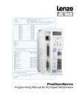
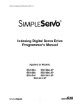
MotionView
Configuration and Programming
Software
USER’S MANUAL
IM94MV01C
Table of Contents
1 MotionView Software Overview . . . . . . . . . . . . . . . . . . . . . . . . . . . . . . . . . . . . . . . . . . 3
1.1
Installation and Package Revision . . . . . . . . . . . . . . . . . . . . . . . . . . . . . . . . . . . . . . . . . . . . . . . . . 3
1.2
Main Screen . . . . . . . . . . . . . . . . . . . . . . . . . . . . . . . . . . . . . . . . . . . . . . . . . . . . . . . . . . . . . . . . . . 4
1.2.1 Node Tree............................................................................................................................4
1.2.2 List View..............................................................................................................................4
1.2.3 Message Window................................................................................................................4
1.2.4 How to Change Parameters................................................................................................5
1.2.5 Main Menu and Toolbar.......................................................................................................6
1.3 Managing Projects . . . . . . . . . . . . . . . . . . . . . . . . . . . . . . . . . . . . . . . . . . . . . . . . . . . . . . . . . . . . . 7
1.4
Connecting to the Drive . . . . . . . . . . . . . . . . . . . . . . . . . . . . . . . . . . . . . . . . . . . . . . . . . . . . . . . . . . 7
1.4.1 Connection using PPP over RS-232/RS485.......................................................................8
1.4.2 Connection using 10/100 Ethernet......................................................................................8
1.4.3 Disconnect or Remove a Drive..........................................................................................11
1.5 Build RS-485 Connection List . . . . . . . . . . . . . . . . . . . . . . . . . . . . . . . . . . . . . . . . . . . . . . . . . . . . 12
1.6
Build Ethernet Connection List . . . . . . . . . . . . . . . . . . . . . . . . . . . . . . . . . . . . . . . . . . . . . . . . . . . 12
1.7
File Operations . . . . . . . . . . . . . . . . . . . . . . . . . . . . . . . . . . . . . . . . . . . . . . . . . . . . . . . . . . . . . . . 13
1.7.1
1.7.2
Opening and Closing Parameter Files...............................................................................13
Load Parameters from File to Drive...................................................................................13
2Node Tree Folders . . . . . . . . . . . . . . . . . . . . . . . . . . . . . . . . . . . . . . . . . . . . . . . . . . . . . . 13
2.1
Drive . . . . . . . . . . . . . . . . . . . . . . . . . . . . . . . . . . . . . . . . . . . . . . . . . . . . . . . . . . . . . . . . . . . . . . . 13
2.2
Motor . . . . . . . . . . . . . . . . . . . . . . . . . . . . . . . . . . . . . . . . . . . . . . . . . . . . . . . . . . . . . . . . . . . . . . . 14
2.3
Parameters . . . . . . . . . . . . . . . . . . . . . . . . . . . . . . . . . . . . . . . . . . . . . . . . . . . . . . . . . . . . . . . . . . 14
2.4
Communication . . . . . . . . . . . . . . . . . . . . . . . . . . . . . . . . . . . . . . . . . . . . . . . . . . . . . . . . . . . . . . . 15
2.4.1 Ethernet.............................................................................................................................15
2.4.2 RS485 and Modbus...........................................................................................................16
2.4.3 CAN...................................................................................................................................16
2.5 I/O . . . . . . . . . . . . . . . . . . . . . . . . . . . . . . . . . . . . . . . . . . . . . . . . . . . . . . . . . . . . . . . . . . . . . . . . . 16
2.5.1 Digital I/O...........................................................................................................................16
2.5.2 Analog I/O..........................................................................................................................17
2.6 Limits . . . . . . . . . . . . . . . . . . . . . . . . . . . . . . . . . . . . . . . . . . . . . . . . . . . . . . . . . . . . . . . . . . . . . . . 17
2.6.1 Velocity Limits....................................................................................................................17
2.6.2 Position Limits...................................................................................................................17
2.7 Compensation . . . . . . . . . . . . . . . . . . . . . . . . . . . . . . . . . . . . . . . . . . . . . . . . . . . . . . . . . . . . . . . . 17
2.8
Indexer Program . . . . . . . . . . . . . . . . . . . . . . . . . . . . . . . . . . . . . . . . . . . . . . . . . . . . . . . . . . . . . . 18
2.9
Tools . . . . . . . . . . . . . . . . . . . . . . . . . . . . . . . . . . . . . . . . . . . . . . . . . . . . . . . . . . . . . . . . . . . . . . . 18
2.9.1 Oscilloscope......................................................................................................................18
2.9.2 Run Panels........................................................................................................................20
2.9.3 Diagnostic..........................................................................................................................20
2.10 Faults . . . . . . . . . . . . . . . . . . . . . . . . . . . . . . . . . . . . . . . . . . . . . . . . . . . . . . . . . . . . . . . . . . . . . . 20
2.11 Documents . . . . . . . . . . . . . . . . . . . . . . . . . . . . . . . . . . . . . . . . . . . . . . . . . . . . . . . . . . . . . . . . . . 20
IM94MV01C Safety Warnings
WARNING!
• Hazard of unexpected motor starting! When using MotionView software, or otherwise operating the
PositionServo drive over RS-232/485, CANopen or Ethernet, the motor may start unexpectedly, which may
result in damage to equipment and/or injury to personnel. Make sure the equipment is free to operate in this
manner, and that all guards and covers are in place to protect personnel.
DANGER!
• Hazard of electrical shock! Circuit potentials are at 115 VAC, 230 VAC or 480 VAC above earth ground.
Avoid direct contact with the printed circuit board or with circuit elements to prevent the risk of serious
injury or fatality. Disconnect incoming power and wait 60 seconds before servicing drive. Capacitors retain
charge after power is removed.
NOTE
• The symbol shown at left indicates additional information, shortcuts, or tips that do not affect the safe
operation of the drive.
IM94MV01C
1
MotionView Software Overview
MotionView is the setup and management tool for SimpleServo and PositionServo Drives. The user interface is intuitive in the
way information is arranged and is logically divided into groups for viewing and editing. This manual covers the concept and
basic operations of the MotionView program, please refer to the corresponding product’s User and Programmer Manuals for
further details on MotionView features and capabilities.
1.1
Installation and Package Revision
MotionView software can be installed on Windows, Windows XP system. To locate the package revision check the MotionView
CD label or open the [Help] folder then the [About MotionView] folder. Each time a file is revised on the MotionView CD, the package revision is increased even though the MotionView revision is not changed. As illustrated in Figure 1, MotionView revision
(6.04), motor database revision (3.01) and package revision (MV94CD14) can be found by clicking [About MotionView].
Figure 1: About MotionView
To obtain the latest revision of the MotionView software, visit the Technical Library at http://www.actech.com.
IM94MV01C 1.2
Main Screen
The user interface or Motion View main screen consists of 3 main panels: the Node Tree, the List View, and the Message Window
as illustrated in Figure 2.
Node
Tree
List
View
Message
Window
Figure 2: MotionView Screen
1.2.1 Node Tree
Drives and Parameter files appear in the Node Tree on the left hand side of the screen. The Drive and Parameter files contain sub
folders (denoted by a + symbol) with parameter groups and different tools needed to work with the selected Drive (Parameter
file). Drive and Parameter Files appear almost identical in the Node Tree and both operate in the same way. The main difference
is that Drive files can have a connection and parameter files cannot. To expand a folder to view it’s subfolders double-click on
the [+] symbol next to it. To collapse a folder double-click on the [-] symbol next to it.
1.2.2 List View
The right panel of the MotionView main screen is called the List View. When you click on a Node Tree file or sub-folder, the
parameters belonging to this group are displayed in the List View. Every parameter can be viewed in detail; its current value,
units and min and max values. When one navigates through the node tree, information in the list view changes automatically
in sync with the node tree selection.
1.2.3 Message Window
The bottom or footer section of the MotionView main screen is called the Message Window. The Message Window gives information about communication status and supplies various information to make troubleshooting easier. To clear the message in the
Message Window, double-click the message and then right click to reveal the [Clear] button. Click [Clear].
IM94MV01C
1.2.4 How to Change Parameters
To change any parameter, click on the parameter of interest on the list view. The dialog box opens and the user can then change
the value. There are several different types of dialog boxes depending on the parameter being changed:
•
A Numeric value parameter with an Entry Dialog Box.
•
A Numeric value parameter with an Entry Dialog Box containing a Slider.
•
A Selection type parameter with a Predefined Value(s) Dialog Box.
The Entry Dialog Box requires the user to input (type) the value of the parameter. The Entry Dialog Box with Slider permits the
user to increase/decrease the value of the parameter by clicking on the slider. A Predefined Value Dialog Box contains a pulldown menu from which the user can select the appropriate value for his parameter setup.
All dialog boxes contain a set of [Apply] [OK] and [Cancel] buttons. Use the [Apply] button to accept the value changes but leave
the dialog box open. Use the [OK] button to accept the changes and dismiss the dialog box. Use the [Cancel] button to dismiss
the dialog box and make no changes to the parameter setup.
Figure 3: Numeric value parameter with an Entry Dialog Box
Figure 4: Numeric Entry Dialog Box with Pull-Down Predefined Values
Figure 5: Numeric Entry Dialog Box containing a Slider
IM94MV01C Some groups from the Node Tree have Action buttons in the List View. They will perform the action listed against the buttons in
the list view. (Refer to Figure 6). Example: clicking “Load fault history” loads the fault history from the PositionServo drive.
Figure 6: Action Buttons embedded in List View
1.2.5 Main Menu and Toolbar
The functions of MotionView are accessible in two ways: via the Main Menu or the Toolbar as illustrated in Figure 7. If a function in a pull-down menu or an icon is greyed out that denotes the function is unavailable. A function may be unavailable
because a drive is not physically connected to the network or the drive is not configured the same as the communication link
in MotionView.
Figure 7: Main Menu and Toolbar
Table 1: Contents of Main Menu Pull-Down Folders
Main Menu
Node
Project
Tools
View
Help
New configuration file
New project
Browse motor database
Toolbar
MotionView help
Open configuration file
Open project
Clear output window
Status Bar
Product manuals
Save configuration file
Close project
About MotionView
Load configuration file
Save project
Time stamp
Set all parameters to default
Save all configuration files
Connect drive
Options
Disconnect all coneected drives
Connection setup
Remove node from project
Recent file
Table 2: Toolbar Icons
Toolbar Icons
Connect
Connected
Disconnected
Add File
Open File
IM94MV01C
Save
Save As
Remove Node
Print
Help
1.3
Managing Projects
Multiple parameter files and drives can be opened at the same time. Information about which files and drives are open and the
current window layout is defined as a Project. A Project can be saved as a file to the PC’s hard drive. Future sessions will allow
opening a project to automatically load the desired files and drives into the node tree and restore the windows layout. Note that
MotionView will try to connect all drives listed in the project.
To save a project to a file, click [Project] on the main menu then [Save project] from the pull-down menu.
To start a new project and close all opened files and drives, click [Project ] fon the main menu then [New project] from the pulldown menu. When you click [New project] all drive connections and file will be closed. The Node Tree will be emptied.
To create a new project using an existing project as a template, click [Project] on the main menu then [Save project As] from
the pull-down menu.
Note:
A Project file does not save parameter files or drive data. It saves the list of opened devices and window positions on the screen. Use [Project] [Save All configuration files] to save changes in all opened files and drives. Use
[Node] [Save] to save each individual file or drive.
1.4
Connecting to the Drive
To be able to view or change a drive’s parameters a connection must be made between the drive and the computer. When you
make a connection you establish a communication link between the physical drive and the MotionView program. MotionView
software supports RS-232, PPP over RS-485/RS-232 and UDP 10/100 Ethernet.
Note:
If the connection is successful, the drive will appear on the node tree.
If the connection is unsuccessful then the drive will not appear on the node tree. The Message Window will then
explain why the connection failed.
Figure 8: RS-232 Setup
IM94MV01C 1.4.1 Connection using PPP over RS-232/RS485
1.
The first time in a session, click [Project] then [Connection Setup] or click the [
face from the list.
2.
Optionally click on the [Properties] button to change “COM Port” number and/or baud rate if necessary. Note that baud
rate assigned in MotionView must be the same as the baud rate set on the drive.
3.
Select [Node] then [Connect drive] or click the [
4.
Specify the address(es) of the drive(s) you want to connect. Refer to paragraph 1.5 “Build RS-485 Connection List” for
details.
5.
Click the [Connect] button.
6.
Drive(s) with specified address(es) will be connected and appear on the left in the Node Tree.
] icon. The Connection dialog box opens as shown in Figure 8.
Figure 9: RS-485 Build List
1.4.2 Connection using 10/100 Ethernet
1.
Configure IP Address of the PC
Click [Start] (In the bottom left-hand corner of your desktop).
Figure 10a: Start
] icon and select the proper inter-
IM94MV01C
Select [Control Panel] from the Start menu.
Figure 10b: Network Connections
Select [Network Connections] in the Control Panel menu.
Select the [Local Area Connection] with the number next to it.
Figure 10c: Local Area Connection
IM94MV01C Under the General tab, select [Internet Protocol (TCP/IP)].
Figure 10d: Internet Protocol TCP/IP
Click [Properties].
Select [Use the following IP Address]
Type “192.168.124.1” in the IP address window.
Figure 10e: Use the following IP address
The Subnet Mask window will automatically populate with 255.255.255.0. Click [OK].
The IP address of the PC has been configured.
10
IM94MV01C
2.
Configure IP Address of Drive:
3.
The first time in a session, click [Project] then [Connection Setup] or click the [
face from the list.
4.
Select [Node] then [Connect drive] or click the [
5.
Specify the IP address(es) of the drive(s) to connect to. Refer to paragraph 1.6 “Build Ethernet Connection List” for
details.
6.
Click the [Connect] button.
7.
The Drive(s) with the specified address(es) will be connected and shown in the Node Tree.
] icon and select the proper inter-
] icon. The connection dialog opens as illustrated in Figure 10.
Figure 10e: Composite Screenshot - Connection using 10/100 Ethernet
1.4.3 Disconnect or Remove a Drive
To disconnect a drive: Select the drive by clicking on its icon on the left tree. Click [Node] on the main menu then [Disconnect]
from the pull-down menu or click the [
] icon. MotionView will prompt to [save the current settings to file] before it disconnects the drive. The user can reconnect the drive later by selecting [Node] on the main menu then [Connect drive] from the
pull-down menu.
To remove a drive or file from the Node Tree: Select the drive or file by clicking on its icon on the left tree. Select [Node] from
the main menu then [Remove node from project] from the pull-down menu.
Note:
A connection does not need to be setup every time the user connects. A connection needs to be setup only once
per session or any time the communication settings are changed.
If the work is saved to a project file then the connection does not need to be setup unless different communication settings are used. Re-save the project file if changes are made to it.
IM94MV01C 11
1.5
Build RS-485 Connection List
Figure 11: Build RS 485 Connection List
1.6
Now
This window shows a list of drives currently connected.
To be
This window shows a list of available drives that could be connected
Cancel
Dismiss dialog box without any action.
Help
Access contents of MotionView Help folder
Scan
Find and connect all drives on the network. A search is performed for all drives in address range 0-31.
Add Add address to the connection list.
Remove Removes highlighted address from the connection list.
Connect One
Specifies one drive’s address to be connected
Connect
Puts the drive selected in the “To be” window into the “Now” window.
Build Ethernet Connection List
Figure 12: Build Ethernet Connection List
12
IP address
Specify a single device address in this field and then click [Connect] to this drive with this IP address.
Connected
Shows drives currently connected
To be connected Shows drives MotionView found on the network and available for connection
- -> X
Removes highlighted addresses from the “To Be Connected” list
Discover
Locates every physically connected drive on the network
Connect
Connects every drive with an IP listed in the “To Be Connected” list box.
Cancel
Dismisses dialog box without any action.
IM94MV01C
1.7
File Operations
1.7.1 Opening and Closing Parameter Files.
To open an existing configuration file, click [Node] on the main menu then [Open configuration file] from the pull-down menu.
Select the configuration file with extension “.dcf” in the open window. The File will appear in the Node Tree on the left.
To save the file, click [Node] on the main menu then [Save configuration file] from the pull-down menu.
To remove a file from the Node Tree, click [Node] on the main menu then [Remove node from project] from the pull-down
menu.
1.7.2 Load Parameters from File to Drive.
To load data from a file to a drive, click [Node] on the main menu then [Load configuration file to drive] from the pull-down menu.
The Drive data will be updated with the file data.
Note:
For this operation the drive must be connected and DISABLED.
Parameters will not be loaded when the drive is enabled.
2Node Tree Folders
Note:
Refer to the PositionServo User’s Manual (S94P01) and Programming Manual (PM94P01) for complete descriptions of motor features and instructions for programming each parameter. To access the PositionServo
Programming Manual, click [Help] then click [Product manuals]. The information contained herein is a brief
description of the folders in the Node Tree that populate once a drive file is opened.
2.1
Drive
Click the Drive name in the Node Tree. The drive ID string, device family, firmware revision, vector processor revision, hardware
revision and serial number are displayed as illustrated in Figure 13. The drive indentification parameters are fixed and are
provided for information only.
Figure 13: Drive ID String
IM94MV01C 13
2.2
Motor
After configuring the interface of the PositionServo drive, the motor needs to be setup if one is attached. To select a motor, click
on the [Motor] folder. Click on the action button [Click here to change the motor] to bring up the motor parameters screen. Set
the motor vendor and motor model number. If the motor is not in the list, click [Create File] to define a new motor setup.
Figure 14: Motor Parameters
2.3
Parameters
To setup the drive’s parameters click on the [Parameters] folder. To set any one of the parameters in the List View on the right,
double-click the parameter name. A dialog box will open for changes to that specific parameter. The parameters that populate
the List View are applicable to the Drive file at the top of the Node Tree. Table 1 lists the parameter name, value, units and
min/max values for the selected E94P090T4N Drive which is a 3-phase, 480V/9A, non-filtered PositionServo 940 encoder-based
drive.
Figure 15: Parameters (Drive)
14
IM94MV01C
Table 3: E94P09T4N Drive Parameters
Parameter Name
Value
Units
Min
Max
Drive name
Drive mode
Torque
Drive PWM frequency
16kHz
Current limit
2.8
A
0.0000
9.0000
8kHz peak current limit
7.2000
A
0.0000
27.0000
16kHz peak current limit
7.2000
A
0.0000
22.500
Analog input (current scale)
0.9000
A/volt
-1.8000
1.8000
Analog input (velocity scale)
100.0000
RPM/volt
-2000.0000
2000.0000
Enable Accel/Decel limits
Disable
Accel limit
1000.0000
RPM/sec
0.1000
5000000.0000
Decel limit
1000.0000
RPM/sec
0.1000
5000000.0000
Reference
External
Step input type
Master encoder
Fault reset
on disable
Motor temperature sensor
Disable
Motor ptc cut-off resistance
2500
Ohm
2000
3000
Second encoder
Disable
Regen duty cycle
10
%
1
100
Encoder repeat source
Drive feedback input
System to master ratio
1:1
-32767:1
32767:32767
Second to prime encoder ratio
1:1
-32767:1
32767:32767
Autoboot
Enabled
Group ID
0
0
32767
Enable switch function
Run
User units
1.0000
0.0000
1000000.0000
Resolver track
0
0
15
Current Limit Max Overwrite
Disable
Revolutions/unit
The “Resolver track” parameter is only applicable to the PositionServo 941 Resolver-based drive. The Resolver track function sets the pulse per revolution (PPR) resolution of the buffered encoder outputs when a resolver motor is used. Refer to the
PositionServo User’s Manual for more details. The Resolver track and Current Limit Max Overwrite functions are available with
PositionServo drive firmware revision 3.06 or higher.
2.4
Communication
There are 3 sub-folders under the [Communications] folder in the MotionView Node Tree. The Ethernet folder contains an action
button [IP setup] that permits the user to configure the Ethernet interface. The [RS485 and Modbus] folder contains the configuration data of the Modbus interface. The [CAN] folder contains the configuration data for the CAN interface.
2.4.1 Ethernet
The Ethernet folder contains an action button [IP setup] that permits the user to configure the Ethernet interface. Click on the
[IP setup] button to view/change the Ethernet interface setup (The Ethernet interface may have been previously configured with
[Project] [Configuration setup], paragraph 1.3.2). In [IP setup], the user can specify the IP address.
IM94MV01C 15
2.4.2 RS485 and Modbus
The [RS485 and Modbus] folder contains the configuration parameters of the Modbus interface. Click on any Modbus parameter
to change it. Table 4 lists the range and default value of each RS485 Modbus parameter.
Table 4: RS 485 Modbus Parameters
Parameter
Range
Default Value
RS 485 Configuration
Normal, Modbus slave
Normal
Modbus baud rate
2400, 4800, 9600, 19200, 38400, 57600, 115200
19200
Modbus reply delay
0 - 1000ms
0
Modbus parity
No Parity, Odd, Even
No Parity
Modbus stop bits
1.0, 1.5, 2.0
1.0
2.4.3 CAN
The [CAN] folder contains the configuration parameters for the CAN interface. Click on Parameter name to change the setting
of that parameter. Table 5 lists the range and default value for each CAN parameter.
Table 5: CAN Parameters
2.5
Parameter
Range
Default Value
CAN Control
Disabled, CANOpen Simple, CANOpen 402
Disabled
CAN baud rate
10k, 25k, 50k, 125k, 250k, 500k, 800k, 1000k
500k
CAN Address
1 - 127
1
CAN Bootup Mode
Pre-operational, Operational, Pseudo master mode
Pre-operational
CAN Bootup Delay
0-5 sec
5 sec
I/O
There are 2 sub-folders under the [I/O] folder in the MotionView Node Tree. The [Digital I/O] folder contains the values of the 4
outputs and debounce times for the 12 inputs. The [Analog I/O] folder contains the values of the one output and one input plus
an action button [Adjust analog input zero offset] that permits the user to change the analog zero offset.
2.5.1 Digital I/O
The [Digital I/O] folder contains the values of the 4 outputs and debounce times for the 12 inputs (A1-A4, B1-B4, C1-C4).
Table 6: Digital Input/Output Parameters
16
Parameter
Range
Default Value
Output 1 function
Not assigned, Zero Speed, In speed window, Current
limit, Run time fault, Ready, Brake, In position
Not assigned
Output 2 function
Not assigned, Zero Speed, In speed window, Current
limit, Run time fault, Ready, Brake, In position
Not assigned
Output 3 function
Not assigned, Zero Speed, In speed window, Current
limit, Run time fault, Ready, Brake, In position
Not assigned
Output 4 function
Not assigned, Zero Speed, In speed window, Current
limit, Run time fault, Ready, Brake, In position
Not assigned
Input A1 debounce time
0-1000 ms
0
Input A2 debounce time
0-1000 ms
0
Input A3 debounce time
0-1000 ms
0
Input A4 debounce time
0-1000 ms
0
Input B1 debounce time
0-1000 ms
0
Input B2 debounce time
0-1000 ms
0
Input B3 debounce time
0-1000 ms
0
Input B4 debounce time
0-1000 ms
0
Input C1 debounce time
0-1000 ms
0
Input C2 debounce time
0-1000 ms
0
Input C3 debounce time
0-1000 ms
0
Input C4 debounce time
0-1000 ms
0
Hard limit switches action
Not assigned, Fault, Stop and fault
Not assigned
IM94MV01C
2.5.2 Analog I/O
The [Analog I/O] folder contains the parameters of one output and one input plus an action button [Adjust analog input zero
offset] that permits the user to change the analog zero offset.
Table 7: Analog Input/Output Parameters
Parameter
Range
Default Value
Analog output
Not assigned, Phase current RMS, Phase current Peak,
Motor velocity, Phase R current, Phase S current, Phase
T current, Iq current, Id current
Not assigned
Analog output current scale
0.1000 - 10.000 Volt/Amp
1.0000
Analog output velocity scale
0.1000 - 5.0000 mV/RPM
1.0000
Analog input dead band
0 - 50 mV
10
Analog input offset
-1000 - 1000 mV
0
Note: Phases R, S and T are equivalent to phases U, V and W respectively.
2.6
Limits
There are 2 sub-folders under the [Limits] folder in the MotionView Node Tree for setting the velocity and position limits.
2.6.1 Velocity Limits
To set the velocity limits of the PositionServo drive in MotionView, double click on the [Limits] folder to expand it then click on the
[Velocity limits] folder to open this function. Table 8 lists the range and default value of each of the Velocity limits parameters.
Table 8 Velocity Limits Parameters
Parameter
Range
Default Value
Zero speed
0 - 100 RPM
10
Speed window
10 - 10000 RPM
100
At speed
-10000 - 10000 RPM
10000
2.6.2 Position Limits
To set the position limits of the PositionServo drive in MotionView, double click on the [Limits] folder to expand it then click on the
[Position limits] folder to open this function. Table 9 lists the range and default value of each of the Position limits parameters.
Table 9: Position Limits Parameters
2.7
Parameter
Range
Default Value
Position error
1 - 32767 counts
500
Max Error Time
0.2500 - 8000.0000 ms
500.0000
Second encoder Position error
1 - 32767 counts
500
Second encoder Max Error Time
0.2500 - 8000.0000 ms
500.0000
Compensation
To set the Compensation parameters, click the [Compensation] folder to open its contents in the List View window. To change
a compensation parameter, click the Parameter name. Table 10 lists the range and default value of each compensation parameter.
Table 10: Compensation Parameters
Parameter
Range
Default Value
Velocity P-gain
0.0000 - 32767.0000
600.0000
Velocity I-gain
0.0000 - 16383.0000
0.0000
Position P-gain
0.0000 - 32767.0000
600.0000
Position I-gain
0.0000 - 16383.0000
0.0000
Position D-gain
0.0000 - 32767.0000
0.0000
Position I-limit
0.0000 - 20000.0000 RPM
200.0000
Gain scaling
-16 - 4
-4
IM94MV01C 17
2.8
Indexer Program
Click on the [Indexer program] folder to open the MotionView Studio (the List View window is gray when MotionView Studio is
selected). The user can type program code in the MotionView Studio or import it from a file, compile the program, step in/over
it, run it , then compile with the option of sending the compiled program directly to the drive.
The PositionServo Programming Manual contains full details on the MotionView Studio and the Indexer Program. To access the
PositionServo Programming Manual, click [Help] then click [Product manuals].
2.9
Tools
There are 3 sub-folders under the [Tools] folder in the MotionView Node Tree. The Oscilliscope tool provides a real-time display
of the PositonServo drive’s behavior. The [Run panels] folder contains an action button [Check phasing] that permits the user
to check the phase of the motor. The [Diagnostic] folder contains an action button [Show variables] that permits the user to
access the list of variables.
2.9.1 Oscilloscope
The Oscilloscope tool provides a real-time display of the different electrical signals inside the PositionServo drive. Like a “real”
oscilloscope, the Scope tool displays two channels simultaneously. The signals in Table 11 can be observed using the Oscilloscope tool. Click on the [Oscilloscope] folder to open the Oscilloscope in a separate window. Click on the [RUN]/[STOP] button
to start or stop the scope display. Click on the [Close] button to close the Oscilloscope display.
Table 11: Oscilloscope Parameters
Parameter
Description
Phase Current (RMS)
Motor phase (RMS) current
Phase Current (Peak)
Motor phase peak current
Iq Current
Motor Iq (torque producing) current
Motor Velocity
Actual motor speed in RPM
Commanded Velocity
Desired motor speed in RPM (velocity mode only)
Velocity Error
Difference in RPM between actual and commanded motor speed
Position Error
Difference between actual and commanded position (Step and Direction mode only)
Bus voltage
DC bus voltage
Analog input
Voltage at the drive’s analog input
Target position
Requested position
Absolute position
Absolute position (actual position)
Target position pulses
Absolute position pulses
Secondary absolute position
Position increment
Secondary position error
18
IM94MV01C
Figure 16: Oscilloscope Display
Signal Name
You can customize the information presented by the Scope tool by choosing the drop-down box in each channel. The set of
available signal depends on the drive model. Refer to the User’s Manual appropriate for your drive model to see the list of the
signals.
Scale
Scale sets the sensitivity of the display. Each division is considered one unit of the selected scale. A scale of 100 RPM/div, for
example, means that the signal will rise (or descend) by one division for every change of 100 RPM in the signal level. Thus, a
500-RPM signal would deflect the signal by five divisions from the central reference line.
Offset
Offset sets the vertical distance from the central base line to the signal trace. This is useful if you want to compare two signals.
For example, if you wish to compare the actual vs. commanded motor velocity, you would enter an offset that would move the
two signals to the same side of the central reference line.
Time Base
Time base sets the number of cycles displayed per division. Higher frequencies have a shorter time base than lower frequencies. If you wanted to display one cycle of a particular signal, your time base setting would therefore be lower for high-frequency
signals than for low-frequency signals.
Trigger/Trigger Level
Trigger level specifies the signal level after which the scope starts acquiring data. You can also specify which channel will be a
source for the trigger. The oscilloscope display will continue to run while the signal level crosses the specified level (above if the
trigger is set for rising or leading edge, or below if the trigger is set for trailing or falling edge).
Single
Also called one-shot trigger. If Single Sweep is selected, data acquisition will be stopped after the scope buffer is filled and data
displayed on the screen (frozen data). To repeat data acquisition, you will need to click the Single again.
IM94MV01C 19
Always on top
Select this button to display the oscilloscope window on top all other windows.
Options
Select this button to change the channel mode, display mode and channel width settings. The default settings are: channel
mode: normal, display mode: connected lines and channel width: average maximum.
2.9.2 Run Panels
The [Run panels] folder permits the user to check the phasing of the motor. Click on the [Run panels] folder then click the action
button [Check phasing] to check the phasing of the motor. The motor data is not modified when checking the phase.
2.9.3 Diagnostic
The [Diagnostic] folder permits the user to check the drive’s variables. Click on the [Diagnostic] folder then click the action button [Show variables] to open the list of the drive’s variables.
2.10 Faults
The [Faults] folder contains two action buttons. The [Load fault history] permits the user to load the fault history of the drive onto
the computer. The sixteen most recent faults are displayed with the newer faults replacing the older faults in a first-in first-out
manner. In all cases, fault #0 is the most recent fault. The [Reset fault history] permits the user to clear the fault history of the
drive from within the MotionView program.
2.11 Documents
The [Documents] folder contains the Release notes for the installed version of MotionView software. Click on the document title
to open a hypertext link to the AC Technology’s Technical Library.
Note:
Refer to the PositionServo User’s Manual (S94P01) and Programming Manual (PM94P01) for complete descriptions of motor features and instructions for programming each parameter. To access the PositionServo
Programming Manual, click [Help] then click [Product manuals]. The information contained herein is a brief
description of the folders in the Node Tree that populate once a drive file is opened.
20
IM94MV01C
AC Technology Corporation • 630 Douglas Street • Uxbridge, MA 01569 • USA
+1 (508) 278-9100
IM94MV01C 21