1
no responsibility for your actions with this board. I will offer no further advice than what you
see here in italics:
Transformer rating: Secondaries: 18-0-18 @ 250mA or 18-0, 18-0 @ approx 15VA total
Connect common, or centre tap, to AC1 and/or AC0. Others to AC2 and AC3.
Line fuse: T250mA
All mains carrying conductors must be suitably insulated and mounted away from the low
voltage parts of the unit.
All parts of the metal case MUST be connected to mains safety earth. A suitable and secure
bonding point must be made to the case. Note that any case paint or other coating should be
removed from around the bonding point to ensure that the metalwork is making a good
contact to the bonding point hardware. The bonding point should then be connected via a
suitably thick piece of wire back to the earth terminal of the IEC socket or earth inlet
connection.
If you have used a laminated EI transformer, ie. not a toroid, then you should earth the
exposed metal frame of the transformer.
0V on the Filtrex-II circuit board should also be tied to earth. This should be done using a
piece of insulated wire connecting the earth bonding point to pin 2 or 3 of the MOTM pad on
the board.
Powering the Filtrex with the MOTM header
The Filtrex may also be powered from the MOTM or Oakley power busses. The power socket
is 0.156” Molex/MTA 4-way header is marked as MOTM on the PCB. Friction lock types are
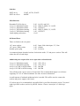
recommended. The pin out is as follows:
Power
Pin number
+15V
Module GND
Module GND
15V
1
2
3
4
Pin one is depicted by the diagonal on the legending. If you are using the MOTM system to
power your Filtrex, be sure not to fit the following components which make up the Filtrex's
own +/-15V regulated supply:
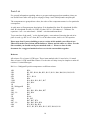
U15, U11, D13, D14, D18, D19, D9, D24, C40, C47, C38, C50
You can also use the Filtrex to power other MOTM/Oakley modules using the MOTM
header. However, be sure not to exceed the power rating of the wallwart, transformer,
heatsinks and smoothing capacitors.
16