1
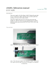
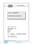
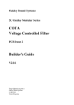
Oakley Sound Systems
TM3030
PCB Issue 1
User manual & Builder's Guide
V1.1.2
Tony Allgood B.Eng PGCE
Oakley Sound Systems
CARLISLE
United Kingdom
Introduction
The Oakley TM3030, pronounced as 'tee-emm-thirty-thirty', is a revised and cut down edition
of the hugely popular TB3030 project. It is designed to be built into half of a 1U 19" rack or
other half rack case of your choice. All the seven knobs, the one switch and the four LEDs are
designed to be mounted directly onto the printed circuit board. This simplifies building and
reduces the possibilities of any mistakes in construction.
However, unlike the Oakley TB3030 and TB3031, this project has its own midi interface on
board. This interface has been especially designed for us by Sequentix, the creators of the P3
Sequencer and midibass TB303 midi interface. By careful analysis of the original unit,
Sequentix have created a midi interface that allows the TM3030 to behave as the original unit
would if you could feed it midi messages. Slides and accents are faithfully reproduced.
This unit contains no internal sequencer. Now I know part of the sound of those famous acid
riffs come from the behaviour sequencer, but with careful programming on your favourite
computer or hardware sequencer, it is still possible to create those wonderful fluid lines that
are so recognisable.
The PCB contains, in several key areas, places where the builder can chose to use modern or
original Japanese parts. We believe that the modern parts sound as good as the originals, but
the option is there if you have the parts and want authenticity.
For general information regarding where to get parts and suggested part numbers please see
our useful Parts Guide at the project webpage or http://www.oakleysound.com/parts.pdf.
For general information on how to build our modules, including circuit board population,
mounting front panel components and making up board interconnects please see our
Construction Guide at the project webpage or http://www.oakleysound.com/construct.pdf.
Power Supply
The power requirements are 15V AC, or 18V to 24V DC. Current consumption is no more
than 80mA. We assume the builder will be using a mains adapter to power the TM3030.
Mains adapters are also called 'power packs', 'battery eliminators' and 'wallwarts'. They are
available in linear regulated, linear unregulated or switch mode types. The TM3030 can be
used with either of the linear types. Switch mode wallwarts produce a noisier output signal
and can interfere with other audio equipment. From my experience in buying wallwarts, I
would recommend that you look for either a 15V AC output type, or 24V DC unregulated
type.
If you are using a DC output power pack, the TM3030 will function safely on any polarity
setting. ie. the tip can be either positive or negative.
The choice of connector is yours. However, most wallwarts come with a 2.5mm power plug.
These are not the same as a 2.5mm jack, but are small circular tubes, the inside of which is one
contact and the outer layer the other.
2
Which ever socket you use, and whether you use a DC or AC wallwart, you must ensure that
the supply inlet socket is insulated from the case chassis. This simply means you must use a
plastic cased socket and not one with a metal screw or mounting bush. These should be easily
available from your parts supplier.
I'll deal with the actual connections in a later part of this documentation.
I do not endorse any method that uses the direct powering of any Oakley equipment with the
mains supply. It is up to you to use your PCB wisely and to make sure you make your project
in a safe manner. Furthermore you should ensure that the finished project is safe to any
persons who are using it. Neither I or Paul Darlow can take any responsibility for your actions
with this board.
The following advice is only for those who know how to wire mains rated equipment safely. If
you do not know how to do this then make no attempt to do so. The following information
provided in italics is the only information I am prepared to give regarding direct mains supply
for the TM3030.
Transformer rating: Secondaries: 15-0 or 7.5-0-7.5 @ 3VA minimum
Do not connect common of any dual secondary windings to ground. Winding end wires go to
pin 1 and pin 2 of the connector marked AC power. Neither pin 1 or pin 2 should be
connected to ground.
C16 should be adequately rated for the input voltage you are using. ie. At least equal to
1.4xVac. Where Vac is the maximum output RMS voltage of the transformer.
Line fuse: T250mA
All parts of the metal case MUST be earthed to mains safety earth via a suitably low
resistance bonding strap or wire. 0V on the board should also be tied to earth via a 100R
resistor.
3
Operating Instructions
The following will be a description of the pots and switches in the TM3030.
Reading the front panel of the TM3030 from left to right:
TUNE: This rotary control alters the frequency of the VCO and thus tunes the whole
instrument. Default tuning would normally be expected in the central position.
VCO WAVE: This is a little switch that selects the waveform that is then passed to the filter.
The VCO produces two waveforms, the square wave, a hollow sound; and a sawtooth wave, a
more brassy sound. Neither output is actually a text book representation of these waveforms.
The TM3030 produces a very unusual square wave that is very distinctive in sound.
The actual VCO core actually produces a sawtooth waveform. This is converted into a square
wave by a simple single transistor waveshaper.
FREQUENCY: This alters the voltage controlled filter’s cut-off frequency. The more
clockwise the pot the brighter the sound. The filter inside the TM3030, like the original
device, is a four pole diode ladder. The roll-off in the initial part of the response is
approximately -18dB per octave, which is actually closer to that of an ideal three pole filter.
SLIDE LED: Lights red when a slide is activated. This is done automatically by the midi
interface when it receives two overlapping notes, ie. playing legato. You will see this flicker in
normal operation even if no slides are enabled. This is because the TM3030's midi interface
exactly mimics the actions of the original design which produced spurious control signals to
the glide circuitry.
RESONANCE: This alters the amount of feedback applied to the filter. What this does is to
create a peak in the filter’s response. Thus certain frequencies are heavily emphasised. It also
controls the amount that the accent signal modulates the filter’s cut-off. This last bit is rather
unusual, but it gives the TM3030 its characteristic ‘th-wap’ sound when accents are triggered.
AMOUNT: The filter’s cut-off frequency can be modulated with an envelope generator. Thus
dynamic filtering is possible. By increasing the amount of envelope modulation, the cut-off
point is increasingly moved by the envelope generator. The generator itself is triggered by the
gate signal, and produces a decaying voltage immediately after being triggered. This produces
the characteristic ‘dow’ sound. Oddly, the envelope amount also gets higher for repeated
triggering of the gate.
The TM3030's envelope sweep can actually be turned off by turning the pot completely anti
clockwise. The original device actually can't do this, so if you want to recreate the limitations
of the original unit you should not take this pot down to zero. However, it should be noted
that many original units have been modified to allow for zero modulation.
GATE LED: Lights green when an active gate is present. Not all midi notes are recognised
by the TM3030. The unit has only a six bit digital to analogue convertor (DAC) which is
identical in design to the one in the original device. Therefore, only half of all the 127 midi
4
note numbers are able to trigger the TM3030. The lowest note that is played is C3 (where
middle C is C4), lower notes that this are ignored.
VCF DECAY: Controls the time it takes for the filter envelope to decay down to zero. From
‘dit’ sounds to ‘dowww’ sounds. This pot will have no effect on accented notes when the
decay time is set automatically to its lowest value.
ACCENT LED: Lights yellow when an accent is detected. Accents are triggered
automatically by the midi interface when the incoming midi note has a velocity value over a
certain value. This value can be set up as anything you want by using a suitable system
exclusive message to the midi interface. However, by default it is set at velocity value 100.
ACCENT: When accent is triggered the VCA can become louder and more punchier. This
pot controls how much the accent has an effect. Like the original device, the accent signal
triggers a third envelope generator circuit which controls the filter's cut-off frequency. The
amount that the accent affects the VCF is controlled both by both this pot, and the resonance
pot.
Accent also affects the decay time of the filter envelope generator. When accent is triggered
the decay time is automatically set to its minimum value and the VCF Decay pot has no affect.
POWER LED: Lights red when the device is powered up. Remember though, if you are
powering your TM3030 with an external wallwart, you need to ensure that the wallwart is
switched off or removed from the wall socket when you are not using the unit.
VOLUME: Controls the final output level. The output circuitry is faithfully copied from the
original device and as such behaves in a less than ideal way. You will find that by loading the
output with different impedances you can change the sound. Lower impedances will load the
output producing distortion.
5
Buying Your Electronic Components
Most of the parts, but not all, are easily available from your local parts stockist. I use Rapid
Electronics, RS Components, Farnell and Maplin, here in the UK. In North America,
companies called Mouser, Newark and Digikey are very popular. In Germany, try Reichelt,
and in Scandinavia you can use Elfa.
Some of the parts are a little more tricky to source. However, these parts should be available
from either ourselves and Senso's Vintage Planet in the Netherlands.
Oakley Sound retail side at Krisp1: http://www.oakleysound.com/om-order.htm
Senso's Vintage Planet: http://www.vintageplanet.nl
The PCB is laid out for a certain type of pot and its matching pot bracket. The pot brackets
make mounting the board to the front panel very easy. They hold the board at the correct
angle to the panel, and can provide all the support the board needs in normal usage. The pots
suggested are Alpha or ALPS 16mm carbon types. These are very much an industry standard
part and are used in all sorts of gear, including most of the Doepfer and Analogue Systems
gear.
You could use any pot type you want, but not all pots have the same pin spacing so may not
fit on the PCB. Of course, the pin spacing will not be a problem if you are not fitting the pots
into the board and are hand wiring them to the front panel.
Now this is where it gets complicated. Even if you buy 16mm Alpha or ALPS pots you still
need to make sure you have the correct pot shaft. It is the shaft that the knob will fit onto.
They come in three basic types; splined, round, and D-shaft. The knobs you will need to buy
should then fit onto the shaft you have chosen. The D-shaft types are probably not going to be
easy to find although they are the most common in commercial applications. The most likely
one you will see from the parts suppliers is the 6mm diameter splined shaft which work with
low cost push fit knobs. Round types have perfectly smooth cylindrical shafts and tend to be
found on the ALPS pots you can buy. However, you need to use the more expensive grub
screw or collet knobs on these.
Now just to make things really annoying, the shaft length also varies with vendor. In most
cases a longer shaft can be simply cut down with a hack saw to the smaller lengths. It is a
good idea to use a file to round off any sharp edges though.
In the UK, Rapid sell the most of the Alpha pots we need at a very good price. However, the
dual gang [stereo] pot used for the 'Resonance' is not sold by Rapid. Furthermore, the Rapid
pots have long shafts that need to be cut down if you want to use their excellent 'soft touch'
knobs for splined shafts.
Banzai are in Germany, but deliver worldwide, also sell Alpha pots. These come with a nice
short shaft, so they don't need cutting down. However, they don't sell 1M log pot we need for
the 'Decay time' pot. I actually wrote to Banzai requesting that they should think about selling
these, but they politely told me they had no plans to introduce this part to their stock.
6
Therefore, my recommendation for UK builders is to buy all the pots you can from Banzai but
the 1M logs you must buy from Rapid. Its slightly more expensive this way, but at least you
only need to cut-down one pot.
The pot brackets are available from Omeg, or from us as part of the pot bracket kit. If you are
mounting the PCB firmly to your case using the four mounting holes on the board, you may
not need the pot brackets.
The resistors are mostly, but not all, 5% carbon 0.25W types. However, I tend to use 1%
0.25W metal film resistors for all my general purpose resistors, since these are very cheap
nowadays. Some of the resistors in the TM3030 have to be 1% and those in the DAC
circuitry need to be 0.1% types. Failure to use good quality parts in these locations will affect
the VCO tuning stability. These critical parts are indicated in the parts list.
All the electrolytics (abbreviated to ‘elect’ in the parts list) have their recommended working
voltage listed in the parts list. However, this is only a guide. All voltages should be over 25V,
except for C16 which should be 35V. However, don't chose too high a voltage because the
capacitor could be then too physically large to fit into the board. Pitch spacing, which is the
distance between the legs is 5mm or 0.2".
The pitch spacing of most of the non-polar capacitors is now 5mm (0.2”). This may differ
from some of the older Oakley boards you have built. For values between 1nF and 1uF, I use
metallised polyester film types. These come in little plastic boxes with legs that stick out of the
bottom. Try to get ones with operating working voltages of 50V, 63V or 100V.
I would fit a close tolerance polystyrene for the VCO timing cap, C9. This will give better
pitch stability. Use a cheaper part if you can accept a small drift in VCO pitch with time. The
PCB is laid out to accept the superbly specified 10nF LCR type EXFS/HR series. Standard
axial types will fit into the board if mounted on one end. The working voltage can be quite
low, 63V is common.
Other alternatives to polystyrene are polypropylene. But make sure you get low voltage types
like 63V or so. Polypropylene capacitors are also used in suppression and can get very very
big.
The three ceramic capacitors should be ‘low-K', NP0, or C0G ceramic plates or dipped
ceramics. The lead spacing is 0.2” or 5mm. Do not chose cheap and nasty ceramic types,
usually ‘high-K’, obtainable from some surplus places.
I have also used some axial multilayer ceramics for the power supply decoupling on the digital
sections. These parts can be substituted with ordinary low voltage radial polyesters if you
wish. Watch out for the pitch spacing as the board is laid out to accept 0.3", 7.5mm, for these
devices.
The horizontal preset or trimmer resistors are just ordinary carbon types. No need to buy the
expensive cermet types for these positions. Carbon sealed units have more resistance to dust
than the open frame types. Piher make a suitable type to use here. Pin spacing is 0.2” at the
base, with the wiper 0.4” away from the base line.
7
The multiturn trimmers are the ones that have the adjustment on the top of the box. Spectrol
and Bourns make these. Some types are 22 turns, while others are 25 turns. Either will do.
They should have three pins that are in a line at 0.1” pitch. Don’t chose the 10-turn ones with
the adjustment on the end, they won’t fit on the PCB.
The BC549 transistors can be pretty much any NPN transistor that corresponds to the same
pin out. For example: BC550, BC548, BC547 etc. However, I recommend using BC549 or
BC550 only as these are low noise devices. Quite often you see an A, B or C suffix used, eg.
BC549B. This letter depicts the gain or grade of the transistor (actually hfe of the device). The
TM3030 is designed to work with any grade NPN although I have used BC549B throughout
in my prototypes.
The transistors specified as BC559 in the schematic should be BC559C or BC560C types.
The SCR in the VCO is different. Here I have used BC212L and BC182L. Although these are
actually pretty ordinary transistors, they have a different pin out to the other NPN and PNP
transistors used in the TM3030. They also have the same pin out as the Japanese parts used in
the original device. You could substitute these three transistors with the Japanese parts if you
can get them. The BC212L is equivalent to the 2SA733P, and the BC182L is equivalent to the
2SC536F. It is in my opinion that there are no sonic differences between the European and
Japanese parts in this part of the circuit.
The FET buffer of the VCO can be one of two parts. The PCB is laid out for both, but you
must ensure the one you use goes into the correct place on the board. Q1 should be a
2SK30A-O. Q2 should be a J201. Do not fit both. The original design and my own TB3030
used the 2SK30A-0, but these are quite tricky to find. In the TB3031 I used the J201, and I
still think this is a very good substitute for the Japanese part. In fact, its possibly more
accurate since the variation between any two J201 devices may well be less than that of the
2SK30A-0 types.
I will leave the choice of device to you. However, I have tested both parts in the TM3030 and
recorded and compared the resultant audio output. I cannot tell the difference in the outputs
from the two types.
Q18 is also a 2SK30A device. This one is the Y variety. These are easier to get hold of, and
Senso at Vintage Planet should be able to supply you with one.
As we have read the original design used two variants of the 2SK30A, the O and the Y types.
These two different types differ only by their value of Idss. This is the current that runs
through the device when the gate and source are grounded and the drain is taken to 10V. The
O types are defined as having a Idss of 0.6mA to 1.4mA. The Y types are defined as having
Idss of 1.2mA to 3.0mA. Look at the range of Idss for the 2SK30A-O. It is interesting to note
this, because the sound of the square wave is dependant on the Idss of the O type device. So
no wonder that people have commented some TB303s sound slightly different to one another.
The original Japanese NPN pair is the 2SC1583. It is a superb component and although not
made any more it is still available from some places. Matched NPN pairs are required in three
places in the TM3030, the exponential convertor, the filter ladder and the differential amp in
8
the VCF. Only in the differential amplifier have I made space on the board to take the
2SC1583. In the other two positions I have used modern substitutes.
For the exponential convertor I have decided to use the better and more easily available
SSM2210 in place of the 1583. There will be no sonic difference here and the SSM part is
more easily affixed to the temp co resistor used in our design. SSM2210P are available from
many places. Don't forget though you need the DIL or DIP version.
For the filter ladder the original design uses two matched pairs, one at the bottom of the
ladder, a 2SC1583, and one at the top, a 2SC2291. Although the 2SC1583 is available,
getting hold of the 2SC2291 is usually very hard. I didn't want to rely on builders getting this
part so in the TB3030 and TB3031 designs I used a CA3046. This is a NPN array with 5 NPN
transistors, two of which are well matched. This part is now obsolete and its actually not as
well matched as the 1583 or 2291 parts. Bring forward the THAT300P. This is four very well
matched NPN devices in one package. In my tests I found that this part sounds identical to the
Japanese parts and is therefore an excellent substitute.
THAT300P can be obtained from Profusion in the UK, Small Bear in the US, and also at
Mouser (part #887-300P14-U). It is quite expensive though in small quantities.
The differential amplifier uses a single 2SC1583 in the original design. The TM3030 allows for
this if you can get hold of the 2SC1583. If not, then do not worry, as the board can also be
fitted with a SSM2210P. U11 is the SSM2210P, U12 is a 2SC1583. Again, like the FET in
the VCO buffer, only one of these devices needs to be fitted. Do not fit both U11 and U12.
Of all the various tests I did on replacing the Japanese parts with the more modern
equivalents, it is only the differential amplifier pair that made any noticeable and measurable
difference. Neither one could be described as being 'better', but there is an audible difference
between using the SSM2210 and the 2SC1583 in this position. The best description I can
come up with is that the 2SC1583 showed a slightly pronounced resonance when compared to
the SSM part. This may have been down to the differences in Hfe between the two devices.
The VCA circuit also allows the builder some choice in the construction. The board is laid out
to accept either the original R-Ohm BA662 OTA chip, or a my own VCA design based
around the CA3080 OTA and a discrete buffer circuit. I have tested this part of the circuit
very thoroughly, and I am convinced there is little or no perceivable audible difference in the
two designs.
It should be said that both OTA chips are now obsolete, but the CA3080 is still available from
many sources. Small Bear and Senso both carry this part.
In either case, do ensure that you build your choice correctly. The 3080 design uses an
additional FET and resistor and neither of these should be fitted if you are using a BA662.
For the dual op-amps in the TM3030 I have specified the same parts as used in the original
unit. These are AN6562 devices. They have a very large input voltage range, that includes
zero volts, so they cannot be substituted with more common op-amps like the TL072.
Alternatively you can use the LM358 instead. This is a good part and although it does behave
9
slightly differently to the AN6562 in some conditions it does seem to not change the
TM3030's sound in any way.
The AN6562 devices are available from Senso for a modest amount. You need two of them,
one for the VCO circuit, the other for the power supply.
The PIC is a special programmed device that is supplied when you buy the PCB. Spare preprogrammed PICs, should you break yours, are also available for a small charge. Neither
Sequentix or Oakley Sound will provide the firmware separately so that you can program your
own PICs.
U2 is a 6N137 opto-coupler and not a 6N139 as shown in the schematic.
The other semiconductors used in the TM3030 are standard parts that you should be able to
get from your local parts supplier.
The PTC is a 1K +3500ppm/K positive temperature coefficient resistor. This means its
resistance goes up with temperature. Its there to keep the VCO’s frequency relatively stable as
the ambient temperature changes. The PTC I now use for this job is made by KRL in the US.
They can be obtained either from ourselves or from Senso's Vintage Planet. They are
described as 'Tel Labs Q81' equivalents.
Other PTCs do exist and good use can be had from the cheaper Meggitt series. Farnell part
number 1174306. Its a 1K +3000ppm/K 900mW device. The old TB3030 used this part and I
thought it was great until I tried the KRL parts. I can simply say that once fitted the KRL
parts give much better stability over a wider range of temperatures.
Input and output sockets are not board mounted. You can choose whichever type of sockets
you wish. However, to reduce the possibility of earth loops you may be wise to use plastic
sockets for the audio output socket.
The LEDs can be any type, although I recommend the use of standard round 3mm types. You
will need to bend their legs if you want them to stick through the panel. More detail about
mounting the LEDs is given on this later on this document. Many manufacturers do ready
made preformed LEDs in little plastic boxes. These may be perfect for the job, but be careful
that your LEDs have the cathode on the right hand side as you look at the front of the device.
The suggested colours for the LEDs are just that, suggestions. You can chose any colour you
want for any of the LEDs. However, bear in mind some of the blue LEDs will appear brighter
unless you step down the current with a bigger current limiting resistor.
The front panel switch can be any style if you are not fitting it directly to the PCB. However,
the PCB is designed to use the miniature toggle range from C&K. Ones made by Multicomp
also fit very nicely. The switch should be an ordinary ON-ON switch, sometimes called SPDT.
The C&K types are ‘type 2 horizontal’ non-sealed units. C&K’s part number is
7101MD9AV2BE. Farnell part number: 9575502.
10
Multicomp switches are similar and can also be obtained from Farnell. The Multicomp part
number is 1MS1T2B4M7RE. Farnell sell it as part number: 9473297.
The power on switch will probably be fitted to the rear of the unit if you are using a half rack
case or fitting two TM3030 units in one 1U rack. You can chose any type of switch you fancy,
but I normally go for ones that need a circular mounting hole since these are easier to fit.
The power inlet socket should be one to match your choice of wallwart supply. However, it is
important that you chose an insulated design, ie. one made from a plastic housing. It is
imperative that you do not let either of the input power leads connect to the chassis.
The topic of power supplies and cases have already been covered in their own sections earlier
in this document.
UK builders should know that there is now a ‘Oakley Preferred Parts List’ online. This gives
the part codes of our most used parts. It can greatly speed up ordering times. This can be
found at www.oakleysound.com/parts.pdf.
Sometimes people like to substitute parts in place of my own recommendations. Feel free to
do this, but remember that there is normally a good reason why I have selected that particular
part. If you do find that, say changing an transistor with another one, makes an improvement,
please do let me know via the Oakley-Synths list or our forum at Muffwigglers.com.
11
Parts List
I strongly advise you to read the 'Buying Your Components' section above before you place
any order for parts.
For general information regarding where to get parts and suggested part numbers please see
our useful Parts Guide at the project webpage or http://www.oakleysound.com/parts.pdf.
A quick note on European part descriptions. To prevent loss of the small ‘.’as the decimal
point, a convention of inserting the unit in its place is used. eg. 4R7 is a 4.7 ohm, 4K7 is a
4700 ohm resistor, 6n8 is a 6.8 nF capacitor.
Resistors
All resistors 1/4W 5% unless stated.
10R
22R
100R
220R
1K +3500ppm/K
1K
1K5
1K8 1% metal film
2K2
2K2 1% metal film
3K3 1% metal film
3K9 1% metal film
5K1 1% metal film
6K8
10K
10K
10K 1% metal film
22K
100K 1% metal film
100K 0.1% metal film
47K 1% metal film
51K 1% metal film
68K
180K
200K 0.1% metal film
220K 1% metal film
220K
1M
1M5
R60
R65, R70
R88, R89, R113, R14, R61, R42
R1,R9,R10
PTC
R4, R117, R104, R84, R31, R64
R106
R85
R12, R29, R109, R112, R107, R110, R63, R44, R43,
R94, R59, R58, R80
R91
R40
R50
R38, R72
R74
R6, R13, R7, R116, R114, R100, R51, R97, R78, R77, R79,
R57, R46, R83, R62, R67, R53 ,R52 ,R69, R68, R5
R118 (only if not fitting BA662 in U15)
R71
R95, R11, R92, R93, R54, R41, R73, R66
R28, R8, R33, R108, R32, R35, R101, R103, R99, R115, R36,
R37, R90, R30, R55, R75, R76, R82, R49, R47, R81
R16, R18, R20, R22, R24
R2, R96, R102, R39
R105
R56
R3
R15, R21, R25, R26, R23, R19, R17
R27
R45, R98, R48, R86
R111, R34
R87
12
Capacitors
10nF 1% polystyrene
33pF ceramic plate
330p ceramic plate
3n3, 100V polyester
1nF, 100V polyester
10nF, 100V polyester
15nF, 100V polyester
33nF 100V polyester
47nF 100V polyester
100nF, 63V Polyester film
220nF, 63V polyester
100nF, 63V axial ceramic
1u0, 63V elect
2u2, 63V elect
10uF, 35V elect
22uF, 35V elect
47uF, 35V elect
470uF, 35V elect
C9
C1, C2
C21
C30
C12
C11
C29
C41, C23, C28, C24
C32
C31, C6, C49, C47, C33, C34
C14
C5, C7, C10
C37, C13, C55, C52, C19, C53, C51, C42, C46, C44, C35,
C43, C15, C20
C22, C8
C54, C48, C27, C38, C36, C50, C17, C18, C25
C4, C3
C45,C26,C39,C40
C16
Discrete Semiconductors
1N4004 diode
1N4148
BC182L NPN transistor
BC212L PNP transistor
BC549 NPN transistor
BC559C PNP transistor
J201 FET
J201 FET
2SC1583 NPN pair
2SK30A-O FET
2SK30-Y FET
SSM2210 NPN pair
SSM2210 NPN pair
THAT300P NPN array
D7, D6, D4, D3
D2, D14, D1, D5, D8, D13, D12, D10, D9, D11
Q5, Q4
Q3
Q34, Q9, Q10, Q27, Q8, Q26, Q7, Q20, Q19, Q21, Q15, Q14,
Q29, Q30, Q24, Q25, Q12, Q17, Q23, Q13
Q31, Q6, Q33, Q32, Q11, Q16, Q22, Q28
Q35 (only if not fitting BA662 in U15)
Q2
(only if not fitting 2SK30A-0 in Q1)
U12 (only if not fitting SSM2210 in U11)
Q1
(only if not fitting J201 in Q2)
Q18
U6
U11 (only if not fitting 2SC1583 in U12)
U9
Integrated Circuits
4050 hex non-inverting buffer U5, U4
4066 quad analogue switch U8
6562 or LM358 dual op-amp U7, U13
6N137 opto coupler
U2
LM723 voltage regulator
U10
13
78L05 +5V regulator
BA662 Roland OTA
CA3080 OTA
PIC18F242 TM midi-chip
U1
U15
U14
U3
(fit only if not fitting CA3080 in U14)
(fit only if not fitting BA662 in U15)
(Supplied with PCB)
Trimmers
2K multiturn cermet
10K multiturn cermet
50K multiturn cermet
470K carbon
1M carbon
PSU
V/OCT
PITCH
FREQ
OFFSET
Pots
All Alpha 16mm types with matching brackets. Note Alpha and ALPS use A and B suffixes on
their pot values. A = log and B = linear. This is completely opposite to the labelling on the
TM3030 schematic which follows the standard European designations.
1M log
50K lin
50K lin x 2 (dual gang)
50K log
DECAY
TUNE, ENV_MOD, FREQUENCY, ACCENT
RESONANCE
VOLUME
Miscellaneous
4.000MHz crystal
5-pin DIN socket
1/4" jack socket
2.5mm power inlet
Power switch
LED 3mm red
LED 3mm green
LED 3mm yellow
SPST toggle switch
Knobs
X1
MIDI_IN, MIDI_OUT
AUDIO_OUT
AC_POWER
SLIDE, ON
GATE
ACC
WAVE
Seven off to suit pot shafts
Also you will need solder, connecting wire of some sort and a case to put it all in. You may
want to use IC sockets for all the ICs. I do recommend that you use an 28-pin 0.3" wide IC
socket for the PIC.
14
Populating the PCB
Warning:
Oakley PCBs are supplied with the RoHS compliant lead free HASL finish. This is a good
quality finish but does possess slightly different soldering characteristics to the traditional lead
based HASL finish. Avoid touching the solder pads which can cause premature tarnishing of
the finish. Shelf life is hard to predict but we recommend soldering in all the components less
than one year from when you receive your board.
These boards can be soldered with either leaded or lead free solder. However, although it is
much easier to use you should be aware that lead solder is toxic. Always wash your hands
after handling solder and never put solder, or any products containing solder, in your mouth
We are not responsible for any accidents caused whilst working on these boards. It is up
to you to use your board responsibly and sensibly.
Occasionally people have not been able to get their Oakley projects to work first time. Some
times the boards will end up back with me so that I can get them to work. To date this has
happened only five times across the whole range of Oakley PCBs. The most common error
with four of these was parts inserted into the wrong holes. Please double check every part
before you solder any part into place. Desoldering parts on a double sided board is a skill that
takes a while to master properly.
If you have put a component in the wrong place, then the best thing to do is to snip the
component’s lead off at the board surface. Then using the soldering iron and a small
screwdriver prize the remaining bit of the leg out of the hole. Use wick or a good solder pump
to remove the solder from the hole. Filling the hole with fresh solder will actually make the
hole easier to suck clean!
For construction of the PCB I use water washable flux in leaded solder. The quality of results
is remarkable, although you should remember that boards made this way are not RoHS
compliant and would fall foul of the law should you decide to sell your unit. In Europe, Farnell
sell Multicore’s Hydro-X, a very good value water based product. You must wash the PCB at
least once an hour while building. Wash the board in warm water on both sides, and use a soft
nail brush or washing up brush to make sure all of the flux is removed. Make sure the board is
dry before you continue to work on it or power it up. It sounds like a bit of a hassle, but the
end result is worth it. You will end up with bright sparkling PCBs with no mess, and no fear
of moisture build up which afflicts rosin based flux. Most components can be washed in water,
but do not wash a board with any trimmers, switches or pots on it. These can be soldered in
after the final wash with conventional solder or the better new type of ‘no-clean’ solder.
All resistors, apart from the special PTC, should be flat against the board surface before
soldering. It is a good idea to use a ‘lead bender’ to preform the leads before putting them into
their places. I use my fingers to do this job, but there are special tools available too. Once the
part is in its holes, bend the leads that stick out the bottom outwards to hold the part in place.
This is called ‘cinching’. Solder from the bottom of the board, applying the solder so that the
hole is filled with enough to spare to make a small cone around the wire lead. Don’t put too
15
much solder on, and don’t put too little on either. Clip the leads off with a pair of side cutters,
trim level with the top of the little cone of solder.
Once all the resistors have been soldered, quickly check them ALL again. Make sure they are
all soldered and make sure the right values are in the right place.
The diodes can be treated much like resistors. However, they must go in the right way. The
cathode is marked with a band on the body of the device. This must align with the vertical
band on the board. In other words the point of the triangular bit points towards the cathode of
the diode. There are three types of diodes used in this project. Most are ordinary signal diodes,
the 1N4148, but you also should have four bigger black 1N4004 types. When all the diodes
are in place, double check all are pointing the right way.
The polyester capacitors are like little blue or red boxes. Push the part into place up to the
board’s surface. Little lugs on the underside of the capacitor will leave enough of an air gap
for the water wash to work. Cinch and solder the leads as you would resistors.
The smaller electrolytic capacitors are very often supplied with 0.1” lead spacing. My hole
spacing is 0.2”. This means that the underside of these radial capacitors will not go flat onto
the board. This is deliberate, so don’t force the part in too hard. The capacitors will be happy
at around 0.2” above the board, with the legs slightly splayed. Sometimes you will get
electrolytic capacitors supplied with their legs preformed for 0.2” (5mm) insertion. This is
fine, just push them in until they stop. Cinch and solder as before. Make sure you get them in
the right way. Electrolytic capacitors are polarised, and may explode if put in the wrong way.
No joke. Oddly, the PCB legend marks the positive side with a ‘+’, although most capacitors
have the ‘-’ marked with a stripe. Obviously, the side marked with a ‘-’ must go in the
opposite hole to the one marked with the ‘+’ sign. Most capacitors usually have a long lead to
depict the positive end as well.
The bigger 470uF capacitor should be soldered flush onto the board using no-clean or
conventional solder. On no account should this part be put in the wrong way.
The single transistors all look alike. So look very carefully before inserting each device. Match
the flat side of the device with that shown on the PCB legend. Push the transistor into place
but don’t push too far. Leave about 0.2” (5mm) of the leads visible underneath the body of
transistor. Turn the board over and cinch the two outer leads on the flip side, you can leave
the middle one alone. Now solder the middle pin first, then the other two once the middle one
has cooled solid. Cut off any excess leads.
Sometimes transistors come with the middle leg preformed away from the other two. This is
all right, the part will still fit into the board. However, if I get these parts, I tend to ‘straighten’
the legs out by squashing gently all the three of them flat with a pair of pliers. The flat surface
of the pliers’ jaws parallel to the flat side of the transistor.
The 2SC1583 can go in anyway around. Just make sure you don't push it too far into the
board or you will break it.
The PTC is the special temperature compensating resistor. It should be mounted so that it sits
above the board and rests on the flat face of the SSM2210. You’ll need to preform the leads
16
to do this. Then push the part into the holes marked PTC, solder and cut the leads form the
underside of the PCB. Have a look at the photograph on the TM3030 web page to see how I
have done it.
Whenever you need to bend legs of any semiconductor device be gentle. Its a good idea to
earth yourself too. Touching a nearby radiator or oscilloscope earthing tag is usually enough.
IC sockets are to be recommended, especially if this is your first electronics project. Make
sure, if you need to wash your board, that you get water in and around these sockets.
I would make the board in the following order: resistors, diodes, IC sockets, small non-polar
capacitors, transistors, electrolytic capacitors. Then the final water wash. Once the board is
fully dry, you can now fit the trimmers. The multiturn ones can go in any way around.
Do not fit the pots, front panel LEDs or switches at this stage. The mounting of the pots, front
panel LEDs and switches requires special attention. See the next section for more details.
17
Mounting the Pots, LEDs and Switches
If you are using the recommended Alpha pots, then they can support the PCB with specially
manufactured pot brackets. You will not normally need any further support for the board.
When constructing the board, fit the pot brackets to the pots by the nuts and washers supplied
with the pots. Now fit them into the appropriate holes in the PCB. But only solder the three
pins that connect to the pot. Do not solder the pot bracket at this stage. When you have
soldered all the pots you can fit the board to your front panel. Position the PCB at right angles
to the panel, the pot’s own pins will hold it fairly rigid for now. Then you can solder each of
the brackets. This will give you a very strong support and not stress the pot connections.
The Alpha pots are labelled with an A or B suffix. For example: 50KB or 1MA. Alpha and
ALPS do the opposite to our European convention and use A = log and B = linear. So a 1MA
is a 1 megohm log pot.
The four front panel mounted LEDs must be fitted carefully if you are using the directly
mounted technique. Although this sounds fiddly, its actually quite easy and it reduces wiring,
interference and possible errors.
Remove the front panel so that you just have the board again. Get the four LEDs and find the
cathode for each one. Make sure the cathode of the LEDs will go into the round pad, pin 2, on
the board. Carefully bend the LED’s legs at a point 6mm away from the plastic body of the
LED. The legs should be bent by 90 degrees so that the legs are pointing straight down.
Check to see if they fit into the board. The bottom of the LED’s body should fit just flush to
the board edge. Fit all four LEDs to the board but do not solder them in at this stage. Let their
legs poke through, there’s no need to cut them down yet. Now fit the front panel again to the
board and tighten the pot nuts. You should find that the board now fits snugly into position
and each LED should be just poking out of its hole neatly, albeit loosely. Align the LEDs if
they aren’t quite straight and solder each one in turn, trimming its leads nice and short
afterwards.
With panel removed once again, you can now fit the switches. The C&K PCB mountable
switch should fit tightly into its respective holes on the board. You may need to use a pair of
fine nosed pliers to help the flexible gold pins into the board holes.
Make sure the switch body is flat against the board. Now refit the front panel and make sure
the round switch barrel fits into its hole in the front panel. Now solder all the pins on the
switch including the securing pins to the front.
That completes the soldering of the front panel components.
18
Housing your unit
The PCB has been designed to fit into a standard 1u high 19” rack unit. Your local parts
distributor will have these. Good rack units are quite expensive, and will contribute heavily to
the final cost of your completed TM3030. Expect to pay around £35 or so.
Your choice of case will also be affected by what else you want in your enclosure. It is
possible, in theory at least, to fit two TM3030 units side by side in a 1U rack case. This does
depend on the rack case you have chosen, but most should have the front panel space to allow
this. Obviously, if you are choosing to use an internal mains supply, make sure you give
yourself enough room for the transformer and associated wiring.
Bryant Broadcast, Holt Broadcast Services, Electrospeed and RS Electronics Ltd do have a
range of rack units that may be suitable.
The Bryant and Holt Broadcast ones are both superbly made, but they do not allow you to use
the standard 3mm thick Schaeffer front panel. Their cases actually utilise the front panel as
part of the enclosure. Simply swapping the Bryant/Holt panel with one obtained from
Schaeffer will not work. Of course, if you are drilling out the Bryant/Holt panel to any
Schaeffer plan, then this would indeed work wonderfully. Both Bryant and Holt do custom
metal work, so it may be possible to try their services. This is one area I would like to try in
the near future. Another option is to send the plain Bryant or Holt front panel to Schaeffer for
engraving. Contact Schaeffer for details of this service.
If you buy the cases made by Vero from Farnell and others, you will find that the height of the
unit internally is quite restricting. The bottom and lower panels have 6mm folds in them at the
front. This effects the amount of space available for the pots and circuit board at the front
panel. It is possible to use these cases as I have done, but I needed to cut back the three pins
on each pot to prevent them shorting with the case. The pot bracket pins actually prevent the
case from then touching the pot’s pins. This is all right, but you need to allow a minimum of
0.5mm slack when you fit the front panel to the case.
The other choice is to fit the TM3030 into a half rack. My first prototype was built into a half
rack width two tone metal case from RS Components Ltd. Their part number is 222-020.
Unfortunately, you will need to do some rework on the internal bracketry to allow the board
to fit in without fouling the side supports. The nice thing about these cases is that although the
main surrounding is made from steel for strength, the front panel is made from folded
aluminium and so is easy to cut and shape holes.
I should point out that the best performance will always come from using metal cases. Metal
cases are not only more rugged, they also provide screening. A good earthed case will protect
the TM3030 from extraneous radiation from CRTs, amplifiers and computers. The TM3030's
VCO is particularly susceptible to mains hum fields. Although the PCB layout is carefully
done to minimise this, if you fit your unit into a plastic or wooden case, you may find that you
will get a little 100Hz or 120Hz wobble in the unit's pitch. You can use some aluminium foil to
shield the circuitry, this can be stuck down on the lower part of the case, underneath the PCB,
and connected to the 0V or ground supply of the TM3030. Do not connect it to the 0V of the
power pack though.
19
For those of you fitting an internal toroidal transformer. Please, please make sure there is no
way the top metal disc of the transformer's mounting can touch the top of the casing. If the
metal support of transformer together with the case makes a complete loop around the core,
then you have a shorted one turn secondary. (‘Well, there was a large hum, more of a buzzy
rattle really, then a smell of burning rubber and then a lot of smoke... ’). You may also like to
consider the use of a nylon bolt to hold the transformer in place.
The PCB will be supported well enough by the pots and pot brackets. However, this may give
some people nightmares so it for them it will be a good idea to provide additional support.
Small holes, to fit M3 bolts, have been provided on the outer corners of the PCB to do this.
Feel free to enlarge these holes if you wish. My prototype has been very happy just supported
by the pots. However, my unit doesn’t get moved around much. If you intend to take it out on
the road, extra support may be a good idea.
20
Midi, Power and Audio Connections
The prototype had its input and output sockets mounted on to the PCB itself. This initially
seemed quite practical, but in reality would only be useful if everyone was going to be using
the same casing. In the production run we have used 0.1" headers for all the I/O connections.
This should give you more flexibility in making your unit suit your own needs. The TM3030
board will be held in place in the case either by the pot brackets or the four mounting posts.
The sockets should then be mounted onto the rear panel and then hand wired to the PCB.
0.1" headers are commonplace on commercial units to speed up manufacture. You can use
either Molex [strip and crimp] or MTA [insulation displacement] type connectors. For those
who haven't a clue about either of these forms, it is probably best for you to just to solder the
connecting wires in place. 0.1" headers are useful and easy to use, but both types require
special and expensive tools to make up the wiring. So, for many of you it will be easier to
simply solder the wires into the correct holes on the TM3030 PCB.
The type of wire is often asked about on the forum. I use multistrand hook up wire and this
often comes in hobbyist packs of varying colours. The size that I use is typically described as
7/0.2mm which is seven strands of 0.2mm diameter wire. Don't use single strand wire since
this tends to break easily. Remember to keep all wires as short as you can, but allow for a little
extra so that no wire will ever become taut. I usually tin the bare wire ends with a bit of solder
before I place the wire into the board or terminal hole. This stops the wire end from fraying
and makes a better solder joint.
NOTE: Pin 1 of the headers are denoted by a square solder pad on the PCB. All the others are
round.
You have just four sockets to wire up and it doesn't take long at all. Lets deal with the power
inlet first. You'll probably want to include a power switch, but this isn't shown on any of the
schematics. If you have chosen a nice SPST switch, it will only have two terminals. Simply
wire this in series with one of the connecting wires from the power inlet to the PCB.
The power inlet socket has two or three terminals. The ones you need are the terminals that
connect to the the inserted power plug. The third terminal is the 'normally closed' lug,
sometimes called the NC or normalising lug. This should be ignored in our application. The
header labelled AC_POWER will connect to the power inlet and the power switch.
Pin 1 of AC_POWER should go to any terminal on the switch. Pin 2 should go to any of the
two terminals on the power socket that are not the NC lug. You should connect the other
terminal on the switch to the other terminal on the power inlet that isn't the NC lug.
Remember the TM3030 uses a bridge rectifier on its power input, so it doesn't matter about
the polarity of the input voltage.
The next socket we shall wire up in the audio output. This should be a 1/4" jack socket. This
will probably have three lugs, but may have six or just two. You need the terminals that will
connect to the tip and sleeve of the connected jack plug.
21
Connect pin 1 to the terminal that will connect to the tip of the jack plug. This wire will carry
the audio signal. Connect pin 2 to the terminal that connects to the sleeve of the jack plug.
This is the earth, or ground of the signal.
The midi sockets come next. These will cause the most confusion since its sometimes difficult
to know which pin goes to where. Midi sockets are numbered in a most confusing way. If you
get this wrong the TM3030 won't be damaged, but it will not operate correctly.
When you look at the back of a midi socket, you will see six terminals. If you are lucky then
they will be labelled, but quite often they are not. We will firstly consider the five of them that
form a half circle. If you position the socket so that the middle terminal is at the top, then the
pin numbers go 3, 5, 2, 4, 1. Pin 2 is therefore at the top. The sixth terminal is normally
opposite to pin 2 and connects to the metal surrounding of the socket. We shall call this pin
the 'sleeve' pin.
x2
x5
x4
x3
x1
x Sleeve
The midi sockets are wired up as follows:
MIDI_IN
Pin 1 on PCB goes to Pin 4 on socket
Pin 2 on PCB goes to Pin 5 on socket
MIDI_OUT
Pin 1 on PCB goes to Pin 4 on socket
Pin 2 on PCB goes to Pin 2 and 'sleeve' on socket
Pin 3 on PCB goes to Pin 5 on socket
That completes the wiring of the TM3030.
All those Trimmers
Before you use your TM3030 in a real musical situation, you need to set up the presets or
trimmers. You will need a small precision screwdriver or a special trimmer adjustment tool.
The latter is very useful to have, and it also features a side wall to stop the screwdriver falling
out of place when you are adjusting the multiturn types.
PSU: The first one to set is the one marked PSU. This multiturn trimmer sets the output
voltage of the main regulator to around 15V. However, to set this one correctly you need to
monitor the voltage at pin 1 of U13. Measure the voltage with respect to ground, which is
easily available as the screen connection at pin 2 on the midi output socket. Turn PSU until the
22
voltage is exactly 5.333V +/-20mV. Now let it sit for 15 minutes or so. Check that it hasn't
changed, and if it has, re-adjust the trimmer until it reads 5.333V again.
You should know that changing this voltage has a marked affect on the behaviour of the
TM3030. The filter's resonance changes and the tuning of the VCO and scaling of the DAC
will alter. Do not change this trimmer once you have set V/OCT and TUNE trimmers.
V/OCT: Use this to generate a perfect octave scaling. If you have set the PSU trimmer
correctly, you will be setting the VCO to respond to exactly 1 moog*, or 1.00V/octave. You
will need a scope, or a digital frequency counter, or the best of all, a guitar/chromatic tuner.
Some people use another keyboard or a calibrated VCO and listen to the beats, but that can
take longer.
Plug your midi keyboard into the midi input of the TM3030. Play a lowish note on the
keyboard, then go two octaves higher. Adjust V/OCT until the interval is EXACTLY two
octaves. Do not bother yourself whether the actual note is correct, just concentrate on getting
the musical interval correct. This will probably require some patience and plenty of twiddling
of the front panel Tune as well. But you will get there. Now leave it on for one hour, with the
case lid in place. Then re-check the scaling and adjust if necessary.
The TM3030 is set to respond to the same notes as the original device. Therefore it is not
possible to play all 127 notes on a midi keyboard. The top and bottom notes are ignored as the
TM3030 only responds to the middle 64 notes.
TUNE: This sets the range over which your VCO acts. Set its final adjustment so that the
VCO is in tune perfectly when the front panel tune control is in its central position. Note that
changing the PSU trimmer will affect the tuning, so leave that well alone.
Adjust FREQ to suit your own taste. This one alters the sensitivity and range of the filter's
frequency pot.
OFFSET adjusts the VCA offset, and this applies whether you have fitted a BA662 or 3080.
However, it is more likely to needed with a 3080. Play a midi sequence into the TM3030. Set
the filter cut off frequency quite low, and put the ‘amount’ and ‘modulation’ pots on their
minimum setting. Now adjust the OFFSET trimmer until the little clicks at the start of every
note disappear. They probably won’t go away completely, but you will be able to minimise
them pretty well.
* One moog is defined at 1 volt per octave. This informal definition was decided by members
of the Synth-DIY Internet mailing list in honour of Dr Robert Moog (1934-2005), the father
of the modern synthesiser.
23
Final Comments
If you have any problems with the module, an excellent source of support is the Oakley Sound
Forum at Muffwiggler.com. Paul Darlow and I are on this group, as well as many other users
and builders of Oakley modules.
If you can't get your project to work, then Oakley Sound Systems are able to offer a 'get you
working' service. If you wish to take up this service please e-mail me, Tony Allgood, at my
contact e-mail address found on the website. I can service either fully populated PCBs or
whole modules. You will be charged for all postage costs, any parts used and my time at
25GBP per hour. Most faults can be found and fixed within one hour, and I normally return
modules within a week. The minimum charge is 25GBP plus return postage costs.
If you have a comment about this user guide, or have a found a mistake in it, then please do let
me know. But please do not contact me or Paul Darlow directly with questions about sourcing
components or general fault finding. Honestly, we would love to help but we do not have the
time to help everyone individually by e-mail.
Last but not least, can I say a big thank you to all of you who helped and inspired me. Thanks
to all those nice people on Muff's Forum and the Synth-diy, Oakley-Synths and Analogue
Heaven mailing lists. And special thanks to, in no particular order; Colin Fraser, Trevor Page,
Juergen Haible, Paul Schreiber, Tom 'EFM' Gamble, Robin ‘DevilFish’ Whittle, Paul Perry,
Rob Hukin, Byron Jaquot, Steve Ridley, Seb Francis and Chris Crosskey...
Tony Allgood at Oakley Sound
Cumbria, UK
© February 2007
Updated July 2011 to V1.1.1
24