1
SIMATIC Text Display (TD) User Manual
CPU Grounding and Circuit Reference Point Guidelines for
Using Isolated Circuits
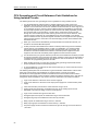
The following items are CPU grounding and circuit guidelines for using isolated circuits:
-
You should identify the reference point (0 voltage reference) for each circuit in the
installation, and the points at which circuits with possibly different references can connect
together. Such connections can result in unwanted current flows that can cause logic errors
or can damage circuits. A common cause of different reference potentials is grounds that
are physically separated by long distances. When devices with widely separated grounds
are connected with a communication or sensor cable, unexpected currents can flow
through the circuit created by the cable and the ground. Even over short distances, load
currents of heavy machinery can cause differences in ground potential or can directly
induce unwanted currents by electromagnetic induction. Power supplies that are improperly
referenced with respect to each other can cause damaging currents to flow between their
associated circuits.
-
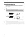
When you connect CPUs with different ground potentials to the same PPI network, you
should use an isolated RS-485 repeater.
-
S7-200 products include isolation boundaries at certain points to help prevent unwanted
current flows in your installation. When you plan your installation, you should consider
where these isolation boundaries are provided, and where they are not provided. You
should also consider the isolation boundaries in associated power supplies and other
equipment, and where all associated power supplies have their reference points.
-
You should choose your ground reference points and use the isolation boundaries provided
to interrupt unneeded circuit loops that could allow unwanted currents to flow. Remember to
consider temporary connections which may introduce a new circuit reference, such as the
connection of a programming device to the CPU.
-
When locating grounds, you must also consider safety grounding requirements and the
proper operation of protective interrupting devices.
-
In most installations, you will have the best noise immunity if you connect the CPU sensor
supply M terminal to ground.
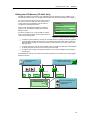
The following descriptions are an introduction to general isolation characteristics of the S7-200
family, but some features may be different on specific products. Consult your product
specifications in the appropriate manual for information about which circuits include isolation
boundaries and the ratings of the boundaries. Isolation boundaries rated less than 1,500 VAC are
designed as functional isolation only, and should not be depended on as safety boundaries.
94
-
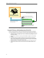
Logic circuit reference is the same as DC sensor supply M.
-
Logic circuit reference is the same as the input power supply M on a CPU with DC power
supply.
-
CPU communication ports have the same reference as logic circuit.
-
Analog inputs and outputs are not isolated from logic circuit. Analog inputs are full
differential to provide low voltage common mode rejection.
-
Logic circuit is isolated from ground to 500 VAC.
-
DC digital inputs and outputs are isolated from logic circuit to 500 VAC.
-
DC digital I/O groups are isolated from each other by 500 VAC.
-
Relay outputs are isolated from logic circuit to 1,500 VAC.
-
Relay output groups are isolated from each other by 1,500 VAC.
-
AC power supply line and neutral are isolated from ground, the logic circuit, and all I/O to
1,500 VAC.