1
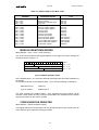
29/01/93
V495 User Manual
3. OPERATING MODES
The output of the single unit Independently from the selected operating mode can be
selected to be valid in one of the following output modes:
STROBED
the leading edge of the external or internally software generated
STROBE signal freezes the inputs' configuration of the section and
the relevant configuration of the outputs is then placed on the output
connector; the output drivers are always in reset mode except during
the STROBE signal. If the input configuration changes during the
STROBE interval, the variations do not affect the output configuration
freezed at the leading edge time1. The output is then valid ONLY
during the STROBE signal width.
SHAPED
the unit works as above except that the output width is fixed by via a
front panel trimmer per section in a range that can vary from 12 ns to
65 ns.
NORMAL
the output varies all the time according to the input configuration.
LOOK-UP TABLE
The module V495 houses 2 independent sections, labelled A and B, with 8 inputs and
8 outputs.
Before using the unit, the 256 RAM locations of each section must be programmed to
keep the desired output bit configuration according to the logic function which has to be
realized. The front panel three position switch of each section has to be set according
to the desired output mode.
PATTERN GENERATOR
The module can be a two section PATTERN GENERATOR. The input connector of
each section is then replaced by an ADDRESS REGISTER which sequentially drives
the RAM address bus starting from the first programmable via VME.
The output configurations are placed on the output connectors at the rate fixed by the
VME system clock or by an external clock fed to the relevant CLK input connector.
The operations of the V495 as PATTERN GENERATOR are fully software
programmable; via VME it is possible:
to fill the RAM locations with the desired configurations;
to program the RAM starting address for the sequence of the patterns;
to select the internal VME system clock, 16 MHz, or the external clock source;
to select between two different subsets of operations:
1Due to internal delays the inputs are freezed after 5 ns from the STROBE leading
edge; the outputs are valid after 13 ns from the the same leading edge and valid for a
time equal to the STROBE width.In any case the output validity is signalled by the
SYNC trailing edge.
8