1
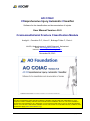
AO COIAC COmprehensive Injury Automatic Classifier Software for the classification and documentation of injuries User Manual Version 4.0.0 Craniomaxillofacial Fracture Classification Module Audigé L., Cornelius P.C., Kunz C., Buitrago-Tellez C., Prein J. AOCID, Stettbachstrasse 6, 8600 Dübendorf, Switzerland Email: [email protected] Internet: www.aofoundation.org/aocoiac November 28, 2013 Important Note and Disclaimer: We cannot guarantee 100% that this software is problem-free and will work adequately on your computer. Please carefully read this user manual before installation and use. The AO Foundation cannot take responsibility for any damages or inconveniences that may occur by using this software version. For use of the AO COIAC software and its manual the AO Foundation terms, conditions and disclaimers apply (www.aofoundation.org) 28/11/2013 page 1/43 Table of contents 1. 2. 3. Introduction ................................................................................................................... 3 CMF classification module............................................................................................. 3 Mandibular fractures (91) .............................................................................................. 5 3.1. Level-1 system ....................................................................................................... 5 3.1. Level-2 system ....................................................................................................... 6 3.1.1. Panoramic view ............................................................................................... 6 3.1.1. Dentition .......................................................................................................... 8 3.1.2. Mandibular atrophy ....................................................................................... 10 3.1.3. Fracture location ........................................................................................... 11 3.1. Level-3 system ..................................................................................................... 13 3.1.1. Angle/Ramus, Body, Symphysis/Parasymphysis........................................... 14 3.1.1. Condylar Process .......................................................................................... 16 3.1. Fracture code, illustrations and Surgery Reference .............................................. 20 4. Fractures of the cranium ............................................................................................. 22 4.1. General overview ................................................................................................. 22 4.1.1. Level-1 system .............................................................................................. 22 4.1.2. Level-2 system .............................................................................................. 22 4.1.3. Level-3 system .............................................................................................. 23 4.2. Fractures of the midface (92) ............................................................................... 25 4.2.1. Classification menu windows ........................................................................ 26 4.2.1. Dentition and atrophy .................................................................................... 27 4.2.1. Alveolar process fractures ............................................................................. 27 4.2.2. Fracture patterns ........................................................................................... 29 4.2.1. Fracture morphology ..................................................................................... 30 4.1. Fractures of the skull base (93) ............................................................................ 36 4.1.1. Endocranial surface ...................................................................................... 36 4.1.1. Exocranial surface......................................................................................... 38 4.2. Fractures of the cranial vault (94) ......................................................................... 39 4.3. Fracture code and Surgery Reference ................................................................. 41 5. Acknowledgements ..................................................................................................... 42 6. References.................................................................................................................. 43 28/11/2013 page 2/43 1. Introduction The AO Foundation developed the software named AO COIAC (AO COmprehensive Injury Automatic Classifier) to facilitate the diagnosis, coding and documentation of injuries. This software version includes the long bone fracture classification (adult and paediatric) as well as the new AOCMF fracture classification modules. The AOCMF Classification Group developed a hierarchical 3-level craniomaxillofacial fracture classification system (1). The fundamental Level-1 distinguishes 4 major anatomical units including the mandible (code 91), midface (92), skull base (93) and cranial vault (94); Level-2 relates to the location of the fractures within defined topographical regions within each units; Level-3 relates to fracture morphology in these regions regarding fragmentation, displacement, and bone defects, as well as the involvement of specific anatomical structures. An introduction to the CMF classification module in AO COIAC has been presented (2). This manual highlights in more details its functionality. The general features of the AO COIAC software for classification and documentation are presented in a separate main manual. Important note = this manual do not present and explain the CMF classification system in details. The user should read the related tutorials published in a special issue of the Journal of Cranio-maxillofacial Trauma and Reconstruction (CMTR). Reference to the specific tutorials will be made within appropriate sections of this manual. The use of AOCOIAC for CMF fracture classification should be referenced as follows: Audigé L., Cornelius P.C., Kunz C., Buitrago-Tellez C., Prein J. (2013) AO COIAC COmprehensive Injury Automatic Classifier Software: User Manual Version 4.0.0 Craniomaxillofacial Fracture Classification Module, AO Foundation, Davos, Switzerland, 43 pages or Audigé L., Cornelius P.C., Kunz C., Buitrago-Tellez C., Neff A., Di Ieva A., Rudderman R., Frodel J., Prein J. (2014) AO classification system for fractures of the craniomaxillofaxial skeleton: software solution for documentation, Craniomaxillofacial Trauma and Reconstruction, in press 2. CMF classification module The CMF classification module can be accessed by double-click on the cranium of the adult skeleton either using the training tab (no classification data will be saved) (Figure 1) or using the fracture tab (for case documentation after registering patient demographics and trauma event). It is organized and presented to facilitate fracture coding according to any of the 3 levels of the classification (Figure 2). 28/11/2013 page 3/43 Figure 1 Figure 2 28/11/2013 page 4/43 On the top-left corner of the windows interface, the skull is presented for Level-1 classification; on the left column and top row, respectively, illustrations of the mandible and cranium give access to Level-2 and Level-3 classifications. By mouse-click on the desired illustrative view, a corresponding larger illustration is presented in the central window with delimitations of Level-2 regions or Level-3 subregions depending on the selected view. On the top row a panoramic illustration of the zygomas, orbits and nose delimits Level-3 subregions for the cranium. Similarly on the left column, an illustration of both condylar processes is used for Level-3 classification of condylar process subregions (head, neck and base). Fracture classification may be implemented directly on the selected illustrations or using the side table on the right-side of the screen window. 3. Mandibular fractures (91) 3.1. Level-1 system Identification of patients with mandibular fractures can be implemented on the Level-1 system from the skull window interface (Figure 3). The mandible is highlighted in blue and the code 91 is shown on the bottom right window. Figure 3 28/11/2013 page 5/43 3.1. Level-2 system The defined regions for the mandible are described in details by Cornelius et al (3) and illustrated in Figure 4. Figure 4 Reproduced from Cornelius et al (3). Four transitional zones between adjacent symphysis and body subdivisions (1 = anterior transitional zones), and between adjacent body and angle/ramus subdivisions (2 = posterior transitional zones) are defined and the rules for classification of fracture location and continuity across subdivisions are applied within AO COIAC. 3.1.1. Panoramic view To classify mandibular fractures according to the Level-2 system, the panoramic view of the mandible should be selected by clicking on the corresponding view on the left column (Figure 3). This view should be presented in the central window for classification. Note = we recommend to switch the view from color to black and white by clicking on the related icon on the tool bar 28/11/2013 page 6/43 Figure 5 To support the classification process, the mouse pointer can be transformed into a pen by double-click within the central window anywhere outside the illustration (and vise-versa); the pen can be used to draw the fracture line(s)(see the main user manual). The regions or subregions corresponding to these drawn lines are selected as fractured, in accordance with rules and definitions (e.g. location inside the transition zones of the mandible)(Figure 6). Figure 6 28/11/2013 page 7/43 A double-click with the mouse pointer on a region or subregion of interest opens up menu windows tabulating respective Level-2 and Level-3 descriptors to specify the fracture in greater detail (Figure 7). Figure 7 Important note = When selecting one or more Level-2 regions as fractured, all other regions or subregions that are not explicitly categorized as fractured are considered as not fractured by default. The same principle applies to the classification of Level-3 subregions. 3.1.1. Dentition The dentition status can be specified from the menu windows that can be opened by double mouse-click on the respective tooth or teeth. The classification categories are illustrated in Figure 8 along with their graphical presentation on the panoramic view. The tooth status can be set as "undetermined" as shown for tooth 42. When a series of teeth needs to be specified as "absent (before trauma)" to document partial or full edentualism, it is more convenient to use the side table on the right-side of the AO COIAC window. This can be achieved by checking the box in front of the respective tooth numbers (Figure 9). 28/11/2013 page 8/43 Figure 8 Figure 9 28/11/2013 page 9/43 3.1.2. Mandibular atrophy The level of mandibular atrophy can be specified separately for the Body (B) and Symphysis/Parasymphisis (S) regions, as soon as one tooth is absent (before trauma) in the concerned region. With no teeth missing, the classification dialogue window (Figure 7) for mandibular atrophy remains inactive. According to the level of atrophy specified, part of the concerned region is masked in white for illustration. Figure 10 28/11/2013 page 10/43 3.1.3. Fracture location Alveolar fractures Alveolar fractures can be specified from the menu window accessible by double-click on the respective tooth root. The fractured alveolar bone is highlighted in violet (Figure 11). Figure 11 When an alveolar process fracture involves several contiguous teeth, each involved tooth root should be classified similarly. It is more convenient to use the side table on the rightside of the AO COIAC window. This can be achieved by checking the box in front of the respective tooth numbers (Figure 12). Figure 12 28/11/2013 page 11/43 Fractured regions Regions potentially involved by the fracture scenario that are difficult to analyze or unevaluable (e.g. due to lack or shortages in diagnostic imaging) can be indicated as "undetermined". These regions are marked with a grid pattern (Figure 13) Figure 13 The Level-2 classification involves specifying the fractured regions. This is achieved by selecting "Fractured" on the respective menu windows. By clicking outside these windows, they will close and the involved region(s) will be highlighter in blue (Figure 14). To reverse this selection either use the undo icon available on the icon bar , or select "Not fractured" within the menu window that is opened following a new double-click on the concerned region. Figure 14 28/11/2013 page 12/43 Fractures of the Angle/Ramus (A), Body (B) and Symphysis/Parasymphysis (S) can be located within their respective region – they are described as "confined" - or extent to their adjoining region – they are the described as "not confined". This classification is implemented within the respective Level-2 menu windows. Note = Condylar Process (P) and Coronoid (C) regions are not concerned in this specification. If one of the three regions A, B and S is coded with a "not confined" fracture, one of its adjoining regions must be coded similarly (Figure 15). Figure 15 3.1. Level-3 system The Level-3 system is used to specify items related to fracture morphology. They are available for coding using the menu windows (Figure 7). In addition for fractures of the Condylar Process (P), a new illustration presenting the two processes in postero-anterior and lateral views is used (Figure 16). This view is accessible by clicking on its smaller format on the left column (red arrow). There is no Level-3 item for the Coronoid (C). Note = the classification process may be restricted to the Level-1 or Level-2, not taking the features of fracture morphology within Level-3 into account. If Level-3 is applied, it is reasonable that all affected regions are classified uniformly at this level to comply with a clear and concise layout. Marking of a Level-3 descriptor such as the fragmentation grade in a region or subregion, however, will automatically retroactivate the Level-1 and Level-2 classification and can be used as a shortcut and timesaver in the coding process. 28/11/2013 page 13/43 Figure 16 3.1.1. Angle/Ramus, Body, Symphysis/Parasymphysis The Level-3 system for the mandible regions A, B and S is described in details by Cornelius et al (4). Fragmentation Fractured A, B and S regions can be classified according to the level of fragmentation in 3 classes. The definition of these classes is the same for B and S regions however differ for A regions. The user should consult the relevant tutorial to find these definitions. A color scheme is used to represent the gradation of fragmentation (Figure 17): Yellow = not fragmented Orange = minor fragmentation Red = major fragmentation 28/11/2013 page 14/43 Figure 17 Bone loss Bone loss can be specified using the diagnose windows just below the fragmentation. Regions identified with bone loss (d = defect) are marked with additional stripes superimposed to the color scheme of fragmentation (Figure 18). Figure 18 28/11/2013 page 15/43 3.1.1. Condylar Process The Level-3 system for the condylar process region P is described in details by Neff et al (5). Subregions Fractures of the condylar process (P) can be specified according to their course within the three subregions Head (H), Neck (N) and Base (B) which are illustrated in the detailed Level-3 view (Figure 19). It is possible to specify separate fracture within each of the three subregions. Figure 19 The detailed Level-3 view can be accessed also from the bottom link "Open…" within the menu window presented in the Figure 19 above. The subregions can be classified as fractured directly from this detailed view by clicking on the respective subregions and selecting "fractured" on the associated menu window (Figure 20). 28/11/2013 page 16/43 Figure 20 Fractures of the Condylar Head (H) can be further classified according to the location of the fracture line(s) medial to the pole zone (m), or within or lateral to it (p) (Figure 21). When only the location of a fracture is specified, and not its fragmentation, the involved subregions are highlighted in blue. Figure 21 28/11/2013 page 17/43 Fragmentation For each subregion, the level of fragmentation is specified in one of three categories as for the other A, B and S regions, however using specific category definitions. The relevant tutorial paper should be consulted for more details (5). The same color scheme is used to represent the gradation of fragmentation (Figure 22): Yellow = not fragmented Orange = minor fragmentation Red = major fragmentation Figure 22 Displacement Displacement parameters are related to: Injuries the Condylar Process (P) as a whole, or Fractures within the specific subregions. In the first situation their documentation is done using the menu window from the panoramic view (Figure 19); they include: The position of the condylar head with regard to the fossa The position of the ramus stump with regard to the fossa Distortion of the condylar head Change of the ramus height 28/11/2013 page 18/43 In the second situation their documentation is done using the respective menu window of the subregions from the detailed view (Figure 20); they include: Head: o Loss of vertical apposition Neck and Base: o Sidewards displacement o Angulation o Override / Shortening The direction of displacement for condylar process fractures can also be specified according to two parameters related to antero-posterior and medio-lateral direction, for each of the following displacement parameters: Position of the condylar head with regard to the fossa Position of the ramus stump with regard to the fossa Sidewards displacement of neck and Base fractures Angulation of neck and Base fractures This classification is however not performed using the menu windows but via the entry table on the right side of the screen window after selecting the Level-3 tab (Figure 23). Figure 23 28/11/2013 page 19/43 3.1. Fracture code, illustrations and Surgery Reference After completion of the classification, the fracture code is presented within the bottom-right screen window (Figure 24). The codes can be copied to the computer clipboard following double-click of the mouse over them. Figure 24 Mandible 91 P.B0.m P (right) N0 The related illustrations can be copied or saved electronically for use in publications and presentations using the icon bar or Direct access to the AOCMF Surgery Reference portal (Figure 25) at a remaining basic level of the classification is provided by selecting the icon "AO Surg. Ref." on the right of the fracture code (Figure 24). 28/11/2013 page 20/43 Figure 25 28/11/2013 page 21/43 4. Fractures of the cranium 4.1. General overview 4.1.1. Level-1 system Identification of patients with fractures of the midface, skull base and cranial vault can be implemented on the Level-1 system from the skull window interface (Figure 26). The respective fractured area is highlighted in blue. Figure 26 4.1.2. Level-2 system The Level-2 system allows specifying the fracture location within predefined regions. It is presented and explained in details in the corresponding tutorials for the midface (6) and skull base / cranial vault (7). To classify fractures of the cranium according to the Level-2 system, the skull must be selected by clicking on any appropriate view on the top row, except the detailed view of the orbits, zygoma and nose on its right-hand side. The selected view should be presented in the central window for classification (e.g. the frontal view in Figure 27). 28/11/2013 page 22/43 Figure 27 The classification process is similar to that presented for the mandible. By double-click on any delimited bone region a specific dialogue widow is presented for classification including Level-2 as well as some Level-3 parameters (e.g. for the Zygoma in Figure 28). 4.1.3. Level-3 system The Level-3 system allows classifying fractures according to relevant morphological characteristics. Level-3 parameters pertinent to the involved region(s) are presented for classification within the menu windows mentioned above (Figure 28). Other Level-3 parameters are related to subregions delimited within the detailed view of the zygomas, orbits and nose that is accessed by double click on the right-hand side icon on the top row (Figure 29 in color scheme). 28/11/2013 page 23/43 Figure 28 Figure 29 28/11/2013 page 24/43 4.2. Fractures of the midface (92) The defined regions for the midface are described in details by Kunz et al (6) and illustrated in Figure 30. Figure 30 a b c d UCM = Upper Central Midface - Nasal skeleton including bone and nasofrontal maxilla; ICM = Intermediate Central Midface - Parapiriform maxilla and infraorbital maxilla; LCM = Lower Central Midface - Maxillary bodies including infrazygomatic maxilla; Z = Zygoma / zygomatic arch. Reproduced from Kunz et al (6) 28/11/2013 page 25/43 4.2.1. Classification menu windows The classification menu windows specific to the central midface regions (LCM, ICM and UCM) are presented in Figure 31, and to the zygoma, pterygoid process and palate regions in Figure 32. Figure 31 28/11/2013 page 26/43 Figure 32 The classification menu windows specific to the orbit regions (orbital walls and apex) are presented in Figure 33. At the bottom of all menu windows, except that of the Lower Central Midface (LCM) and Pterygoid process, an option allows accessing directly the detailed panoramic view of subregions (Figure 29) by clicking on "Open…" 4.2.1. Dentition and atrophy The dentition status at the lower central midface can be specified similarly to that of the mandible. The user should refer to that section (3.1.1) for more details. A level of atrophy can be recorded in one of three categories (see LCM in Figure 31) when at least one tooth is set as absent before trauma (see section 3.1.2). 4.2.1. Alveolar process fractures Alveolar process fractures can be documented at the lower central midface similarly to those in the mandible (see section 3.1.3) 28/11/2013 page 27/43 Figure 33 28/11/2013 page 28/43 4.2.2. Fracture patterns Fracture patterns are part of the Level-2 system of the midface. Three fracture patterns can be specified from the menu windows depending on the involved regions: Le Fort (LF) type I, II and III Zygoma en bloc (ZEB) Naso-orbito-ethmoidal (NOE) While the NOE pattern is central, both Le Fort and ZEB patterns can be specified separately on either or both sides. On any side the Le Fort I, II and III patterns are exclusive, i.e. they cannot be combined. The NOE pattern can be combined with ZEB and/or Le Fort I patterns. The ZEB pattern can be combined with Le Fort II or Le Fort I (with or without NOE) patterns The regions involved in any specified pattern or associated patterns are highlighted in purple, such as bilateral Le Fort patterns (Figure 34). NOE and Zygoma en bloc patterns are also illustrated within the detailed panoramic view. Figure 34 Le Fort I Le Fort II Le Fort III NOE and Zygoma en bloc Le Fort I and II 28/11/2013 page 29/43 4.2.1. Fracture morphology Fracture morphology is specified by Level-3 parameters that are described in the tutorial papers by Cornelius et al (midface)(8) and by Kunz et al (orbits)(9), respectively. Central midface and Zygoma Fractures in the LCM, ICM, UCM and Zygoma regions can be described according to three parameters: Fragmentation: 0 = Not fragmented / 1 = Fragmented Displacement: 0 = Not displaced / 1 = Displaced Bone loss: d = bone loss (defect). Regions with non-fragmented and fragmented fracture are coloured in yellow and orange, respectively (Figure 35). Those diagnosed with bone loss (d) are marked with additional stripes superimposed to the color scheme of fragmentation as illustrated for the mandible (Figure 18). Fracture displacement is not represented graphically however, although recorded in the AO COIAC database when documenting patients. Figure 35 28/11/2013 page 30/43 The regions ICM, UCM and Zygoma include part of the orbital rims that can be selected within the respective classification menu windows when fractured. The affected rims are darkened when selected (Figure 35): ICM : i = inferior rim UCM : m = medial rim (left / right) Zygoma : i = inferior rim, and l = lateral rim The Pterygoid process can be classified as being separated vertically from the maxilla (orange colour) or not (yellow colour) as the only Level-3 classification parameter (Figure 32 and Figure 36). Figure 36 A fractured palate can be further described with regard to the course of the fracture line(s), as well the occurrence of bone loss (Figure 37). Figure 37 28/11/2013 page 31/43 The detailed panoramic view of the subregions of the midface offers a mapping of the subregions for more refined classification. Subregions of the UCM include the medial orbital rims (presented in a subsequent section) and the nasal bone and the upper nasal septum. Fractures of the nasal bone can be specified as fragmented (highlighted in orange) or not fragmented (highlighted in yellow), displaced or not displaced, as well as with bone loss (d = defect)(Figure 38). The lower nasal septum belongs to the LCM; the anterior antral wall and the highlighted part of the area of zygomatico-maxillary crest belong to the ICM. Figure 38 28/11/2013 page 32/43 Subregions of the Zygoma include an area of the zygomatico-maxillary crest, the zygomatic body, both being involved in the Zygoma en bloc pattern, as well as the zygomatic arch and its temporal origin (Figure 39). Zygomatic arch can have single (highlighted in yellow) or multiple (highlighted in orange) fractures, and the fracture(s) can be further described as displaced or not. Other subregions of the zygoma are presented in the following section along with other subregions of the orbits. Figure 39 Orbit As presented in the classification menu windows in Figure 33, fractures within orbital regions (walls and apex) can be described as being displaced or not. Displacement is not illustrated on the graphical display. In addition specific orbital structures can be selected as involved or not. If a fracture pattern is selected (Le Fort III, NOE or Zygoma en bloc), the displacement parameter can be specified, however this attribute then concerns the whole pattern and not just the concerned region (Figure 40). In addition, no structures can be selected within the regions involved in the fracture pattern. 28/11/2013 page 33/43 Figure 40 The detailed panoramic view of the subregions of the midface offers a mapping of the subregions for more refined classification (Figure 41). Orbital rims can be described similarly to the midface regions LCM, ICM, UCM and Zygoma (Figure 35) according to fragmentation (Not fragmented / Fragmented), displacement (Not displaced / Displaced) and bone loss (defect). Regions with non-fragmented and fragmented fracture are coloured in yellow and orange, respectively. Those diagnosed with bone loss (d) are marked with additional stripes superimposed to the color scheme of fragmentation. The orbital walls can be specified as "Linear frature (Fx.)", "Lamellar Fx." or "Defect Fx." which are highlighted in yellow, orange and red, respectively, after classification. 28/11/2013 page 34/43 While a linear fracture can be further specified as non-displaced or displaced, a lamellar fracture and a defect fracture are always classified as displaced. The three subregions of the apex, can be specified as non-displaced or displaced. The ZSS and ZFS subregions can be specified as fractured as shown in Figure 41. Figure 41 28/11/2013 page 35/43 4.1. Fractures of the skull base (93) The defined regions for the skull base are described in details by di Ieva et al (7) and illustrated in Figure 42 considering the endocranial (a) and exocranial (b) surfaces. Figure 42 a B A = Anterior skull base; Ca = Central anterior; M = Middle; Cm = Central middle; P = Posterior; Cp = Central posterior; S = Sphenoid bone; T = Temporal bone; O = Occipital bone. ; P = Parietal bone (cranial vault) Reproduced from di Ieva et al (7) 4.1.1. Endocranial surface The classification menu windows specific to the endocranial surface.of the skull base are presented in Figure 43. Each of the 9 regions can be classified according to fragmentation in 2 classes (not fragmented highlighted in yellow / fragmented highlighted in orange) and displacement in 3 classes (non-displaced / displaced but not depressed / depressed). In addition specific structures can be selected as involved (fractured or opacification) within the central anterior skull base (ethmoid sinus on both sides, cribriform, frontal sinus) and central middle skull base (sphenoid sinus). 28/11/2013 page 36/43 Figure 43 28/11/2013 page 37/43 4.1.1. Exocranial surface The classification menu windows specific to the exocranial surface.of the skull base are presented in Figure 44. Each of the 6 regions S, T and O can be classified according to fragmentation in 2 classes (not fragmented highlighted in yellow / fragmented highlighted in orange) and displacement in 3 classes (non-displaced / displaced but not depressed / depressed) similarly to the endocranial surface. In addition bone loss (d = defect) can be specified. Glenoid fossa fractures can be noted as involving the sphenoid and/or the temporal bone, and fractures of the occipital condyles are noted within the occipital region Figure 44 28/11/2013 page 38/43 4.2. Fractures of the cranial vault (94) The defined regions for the cranial vault are described in details by Di Ieva et al (7) and illustrated in Figure 45. Figure 45 a b F = Frontal bone; T = Temporal bone; P = Parietal bone; O = Occipital bone; S = Sphenoid bone (skull base). Regions labelled in red are from the skull base. Reproduced from di Ieva et al (7) The classification menu windows specific to the cranial vault are presented in Figure 46. Each of the 4 regions F, P, T and O can be classified according to fragmentation in 2 classes (not fragmented highlighted in yellow / fragmented highlighted in orange) and displacement in 3 classes (non-displaced / displaced but not depressed / depressed). In addition bone loss (d = defect) can be specified and highlighted with stripes over the color scheme. Involving the frontal bone, the superior and part of the medial orbital rims can be selected as being fractured; their detailed classification can be further performed from the detailed view that can be accessible directly from within the menu window of the frontal bone (click on "Open…" just below "Access to more detail view (see Figure 41). Note = The classification of subregions within the detailed view is not initiated by fracture classification within the region (the only exception is for the zygoma en bloc fracture pattern as described in section 4.2.2). 28/11/2013 page 39/43 Figure 46 28/11/2013 page 40/43 4.3. Fracture code and Surgery Reference After completion of the classification, the fracture code is presented within the bottom-right screen window (Figure 47). The codes can be copied to the computer clipboard following double-click of the mouse over them. Figure 47 Mandible P (right) Midface O (right) O (left) 91 P.A0.m.B0 B0 92 I0i.L0.Pt0.Oi.m.Oil.Pt0.L0.I0i.Z0li R(i).W1(i) R(li).W1(li) Direct access to the AOCMF Surgery Reference portal at a remaining basic level of the classification is provided by selecting the appropriate icon "AO Surg. Ref." on the right of the fracture code. 28/11/2013 page 41/43 5. Acknowledgements This software project was funded by the AO Foundation, AOTrauma and AOCMF through the activities of the AO Classification Supervisory Committee and its Classification Groups, and implemented by AO Clinical Investigation and Documentation. The Pediatric Classification Group (PACG) coordinated and supervised the development of this AO COIAC database extension. Software core project team: Laurent Audigé (CH) Dirk Sauter (DE) Jim Kellam (USA) Theddy Slongo (CH) Peter Cornelius (DE) Julie Agel (USA) AOCID Methodological expertise Programmer, Ing. Büro Marschelke, Reichenau DE Medical expertise – Module long bones for adults Medical expertise – Module long bones for children Medical expertise – CMF Module OTA Coding and Classification Committee Craniomaxillofacial Classification Group (CMCG) Current core group J Prein (CH)(Chairman) P Cornelius (DE) L Audigé (CH) C Kunz (CH) J Frodel (USA) R Rudderman (USA) C Buitrago-Tellez (CH) Subgroups Anterior Skull Base B Kellman (USA) K Shumrick (USA) C Matula (AU) A di Ieva (AU) Condylar Process M Rasse (AU) A Neff (DE) P Cornelius (DE) Other contributors M Ehrenfeld (DE) J Hirsch (SE) A Sugar (UK) B Alpert (USA) B Strong (USA) Ch Lindqvist (FI) P Louis (USA) The software programming is implemented by: D Sauter , H Marschelke Ingenieurbüro Marschelke Strandbadstrasse 6 78479 Reichenau Germany AO COIAC is supported by: The Orthopedic Trauma Association (OTA) Classification, Database and Outcome Committee 28/11/2013 page 42/43 6. References (1) Audigé L, Cornelius CP, Di Ieva A, Prein J, CMF Classification Group. Introduction to the first AO classification system for fractures of the craniomaxillofaxial skeleton: rationale, methodological background, developmental process and objectives. Craniomaxillofacial Trauma & Reconstruction 2014;in press. (2) Audigé L, Cornelius CP, Buitrago-Téllez CH, Kunz C, Neff A, Di Ieva A, Ruddermann R, Frodel J, Prein J. AO classification system for fractures of the craniomaxillofaxial skeleton: software solution for documentation. Craniomaxillofacial Trauma & Reconstruction 2014;in press. (3) Cornelius CP, Audigé L, Kunz C, Ruddermann R, Buitrago-Téllez CH, Frodel J, Prein J. AO classification system for fractures of the craniomaxillofaxial skeleton: Level 2 mandible fractures. Craniomaxillofacial Trauma & Reconstruction 2014;in press. (4) Cornelius CP, Audigé L, Kunz C, Ruddermann R, Buitrago-Téllez CH, Prein J. AO classification system for fractures of the craniomaxillofaxial skeleton: Level 3 mandible fractures. Craniomaxillofacial Trauma & Reconstruction 2014;in press. (5) Neff A, Audigé L, Rasse M, Kolk A, Dalla Torre D, Cornelius CP. AO classification system for fractures of the craniomaxillofaxial skeleton: Level 3 condylar process fractures. Craniomaxillofacial Trauma & Reconstruction 2014;in press. (6) Kunz C, Cornelius CP, Prein J, Buitrago-Téllez CH, Frodel J, Ruddermann R, Audigé L. AO classification system for fractures of the craniomaxillofaxial skeleton: Level 2 midface fractures. Craniomaxillofacial Trauma & Reconstruction 2014;in press. (7) Di Ieva A, Audigé L, Kellman RM, Shumrick KA, Ringl H, Matula C. AO classification system for fractures of the craniomaxillofaxial skeleton: Level 3 skull base and cranial vault fracture. Craniomaxillofacial Trauma & Reconstruction 2014;in press. (8) Cornelius CP, Audigé L, Kunz C, Ruddermann R, Buitrago-Téllez CH, Frodel J, Prein J. AO classification system for fractures of the craniomaxillofaxial skeleton: Level 3 midface fractures. Craniomaxillofacial Trauma & Reconstruction 2014;in press. (9) Kunz C, Cornelius CP, Audigé L, Ruddermann R, Buitrago-Téllez CH, Prein J. AO classification system for fractures of the craniomaxillofaxial skeleton: Level 3 orbital fractures. Craniomaxillofacial Trauma & Reconstruction 2014;in press. 28/11/2013 page 43/43