1
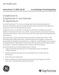
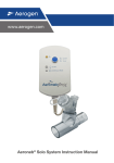
Virtual Implant Placement 2.1
catalog & surgical manual
99.2%
average
implant
success
rate1
BioHorizons is one of the fastest growing companies in the dental implant industry. Our comprehensive
portfolio of dental implants and biologics products is evidence-based and scientifically-proven. From the
launch of the External implant system (Maestro) in 1997, to the introduction of the Tapered Internal implant
incorporating Laser-Lok® technology in 2007, BioHorizons has continued to provide clinicians unique products
supported by university based research.
SCIENCE
global
leader for
biologic
based
solutions
BioHorizons uses science and
innovation to create unique products
with proven surgical and esthetic results.
INNOVATION
Our advanced implant technologies,
biologic products and computer guided
surgery software have made BioHorizons
a leading dental implant company.
products
sold
in 85
markets
SERVICE
BioHorizons understands the
importance of providing excellent
service. Our global network of
professional representatives and our
highly trained customer care support
team are well-equipped to meet the
needs of patients and clinicians.
Company Overview
Virtual Implant Placement 2.1
VIP
Applications
System Requirements
VIP Components
VIP Software
Pilot Drill Set
Individual Pilot Drill Instruments
Radiographic Appliances (CT Scan Appliance & Compu-Quick)
Pilot Compu-Guide
Collaterals
Disclaimer
CT Planning
CT Scan Appliance
Compu-Quick
CT Scan
CT Scan Protocol
VIP Planning
VIP Interface
DICOM Converter
Draw Nerve
Implant Planning
Submit VIP Treatment Plan for Pilot Compu-Guide
Order On-line
Additional Features
Measuring Tools
Virtual Teeth
Parallel Implants
Preferences
VIP Download
Pilot Compu-Guide
Pilot Compu-Guide
Pilot Drill Set
Important Considerations
Pilot Drill Set Cleaning
Pilot Compu-Guide Pre-Operative
Pilot Compu-Guide Surgical Procedure
Icon Legend & References
Warranty Information & Product Terms
1
2-3
2
3
3
4-5
4
4
4
5
5
6
7
8-10
8
9
9
10
11-16
11
12-13
14
15-16
16
17
18-20
18-19
19
20
20
20
21-23
21
22
22
22
23
23
24
25
VIRTUAL IMPLANT PLACEMENT
VIP
Virtual Implant Placement (VIP) treatment planning software was developed by a team of clinicians to
provide a user-friendly, virtual treatment planning solution that reduces clinical challenges and enhances
post-operative outcomes.
•
•
•
•
•
Self-processing DICOM converter
Demo version or Case Viewer available on BioHorizons website
Open software platform implant compatibility
Improves communication between clinician and patient Use virtual treatment plan to create Compu-Guide* surgical templates
Step 1
Upper and lower diagnostic casts and CT Scan Appliance Prescription are sent to an
approved BioHorizons Partner Laboratory
• Download CT Scan Appliance Prescription from www.biohorizons.com
• View Partner Laboratories list at www.biohorizons.com
If Compu-Quick Scan Appliance is used, refer to Step 3
Step 2
Partner Laboratory fabricates CT Scan Appliance and sends to clinician
Step 3
Patient wears Scan Appliance during CT Scan
• Download CT Scanning Protocol from www.biohorizons.com
Step 4
Clinician receives DICOM data from scan center, begins self-processing and
virtually treatment plans the case with VIP
Step 5
If a Compu-Guide surgical template is desired: Scan Appliance, VIP treatment plan,
DICOM data and Pilot Compu-Guide Prescription are sent to BioHorizons VIP
Laboratory
• Download Compu-Guide Prescription from www.biohorizons.com
Step 6
BioHorizons VIP Laboratory converts the Scan Appliance into a Compu-Guide
surgical template using the virtual VIP treatment plan
Step 7
Clinician performs procedure using the Compu-Guide surgical template
Clinician
Partner
Laboratory
BioHorizons
* The submitted VIP treatment plan establishes Drill Sleeve placement for the initial 2mm pilot osteotomy including implant
location, depth, and angulation. The Drill Sleeve is located above the level of hard and soft tissue. The planned osteotomy
location can be reviewed by placing the Compu-Guide surgical template on the respective diagnostic stone model.
2
VIRTUAL IMPLANT PLACEMENT
Applications
The VIP treatment plan can be transferred to the Pilot Compu-Guide for the following implant treatment plans:
• Partially edentulous single implant placement
• Immediate extraction/single implant placement
• Partially edentulous multiple implant placement
• Fully edentulous multiple implant placement
System Requirements
Minimal System Requirements
Operating system
Windows® XP
Processor
Pentium® III CPU, 500 MHz
Hard drive
1 GB of free hard drive disk space
Internal memory
256 MB
Monitor
15” monitor
Mouse
Windows supported mouse
Internet
Windows Internet Explorer® 6 or 7
An email application and a mouse with a scroll wheel are recommended.
Installation of VIP is a Demo version until a software license is requested and applied. The software license
can be requested via Internet connection by navigating to Tools > License and submitting the requested
information to [email protected]. Customer Care can also assist with providing a software
license for VIP.
3
VIP COMPONENTS
VIP Software
VIP 2.1 Software
Includes (2) software licenses
VIP Software Upgrade
Upgrade existing VIP to current version
VIP License
Purchase additional VIP licenses
Virtual Implant Placement 2.1
VIP
VIP Download
Download a Demo Version or Case Viewer at www.biohorizons.com
Pilot Drill Set
122-000
2.0mm CGS Pilot Drill Set
Includes 2.0 x 17, 21, 24, and 28mm Pilot Drills. Pilot Drills are used
with the Pilot Compu-Guide (see page 21). The Drilling Report that
is provided with the Pilot Compu-Guide recommends the Pilot Drill
to be used for the particular implant site.
The Pilot Compu-Guide requires the 2.0mm CGS Pilot Drill Set.
Individual Pilot Drill Instruments
122-017
122-021
122-024
122-028
2.0 x 17mm CGS Pilot Drill
2.0 x 21mm CGS Pilot Drill
2.0 x 24mm CGS Pilot Drill
2.0 x 28mm CGS Pilot Drill
Individual Pilot Drill replacements for the Pilot Drill Set.
HF-IMS-1372T
Bur Cushion with Tall Lid, Holds 12
A hollow, rectangular, silicone base with a stainless steel lid that is designed
to hold burs securely in place during cleaning and sterilization.
4
VIP COMPONENTS
Guided Surgery
CT Scan Appliance
Custom fabricated radiographic scan appliance that is
worn by the patient during the CT Scan. Radiopaque
teeth are used where implant therapy is indicated.
The radiopaque scan appliance is fabricated to VIP’s
specifications by a BioHorizons Partner Laboratory.
Bite blocks on the appliance should be identified on
the prescription form for the Laboratory.
Compu-Quick
Pre-fabricated CT Scan Appliance
Pilot Compu-Guide
Surgical template that is custom milled according to the
submitted VIP treatment plan. The Pilot Compu-Guide
provides the initial 2mm osteotomy for implant location,
depth, and angulation.
5
COLLATERALS
r
ts fo
plan ent
tal im cem
den repla
h
th
teet
too
lost ne
ve
ng bo
u ha
if yo are losi
you
soft
for tissue
gum
trea
rece tmen
enha
ssio
t
mini nce yo
n
mizi
ng tour smile
oth
wh
sens ile
itivity
dental implants
for tooth replacement
be a confident you
F0369
CT Scan Appliance Prescription
Provides case specific information to the BioHorizons Partner
Laboratory concerning the custom fabrication of the CT
Scan Appliance. Additional forms can be downloaded from
BioHorizons website.
L01012
CT Scanning Protocol
Submitted to the CT Scan site to ensure the patient is scanned
according to the parameters required by VIP. Additional forms
can be downloaded from BioHorizons website.
F0370
Pilot Compu-Guide Prescription
Provides case specific information to BioHorizons’ milling
center concerning the custom milling of the Pilot Compu-Guide.
The form should be completed and signed by the clinician.
Additional forms can be downloaded from BioHorizons website.
ML0103
Patient Education – Tooth replacement with dental implants
ML0114
Patient Education – Stabilizing dentures using dental implants
ML0129
Patient Education – Rebuilding and maintaining bone
MLD101
Patient Education – Soft tissue grafting with AlloDerm
ML0131
Patient Education – Dental Implants the tooth replacement solution
This high-quality flipbook helps the implant candidate understand
the rationale and the advantages of implant therapy compared to
traditional treatment methods. 9” x 6” (23cm x 16cm).
6
DISCLAIMER
This Surgical Manual serves as a reference for using the Virtual Implant Placement (VIP) treatment planning
software, CT Scan Appliance, Pilot Compu-Guide, and related surgical instrumentation. It is intended solely to
provide instructions on the use of BioHorizons products. It is not intended to describe the methods or procedures
for diagnosis, or placement of implants, nor does it replace clinical training or a clinician’s best judgment regarding
the needs of each patient. BioHorizons strongly recommends appropriate training as a prerequisite for the
placement of implants and associated treatment.
The procedures illustrated and described within this manual reflect idealized patient presentations with adequate
bone and soft tissue to accommodate implant placement. No attempt has been made to cover the wide range
of actual patient conditions that may adversely affect surgical and prosthetic outcomes. Clinician judgment
as related to any specific case must always supersede any recommendations made in this or any
BioHorizons literature.
Before beginning any implant surgical procedure with BioHorizons products:
• Read and understand the Instructions for Use that accompany the products
• Clean and sterilize the instruments per appropriate Instructions for Use
• Become thoroughly familiar with all instruments and their uses
• Design a surgical treatment plan to satisfy the prosthetic requirements of the case
Treatment Planning
For ideal results in implant dentistry, the treatment team should be in agreement and in communication
throughout all stages of therapy. The patient, the restorative and surgical doctors, as well as the dental laboratory
should understand and agree upon the treatment plan. The treatment plan should determine the fabrication,
number and position of the implants.
Proper treatment planning using VIP is the responsibility of the medical professional. Each clinician must
evaluate the appropriateness of the virtual treatment plan and the procedure used based on personal
medical training and experience.
Use of VIP to pre-plan dental implant surgery requires an understanding of the software. Refer to VIP’s
Help Manual which is located within the VIP software (Help > Help Index).
7
CT PLANNING
CT Scan Appliance
Purpose: Radiographic scan appliance that provides visualization in the
CT Scan of optimal implant placement and prosthetic outcome.
• Fabricated by BioHorizons Partner Laboratories
• Custom fabricated to patient’s tooth anatomy
• Radiopaque material used to indicate edentulous space
The CT Scan Appliance includes three Fiducial Markers that act as
coordinates in transferring the VIP treatment plan to the Pilot Compu-Guide.
All three Fiducial Markers must be visible in the CT Scan to allow for milling
of the scan appliance to a Compu-Guide surgical template. Reference the
CT Scanning Protocol for scanning requirements (see page 10 for CT Scan
Protocol).
Fiducial Marker
The CT Scan Appliance Prescription must be completed in order for a BioHorizons
Partner Laboratory to fabricate the CT Scan Appliance. Complete the Contents
Checklist included on the form to ensure all necessary components are sent to
the BioHorizons Partner Laboratory. The requirements for fabrication of a CT Scan
Appliance include:
• Upper and lower diagnostic cast
• Partially edentulous case:
- Impression with the provisional in place
- Impression with the provisional removed
• Completely edentulous case:
- Acrylic duplication of the denture
• Completed and signed CT Scan Appliance Prescription
When the CT Scan Appliance is returned from the Partner Laboratory, the appliance should be inserted into
the patient’s mouth to ensure proper fit. The CT Scan Appliance should also be visually inspected to ensure
the appliance complies with the submitted prescription form. Bite blocks can be fabricated on the CT Scan
Appliance to ensure adequate space between arches during the CT scan.
Confirm unique fit
to patient’s mouth.
If unique fit cannot be
confirmed, the appliance
should not be used for
the CT Scan.
8
CT PLANNING
Compu-Quick
Purpose: Prefabricated CT Scan Appliance that is only indicated for
placement of three implants or less to be placed in a non-esthetic area.
• Reference www.biohorizons.com to confirm shipping information
for the Compu-Quick.
The Compu-Quick should be lined with rigid bite registration
material and then placed on the appropriate arch to have the
bite registration applied to the Compu-Quick. The patient then
wears the Compu-Quick during the CT Scan rather than the pre
fabricated CT Scan Appliance (see page 10 for CT Scan Protocol).
The Pilot Compu-Guide Prescription must be completed in
order for BioHorizons to fabricate the Pilot Compu-Guide. The
requirements for fabrication of a Pilot Compu-Guide include:
• Compu-Quick
• VIP treatment plan (via email or CD)
• Upper and lower diagnostic cast
• CT Scan DICOM images (recommended)
• Completed and signed Pilot Compu-Guide Prescription
VIP includes virtual teeth that can be placed
in the desired tooth position if a radiopaque
scan appliance was not used to note the
edentulous location.
CT Scan
Purpose: Instructs scanning site how to properly scan patient in
order to use with VIP treatment planning software.
If the scan is offsite, the patient should be instructed as how to properly
wear the CT Scan Appliance or Compu-Quick. The CT Scanning Protocol
should be given to the scan site to ensure a proper scan.
Upon completion of the CT Scan, storage media containing DICOM
images should be provided. The DICOM images can then be imported
into VIP using the DICOM converter wizard to immediately begin
treatment planning the case.
9
CT PLANNING
CT Scanning Protocol
VIP’s Compu-Guide surgical template requires the patient to be scanned with a custom fabricated CT Scan Appliance
or a pre-fabricated Compu-Quick scan appliance. If a custom fabricated CT Scan Appliance or pre-fabricated
Compu-Quick is not provided, then the patient’s arches should be separated by 5mm.
Scan the patient face up or forward and make sure the patient’s head is not tilted to either side. When scanning
single jaws (mandible or maxilla), orient the patient’s head so that the axial images are parallel to the occlusal plane
of the radiopaque teeth on the patient’s scan appliance. When scanning double jaws (mandible and maxilla), split the
difference between the occlusal planes of the jaws.
It is important that all scans are reviewed for patient movement prior to submission. Scans that indicate patient
movement should not be used for treatment planning purposes. Once scan is completed, return CT Scan Appliance
and CD to clinician.
Reference CT Scanning Protocol (L01012).
Maxilla
Mandible
Both arches, cone beam
Scan a minimum of 2mm beyond
the tips of the Fiducial Markers.
The CT Scan Appliance and three
Fiducial Markers must be visible
in scan in addition to the maxillary
arch and sinus region.
Scan a minimum of 2mm beyond
the tips of the Fiducial Markers.
The CT Scan Appliance and three
Fiducial Markers must be visible in
scan in addition to the mandibular
arch and the inferior dental canal.
The CT Scan Appliance and
three Fiducial Markers must
be visible in scan.
Preferred Scanning Parameters
Image size
512 x 512 pixels
Gantry tilt
0.0 degrees (required)
Scanner slice thickness
0.5 - 1.0mm
Scanner step increment
0.5 - 1.0mm
Reconstruction algorithm
Bone
Reconstructed slice thickness
0.5 - 1.0mm
Reconstructed slice spacing
0.5 - 1.0mm
Scout image
Optional
Field of View (FOV)
Typically 150-180mm
Format
DICOM 3 Multi-file, axial only
Compression
None
10
VIP PLANNING
VIP Interface
VIP’s user friendly interface simplifies the process of virtually treatment planning a case. The screen layout
has four options to provide the user with the preferred layout. VIP’s default screen layout is divided into four
sections which includes: panoramic projection, panoramic, axial, and cross section view.
Reference the VIP User’s Manual in the software for more detailed instructions (Help > Help Index).
The Panoramic projection view displays the CT Scan as it would look as an X-ray. This view is only for
interpretation and cannot be changed or modified.
Preferred screen layout can be selected by navigating to Tools > Preferences. Select the Layout tab in the
Preferences Dialog box and enable the preferred layout by selecting the Apply button. If the layout is changed,
the selected layout will display the next time VIP is opened.
Screen layout 2 includes cross
section, axial, and panoramic view.
Screen layout 3 includes cross
section, 3D, and panoramic view.
11
Screen layout 4 includes axial, 3D,
cross section, and panoramic view.
VIP PLANNING
DICOM Converter
Purpose: Convert DICOM images from CT Scan into a
format that can be viewed by VIP.
• Eliminates potential fees related to processing of DICOM files
• Reduces time related to having DICOM files processed offsite
Select File > Process or click the Process button
located
on the toolbar. VIP will open the default DICOM directory.
Choose the desired case and select the Finish button.
1) Select the jaw type (mandible or maxilla)
2) Remove unnecessary slices from the view
After selecting the jaw type, unnecessary slices should be
removed from the view. To select the proper position leftclick in the Localizer view at that level, then right-click on
the ensuing highlighted axial thumbnail to select Make most
superior and Make most inferior.
Mandible - Inferior position = ~bottom tip of chin
- Superior position = ~2mm above Fiducial Markers
Maxilla - Inferior position = ~2mm below Fiducial Markers
- Superior position = ~midway in the sinus
12
VIP PLANNING
DICOM Converter
3) Select Axial to draw panoramic curve
Mandible - Level of bone showing apical root tips
- Contiguous arch from ramus to ramus
Maxilla - Characteristic U-shaped arch outlined by dense bone
- Level of bone showing apical root tips
- Sinus evident on one or both sides
- Tuberosity apparent on one or both sides
In the Axial View the panoramic curve should be drawn according to the
patient’s jaw alignment (Step 3 continued) and the following suggested
points to draw the panoramic curve.
Mandible - Use five points to maintain symmetry
Maxilla - Use five points to maintain symmetry
13
VIP PLANNING
Draw Nerve
Purpose: Highlight inferior alveolar nerve to make more visible.
• Enhances view of nerve canal
• Assist in placement and selection of implants
Select Tools > Edit Nerve or click the Edit Nerve button
located on the toolbar. The Edit Nerve
dialog box will appear. The nerve can be drawn according to the patient’s nerve canal. In the panoramic
or cross section view, left-click within the nerve canal to connect the points that indicate the nerve canal.
After drawing the nerve in the panoramic view the nerve will be displayed in the panoramic, axial, cross
section, and 3D view.
In order to draw a second nerve, select the New button in the Edit Nerve dialog box. Exit the Edit Nerve
dialog box by selecting the x button once nerve has been drawn.
14
VIP PLANNING
Implant Planning
Purpose: Pre-plan implant procedure through the placement of implants.
• Comprehensive implant library that is compatible with most implant systems
• BioHorizons implants are displayed as 3D realistic implants
• Planning report created from treatment plan
To place an implant, choose the Implant button
and then left-click on the axial, panoramic, or cross sectional
view. The implant will be placed centered on the position selected. After the implant is placed, right-click the
implant and select Choose Implant to place the preferred type of implant. Implants can be manipulated by
moving the implant and/or rotating the implant. Additional implants can be placed by repeating steps.
Placing the cursor in the preferred image and
pressing the spacebar will maximize the view.
Pressing the spacebar again will return the
image to its original view.
15
VIP PLANNING
Implant Planning
VIP provides a 3D view of the implant placement and anatomical
structure. To view 3D select the 3D button
or View > 3D.
The view includes options of viewing the bone, teeth, implants,
and virtual teeth.
A Pre-surgical Implant Planning Report can be printed by
navigating to File > Print Report. The report includes the
following information:
VIP Pre-surgical Implant Planning Report
Study Date: 20010101
Clinician: SMITH
Patient: Head , Fred
Sex: M
Age: 060Y
ID: 12345
Jaw: MANDIBLE
Implant
Length
12.00
9.00
Diameter
4.60/3.10
3.50
List of Implants
Manufacturer
BioHorizons
BioHorizons
Line
Tapered
Internal
Model
TLR4612
LPYR3509
• Patient information
• Implant manufacturer
• Implant size
• Screenshots of the axial, panoramic, and cross section view
Images include implant placement and the illustrated
nerve. The Planning Report can be printed to a
printer or PDF for viewing.
Prepared with Virtual Implant Placement (VIP) Software from BioHorizons Implant Systems, Inc.
Submit VIP Treatment Plan for Pilot Compu-Guide
Purpose: Submit plan to BioHorizons for fabrication of Pilot Compu-Guide.
• Treatment plan can be submitted via email or copying files to CD
Select Transfer on the VIP menu and either choose Create
CD or Send via E-mail. After selecting option, the VIP
Disclaimer Dialog box will appear, read the disclaimer and
choose I Accept or I do not Accept. If I Accept is selected
the case will proceed to be transferred via email or by CD.
I acknowledge sole clinical responsibility for this patient’s VIP treatment
including surgical placement of dental implants. I further acknowledge that
the VIP software does not perform any independent medical analysis or
clinical investigation of dental CT scans.
Please indicate your acceptance of the VIP disclaimer by selecting “I Accept”
and proceed to submit the VIP treatment plan via CD-ROM or email.
The Pilot Compu-Guide Prescription must be completed in
order for BioHorizons to fabricate the Pilot Compu-Guide.
(See page 20 for Pilot Compu-Guide requirements).
16
If you do not agree with the VIP disclaimer select “I do not Accept” and
continue using VIP for treatment planning.
VIP PLANNING
Order On-line
Purpose: Order on-line BioHorizons implants used in treatment plan.
• Secure on-line ordering of BioHorizons implants
Implants placed in the treatment plan can be reviewed in the
Implant List.
To view the Implant List and place BioHorizons implant order
on-line, select View > Implant List or click the Implant List
button
.
If BioHorizons implants are not included in the Implant List
then the option to order on-line will be disabled. To order online select the BioHorizons Order On-line button.
BioHorizons On-line Catalog will prompt for User Name
and password. If not a current BioHorizons customer or a
customer account is not activated; follow the prompts on
the login screen.
Guest access to BioHorizons On-line Catalog allows access
to view the catalog without placing an order.
17
ADDITIONAL FEATURES
Measuring Tools
Purpose: Utilize measuring tools to measure distance, angle, and rectangular/elliptical Region of Interest (ROI).
• Measurements can be made in the panoramic, axial, and cross section view
• ROI displays Hounsfield units
To measure linear distance, select Tools > Distance or click the Distance
button
located on the toolbar. Once image is selected for measuring,
left-drag either end of the measurement tool to obtain linear distance.
The linear distance default measurements are millimeters, however can
be changed to centimeters or inches by right-clicking the display box and
selecting preferred unit.
To measure an angle, select Tools > Angle or click the Angle button
located on the toolbar. Left-drag the vertex or either end of the angle
tool to obtain the measurement of the angle. The angle measurement is
displayed in degrees.
18
ADDITIONAL FEATURES
Measuring Tools
To measure a rectangular ROI, select Tools > Rectangular ROI or click the
Rectangular ROI button
located on the toolbar. Left-drag the corners
or sides of the rectangle to adjust the ROI. The rectangular ROI displays the
area of patient anatomy covered by the region, the average and standard
deviation of the pixel data in Hounsfield units.
To measure the elliptical ROI, select Tools > Elliptical ROI or click the
Elliptical ROI button
located on the toolbar. Left-drag the corners
or sides of the oval to adjust the ROI. The elliptical ROI displays the area of
patient anatomy covered by the region, the average and standard deviation
of the pixel data in Hounsfield units.
Virtual Teeth
Purpose: Simulate teeth to facilitate positioning of implants.
• Assists in treatment planning when Compu-Quick is used for CT Scan
VIP includes a set of Virtual Teeth which can be placed to
facilitate the positioning of implants in cases where no custom
scan appliance is desired.
To place Virtual Teeth, click the Place Tooth button
.
Select the appropriate teeth in the Place Virtual Tooth Dialog Box.
After the Virtual Tooth is placed, right-click the tooth for
additional properties related to the tooth. Virtual Teeth can
be manipulated by moving the Virtual Teeth and/or rotating
the Virtual Teeth. The Dialog box must be open in order to
move or rotate Virtual Teeth.
19
ADDITIONAL FEATURES
Parallel Implants
Purpose: Parallel two or more implants.
• Parallel implants to selected target implant
The Implant List Dialog Box must be open to parallel two
or more implants. Select View > Implant List or click
the Implant List button
. Select the target implant in
the Parallel To column to which all other implants will be
parallel. After selecting the target implant, hold the CTRL
key and select implants to be placed parallel to the target
implant. Release the CTRL key then select the Parallel
button to parallel selected implants.
Preferences
Purpose: Enable user preferences within VIP.
Select Tools > Preferences for the Preferences dialog box to
open. Preferences can be enabled according to preferred user
settings. The Preferences dialog box includes the following tabs:
• 3D
• Cases
• Colors
• Display
• Layouts
• Paths
• Reformatting
VIP Download
Purpose: Download Case Viewer or Demo Version.
• Serves as a Case Viewer for increased collaboration
• Offers Demo version for better understanding of VIP
VIP Download www.biohorizons.com.
The download version is a non-licensed version of VIP
and does not include the ability to treatment plan cases.
20
Download VIP 2.1
Demo Version
PILOT COMPU-GUIDE
Pilot Compu-Guide
Purpose: Transfers virtual treatment plan to the Pilot Compu-Guide for implant
location, depth, and angulation.
• Teeth supported surgical template
• Soft tissue supported for edentulous cases
• Provides initial 2mm pilot osteotomy
The surgical template is accompanied by a Drilling Report indicating the appropriate
Pilot Drill to be used for each implant location.
The Pilot Compu-Guide Prescription must be completed for the BioHorizons VIP
Laboratory to mill the surgical templates. Complete the Contents Checklist included
on the form to ensure all necessary components are sent to the laboratory. The
requirements for the milling of a Pilot Compu-Guide include:
• CT Scan Appliance or Compu-Quick
• VIP treatment plan (via email or CD)
• Upper and lower diagnostic cast
• CT Scan DICOM images (recommended)
• Completed and signed Pilot Compu-Guide Prescription
The Pilot Compu-Guide transfers the VIP treatment plan to the patient’s mouth for implant location, depth and
angulation. After performing the initial 2mm pilot osteotomy according to the Drilling Report, the implants
should be placed according to the implant manufacturer’s protocol.
VIP treatment plan is
transferred to the Pilot
Compu-Guide.
Initial 2mm pilot
osteotomy is created
using the appropriate
Pilot Drill as indicated
in the Drilling Report.
Pilot Compu-Guide surgical template requires Pilot Drill Set (122-000) which is
purchased separately of the Pilot Compu-Guide.
21
PILOT COMPU-GUIDE
Pilot Drill Set
Purpose: Initiates osteotomy using the Pilot Compu-Guide.
• Fixed circular ring acts as a definitive drill stop
• Osteotomy to desired depth
17mm
The Pilot Drill Set includes four Pilot Drills in varying
lengths that provide implant depth for the initial
2mm pilot osteotomy. The Drilling Report that is
accompanied with the Pilot Compu-Guide indicates
the appropriate drill to be used per implant site.
21mm
24mm
28mm
122-017
122-021
122-024
122-028
Important Considerations
Peri-operative oral rinses with a 0.12% Chlorhexidine Digluconate solution have been shown to significantly
lower the incidence of post-implantation infectious complications.2 A preoperative 30-second rinse is
recommended, followed by twice daily rinses for two weeks following surgery.
Drilling must be done under a constant stream of sterile irrigation. A pumping motion should be employed to
prevent over-heating the bone. Surgical drills and taps should be replaced when they are worn, dull, corroded
or in any way compromised. BioHorizons recommends the replacement of drills after 12 to 20 osteotomies.3
Pilot Drill Set Cleaning
The Pilot Drill Set is provided non-sterile and must be cleaned and sterilized prior to use following the
associated Instructions for Use. Always remove instruments from packaging prior to sterilization, and remove
and discard packaging materials used to stabilize and secure instruments during shipment. Double-check all
surgical instruments to ensure their functionality prior to surgery. Backup sterile drills are also recommended.
Caution: The use of hydrogen peroxide or other oxidizing agents will cause damage to the surface
of the instruments. Towel- or air-dry all instrumentation before sterilizing. Drills and taps should be
replaced when wear is noticed, such as a decrease in cutting efficiency or when signs of discoloration
appear. Drills should be replaced after approximately 12 to 20 osteotomy cycles, depending on the
bone density.3
Proper testing, cleaning and calibration of sterilization equipment should occur frequently to assure that the
units are in proper working order. Equipment operating conditions vary and it is the responsibility of each
dental office to ensure that the proper sterilization technique for instrumentation is followed.
22
PILOT COMPU-GUIDE
Pilot Compu-Guide Pre-Operative
After confirming proper fit visually verify the location of the drill sleeves, which are positioned according to the
VIP treatment plan. The drill sleeves transfer the VIP treatment plan; therefore it is essential to visually confirm
pre-operatively that the Pilot Compu-Guide aligns with the VIP treatment plan. After visually inspecting, place the
Pilot Compu-Guide into the patient’s mouth and ensure the surgical template is stabilized with a unique fit to the
patient’s teeth. If a unique and stable fit of the Pilot Compu-Guide cannot be obtained at time of procedure then
the Pilot Compu-Guide should not be used for the procedure. It is not necessary to use excessive force to seat
the Pilot Compu-Guide.
Visually inspect
location of sleeves.
The Pilot Compu-Guide
should have a unique fit to
the patient’s mouth. If unique
fit cannot be confirmed, the
surgical template should not
be used for the procedure.
Pilot Compu-Guide Surgical Procedure
The Pilot Compu-Guide can be used for flapless surgical technique or conventional surgical technique. Surgical
technique is based upon the clinician’s clinical decision.
After selecting the indicated drill length ensure that the Pilot Compu-Guide is stabilized to prevent any surgical
template movement while drilling. Once all pilot osteotomies have been drilled to the indicated length, remove
the Pilot Compu-Guide.
The implants should be placed according to the implant manufacturer’s protocol.
The Pilot Compu-Guide
should be stabilized
prior to drilling.
The Pilot Compu-Guide
is removed and implants
are placed per the
manufacturer’s protocol.
Caution: Care must be taken to ensure the Pilot Drill follows the angle of the Compu-Guide drill sleeve
to prevent binding between the Pilot Drill and drill sleeve.
Caution: Clinician must ensure adequate inner arch space when using a Compu-Guide and Pilot Drill.
23
ICON LEGEND & REFERENCES
Symbol Descriptions for Product Labeling
B i r m i n g h a m , A L 3 5 24 4
Non-Sterile
REF
Reference/
article number
REF
VIP 2.1
0473
VIP 2.1 Software
LOT
Lot/batch number
LOT
YYXXXXX
LVIP 2.1
Rev B
References
1. Please see BioHorizons literature ML0130.
2. The influence of 0.12 percent chlorhexidine digluconate rinses on the incidence of infectious complications and implant success.
Lambert PM, Morris HF, Ochi S. J Oral Maxillofac Surg 1997;55(12 supplement 5):25-30.
3. Heat production by 3 implant drill systems after repeated drilling and sterilization.
Chacon GE, Bower DL, Larsen PE, McGlumphy EA, Beck FM. J Oral Maxillofac Surg. 2006 Feb;64(2):265-9.
24
WARRANTY INFORMATION & PRODUCT TERMS
Product Support Specialist:
Cell phone:
Fax:
BioHorizons Lifetime Warranty on Implants and Prosthetics: All BioHorizons implants and prosthetic components include a Lifetime
Warranty. BioHorizons implant or prosthetic components will be replaced if removal of that product is due to failure (excluding normal wear to
overdenture attachments).
Additional Warranties: BioHorizons warranties instruments, surgical drills, taps, torque wrenches and Virtual Implant Placement (VIP) treatment
planning software.
(1) Surgical Drills and Taps: Surgical drills and taps include a warranty period of ninety (90) days from the date of initial invoice. Surgical
instruments should be replaced when they become worn, dull, corroded or in any way compromised. Surgical drills should be replaced after
12 to 20 osteotomies.3
(2) Instruments: The BioHorizons manufactured instrument warranty extends for a period of one (1) year from the date of initial invoice.
Instruments include drivers, sinus lift components, implant site dilators and BioHorizons tools used in the placement or restoration of
BioHorizons implants.
(3) VIP treatment planning software: VIP treatment planning software warranty extends for a period of ninety (90) days from the date of
initial invoice. The warranty requires that VIP be used according to the minimum system requirements.
(4) Compu-Guide surgical templates: Compu-Guide surgical templates are distributed without making any modifications to the submitted
Compu-Guide Prescription Form and VIP treatment plan (“as is”). BioHorizons does not make any warranties expressed or implied as it relates
to surgical templates.
Return Policy: Product returns require a Return Authorization Form, which can be acquired by contacting Customer Care. The completed
Return Authorization Form should be included with the returned product. For more information, please see the reverse side of the invoice that
was shipped with the product.
Disclaimer of Liability: BioHorizons products may only be used in conjunction with the associated original components and instruments
according to the Instructions for Use (IFU). Use of any non-BioHorizons products in conjunction with BioHorizons products will void any
warranty or any other obligation, expressed or implied.
Treatment planning and clinical application of BioHorizons products are the responsibility of each individual clinician. BioHorizons strongly
recommends completion of postgraduate dental implant education and adherence to the IFU that accompany each product. BioHorizons is
not responsible for incidental or consequential damages or liability relating to use of our products alone or in combination with other products
other than replacement or repair under our warranties.
Compu-Guide surgical templates are ordered under the control of a Clinician. The Clinician recognizes responsibility for use. Therefore,
regardless of the real or proven damages, the liability to BioHorizons is limited to the price of the product directly related to the reason for
the claim.
Distributed Products: For information on the manufacturer’s warranty of distributed products, please refer to their product packaging.
Distributed products are subject to price change without notice.
Validity: Upon its release, this literature supersedes all previously published versions.
Availability: Not all products shown or described in this literature are available in all countries. BioHorizons continually strives to improve its
products and therefore reserves the right to improve, modify, change specifications or discontinue products at any time.
Any images depicted in this literature are not to scale, nor are all products depicted.
25
Direct Offices
BioHorizons USA
888-246-8338 or
205-967-7880
BioHorizons Canada
866-468-8338
BioHorizons Spain
+34 91 713 10 84
BioHorizons UK
+44 (0)1344 752560
BioHorizons Germany
+49 7661-909989-0
BioHorizons Australia
+61 2 8399 1520
BioHorizons Chile
+56 2 361 9519
Distributors
For contact information in our 85 markets, visit www.biohorizons.com
BioHorizons®, Laser-Lok®, MinerOss®, Autotac® and Mem-Lok® are registered trademarks of BioHorizons, Inc. Zimmer® is a registered trademark of Zimmer, Inc.
Grafton® DBM and LADDEC® are registered trademarks of Osteotech, Inc. AlloDerm® and AlloDerm GBR® are registered trademarks of LifeCell™ Corporation.
Spiralock® is a registered trademark of Spiralock Corporation. Locator is a registered trademark of Zest Anchors, Inc.
Delrin® is a registered trademark of E.I. du Pont de Nemours and Company. Pomalux® is a registered trademark of Westlake Plastics Co.
Mem-Lok® is manufactured by Collagen Matrix, Inc.
Not all products shown or described in this literature are available in all countries. As applicable, BioHorizons products are cleared for sale in the European Union under
the EU Medical Device Directive 93/42/EEC and the tissues and cells Directive 2004/23/EC. We are proud to be registered to ISO 13485:2003, the international quality
management system standard for medical devices, which supports and maintains our product licences with Health Canada and in other markets around the globe.
Original language is English. © 2011 BioHorizons, Inc. All Rights Reserved.
shop
online
at
www.biohorizons.com
*L0303*
L0303
REV B OCT 2011