1
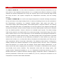
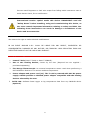
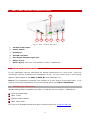
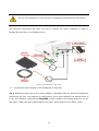
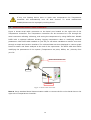
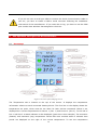
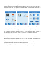
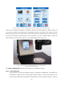
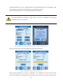
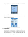
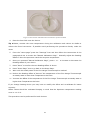
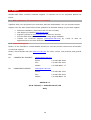
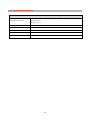
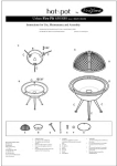
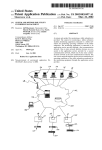
H401-T-DUAL-BL and H401-T-SINGLE-BL Temperature Controller User’s Manual Vers. 04.14 1 This page was left blank 2 1 Revision table Revision Number Additions or changes 01 Edited 02 Edited with new user manual format 03 04 Date Editor Giulio Pasquariello “Chamber connections” paragraph Removal Review July 2014 Amelia Liccardo December 2014 Amelia Liccardo December 2014 3 Silvia Foppiano Amelia Liccardo Index Index 1 REVISION TABLE ........................................................................................................................................ 3 2 PREFACE ......................................................................................................................................................... 5 3 SYMBOLS DESCRIPTIONS ...................................................................................................................... 6 4 SAFETY NOTES............................................................................................................................................. 7 5 EQUIPMENT SUPPLIED ............................................................................................................................ 8 6 H401-T-DUAL AND H401-T-SINGLE-DESCRIPTION .................................................................. 9 7 CONNECTIONS AND SYSTEM SETUP ................................................................................................. 9 7.1 Thermal plate connections................................................................................................ 9 7.2 Serial Communication cable connection ........................................................................... 12 8 UNIT OPERATION THROUGH TOUCH SCREEN INTERFACE .................................................. 13 8.1 Homepage ................................................................................................................... 13 8.2 LED Colours Meaning .................................................................................................... 14 8.3 General Settings ........................................................................................................... 14 8.3.1 Device configuration .................................................................................................. 14 8.3.2 Set-point change ....................................................................................................... 15 8.3.3 Touch Screen Settings ................................................................................................ 16 8.3.4 Alarm Settings .......................................................................................................... 17 8.4 Temperature Settings .................................................................................................... 18 8.4.1 Output Temperature Ramp Rate .................................................................................. 19 8.4.2 T-Unit Calibration ...................................................................................................... 19 8.4.3 Self-Calibration ......................................................................................................... 20 8.4.4 Manual Calibration ..................................................................................................... 22 8.4.5 Self-Calibration Advanced Settings. ............................................................................. 23 8.5 Status Page .................................................................................................................. 24 8.6 Info Page ..................................................................................................................... 24 9 ERROR MESSAGE ...................................................................................................................................... 25 10 TEMPERATURE CONTROL MECHANISM WITH OFFSETS .................................................. 26 11 SUPPORT ................................................................................................................................................ 28 11.1 Web conference for assistance and training ...................................................................... 28 11.2 Technical Support. ........................................................................................................ 28 11.3 Technical Specifications ................................................................................................. 29 12 TROUBLESHOOTING.......................................................................................................................... 30 13 FIGURE TABLE...................................................................................................................................... 31 4 2 Preface The H401-T-DUAL-BL is a dual channel temperature controller allowing temperature set up and control of two separate heating devices. It is a compact and effective solution to reliably maintain the desired temperature for living cell cultures right on the microscope stage within the range 25-50°C. The system comprises the Temperature Controller, and two heating devices. The H401-T-SINGLE-BL is a touch screen digital temperature controller allowing temperature set up and control of a single heating device. A variety of heating devices can be connected to the Temperature Controllers, for example: heating plates -both glass and metal- for microscope stages, glass heating tables, metal heating pads or objective heaters. The Heating Plates –both glass and metal- are designed to fit into the opening of XY stages of upright and inverted microscopes. Several models of glass and metal heating plate inserts can be selected from the Okolab portfolio. Custom solutions are available upon request. The Glass Heating Table can be placed in the optical path of any stereomicroscope. It provides a large, flat, clear, warm surface where one or more specimens can be maintained at physiological temperature. It is also suitable for small animal surgery. The Metal Heating Pad is a temperature-controlled surface that can be positioned on any laboratory workbench or desk surface (e.g. table top, cabinet work surface, etc.) to keep Petri dishes, Chambered and Glass Slides, and Tubes at the right temperature before microscope observation. The Objective Band Heater is designed to reliably maintain the desired temperature of the objective body and lens. This is important when the objective is in contact with the sample, during water dipping observation, or the tissue culture dish when imaging with oil immersion. The system is controlled via an intuitive, user-friendly touch screen interface. This instrument works with low voltage power, and accepts 24 Vdc. Temperature stability is ± 0.1°C. Temperature measuring accuracy is ± 0.2°C. Okolab DATA LOG is optional software allowing logging temperature data or modification of selected parameters. DATA LOG can be installed on your PC; Serial port connection to the Temperature Controller allows data download. 5 3 Symbols descriptions The following symbols identify important information to note: CAUTION or WARNING: This symbol warns you about the risk of electrical shock. CAUTION or WARNING or IMPORTANT: This symbol warns you of circumstances or practices that can affect the instrument’s functionality and must refer to accompanying documents. Tip ► Supplies you with helpful suggestions. Note ► Supplies you with important information to successfully setup and use the instrument. 6 4 Safety Notes In order to achieve maximum performance and to ensure proper operation of your new equipment, please read carefully the following safety notes and the instructions. If you have any question, please contact Okolab. The equipment must only be used as intended and as described in this Manual. Equipment should only be operated by technically qualified personnel. Do not start up the equipment if some of its parts are damaged. This instrument is not intended for use in locations subject to flammable or explosive gases. Transport the equipment with care. Equipment and its internal parts can be damaged by dropping and by shock. Some equipment parts may reach temperatures above 40-50°C. Take care when touching it. This device is not designed for use under medical conditions. Avoid rapid changes in ambient temperature which may cause condensation, avoid direct air draft from air conditioner, exposure to direct sunlight and excessive heat accumulation. Do not close Air Intake. Do not disassemble any part of the system and in particular of the heating units. Do not disconnect cables while in operation. Do not use a volatile solvent such as paint thinner to clean the instrument. Deformation or discoloration will occur. Use a soft, dry cloth to remove stains from the instrument. Do not exceed voltage indicated in this manual and on the product label. Avoid excessive induction noise, static electricity and magnetic fields. Do not expose this instrument to rain or moisture. Prevent throttling and kinking of cables. Do not start up the equipment if the supply cable is damaged. Connect the equipment only to grounded mains power socket. Before starting, assemble the equipment while unplugged from an outlet. 7 Prevent metal fragments or lead wire scraps from falling inside instrument case to avoid electric shock, fire or malfunction. International caution symbol marks this device. IMPORTANT: read the “Safety Notes” before installing, using and commissioning this device, as the notes contain important information relating to safety and EMC. Not following these instructions can result in damage or breakdown of the device and its accessories. We reserve the right to make technical modifications. IN NO EVENT OKOLAB S.R.L. SHALL BE LIABLE FOR ANY DIRECT, INCIDENTAL OR CONSEQUENTIAL DAMAGES OF ANY NATURE, OR FINANCIAL LOSS RESULTING FROM ANY DEFECTIVE PRODUCT OR THE USE OF ANY PRODUCT. 5 Equipment supplied 1 Control T Unit (H401-T-DUAL or H401-T-SINGLE). 2 One or two heating devices, chosen by the User (Required but not supplied – purchased separately) 3 Fine Gauge Thermocouple. An external temperature sensor used when performing a Self Calibration Routine or to monitor ambient temperature. 4 Power adapter and power cord (x1). The T-unit is powered with 24V DC power supply. Okolab provides a shielded power adapter compatible with the heating devices selected by the user. 5 DATA LOG. Software Data Logger to log temperature data from any OKOLAB device (Optional). 8 6 H401-T-DUAL and H401-T-SINGLE-Description 1 2 3 4 5 6 7 Figure 1. H401-T-Dual-BL. Rear panel. 1 24 VDC Power Input. 2 Power switch. 3 Serial port. 4 Ground connector 5 Fine Gauge Thermocouple port. 6 Device 1 port. 7 Device 2 port. This port is not present in H401-T-SINGLE-BL. 7 Connections And System Setup If your application requires controlling the sample temperature for a few hours, under the microscope, without controlling the composition of CO 2, you can connect one or two heating plates or Glass Tables to the H401-T-DUAL-BL (see paragraph 7.1). Note ► This temperature controller can manage up to two devices at the same time; if you need to control the temperature of only one heating device use H401-T-SINGLE-BL. 7.1 Thermal plate connections Okolab heating plates compatible with H401-T-DUAL-BL and to the H401-T-SINGLE-BL: Glass and Metal Plate H401-T-PAD Objective Band Heaters H401-Glass-Table For a list of all available models and specs of each product see: www.oko-lab.com. 9 Do not turn the device on until you have completed and checked all connections. The following instructions will show you how to connect the H401-T-DUAL-BL or H401-TSINGLE-BL with two or one Okolab devices. H401-T-DUAL-BL Device2 Thermocouple 24 VDC Power Feeder Device1 Figure 2. Thermal plates connections. 8 Connect the power adapter to the Temperature Controller Tip ► Okolab provides the correct power adapter compatible with the devices configuration selected by the user. The majority of configurations use a power adapter with Rating Power of 60 W. The following configurations REQUIRE a power adapter with Rating Power of 120 W: two H401-T-PAD; two H401-Glass-Table or one H401-Glass-Table and one H401-T-PAD 10 Please use the power adapter provided by Okolab or a power adapter for the recommended wattage to prevent system instability, random reset, unexpected shutdown, or problems due to insufficient power. If you start with a single device and you add a second one at a later time please ask an Okolab representative for the correct power adapter compatible with the new configuration. In no event shall Okolab S.r.l. be liable for any direct, incidental or consequential damages of any nature, or financial loss resulting from using the incorrect power adapter. 9 If you have a single heating device, connect it to “Device 1” port. If you have two heating devices connect one to “Device 1” and the other to “Device 2”. There is no “Device 2” port on the rear panel of H401-T-SINGLE-BL. 10 Turn Temperature Controller on using the rocking switch located on the right side panel. The following message will appear on the Touch Screen of the Temperature Controller. Figure 3. Initialization screeshot. 11 The Homepage will appear after completion of initialization. The temperature indicator will be initially yellow. 11 If any one heating device were to reach max temperature the Temperature Controller will automatically turn off both devices. To avoid malfunctions disable/disconnect the improperly working device. 7.2 Serial Communication cable connection Figure 4 shows serial cable connection to the Serial port located on the right side of the Temperature Controller. The Temperature Controller can be connected to a PC through the serial connection allowing collecting, and saving the temperature by using DATA LOG. Okolab DATA LOG is optional software allowing logging temperature data or modifying selected parameters. With DATA LOG installed on your PC you can select variables to monitor over time through a simple and intuitive interface. The collected data can then displayed in various graph forms for easier and faster analysis at the end of the experiment. The DATA LOG also allows modifying the parameters of the system (Temperature set point, Offset, etc.) directly from your PC. Serial Communication Port To PC Serial Port Figure 4. Serial Cable connection. Note ► Use a standard Serial Communication cable to connect the PC to the Serial Port on the right side of Temperature Controller. 12 If you do not have a serial port COM to connect the Serial Communication cable to your PC, you have to install a USB to serial converter following the installation instructions of the manufacturer. If you want also to log, you have to use the COM port number that Windows has assigned to the drive. 8 8.1 Unit Operation Through Touch Screen Interface Homepage Figure 5 Overview of the homepage screen The Temperature tab is located on the top of the screen. It displays the temperature information relative to each connected heating device. The first line on the display shows the temperature set point, which must be the same for both devices connected. Below it are displayed the current temperatures for Device 1 (Dev 1) and Device 2 (Dev 2). To the left of Dev 1 and Dev 2 a status indicator is also displayed (green dot in this example). The minimum (bottom) and maximum (top) temperature values that were reached within a selected time period are displayed on the right of the current temperature. To see the temperature 13 measured by the Fine Gauge Thermocouple, click on the “Status” button -with magnifying glass - on the bottom of the Touch Screen. For H401-T-SINGLE-BL there are only the Device 1 variables. Tip ►The Touch Screen is pre-set with a set point Temperature of 37°C. Once turned on it will start operating to reach this set-point value. 8.2 LED Colours Meaning A GREEN indicator means that set-point value has been reached (within the tolerance you’ve set) and that the system is working properly. . A YELLOW indicator means that the system is working towards reaching set points. NO actions on your part are required. Please note the Yellow light will also appear every time you change the Temperature set point. An ORANGE indicator means that the current gas concentration is not correct and its value is out of the set tolerance (see section “ALARMS” in paragraph 8.3.4). While giving time to the system to recover from this out-of-range value, please double check if there may be reasons not depending on the unit for which it is not properly working. Verify if all cables are correctly connected. A RED indicator means that something may have been damaged inside the unit. If after few hours the Red light doesn’t turn to Green, turn off the system and then turn it on again. If the problem persists, please contact Okolab for assistance http://oko- lab.com/onlineSupport.page 8.3 General Settings 8.3.1 Device configuration The first time you turn the system on, it is very important to verify that you are using the correct configuration parameters for your device. shows the homepage of a temperature controller with one Heated Glass Plate and one Heated Table. If you have different heating devices, or if you want to disable one of the outputs, you could perform the following procedure: 14 Figure 6 a) how to enter settings page and b) settings page Access the Settings Page by pressing the settings icon on the homepage (button with ‘gear’). Next press ‘Configuration’. Figure 7 a) configuration page and b) device settings page On the configuration page select ‘Devices’. In the next screen you can set the device currently connected to “Device 1” and “Device 2”. The system will load the correct parameters for the selected device. For H401-T-SINGLE-BL Only Device 1 is present in the configuration. 8.3.2 Set-point change To change set-point, simply touch the Temperature Tab on the homepage 15 Figure 8. Set Point change. The setting/regulation page will appear. Modify the set point by clicking + and –. Once you have input the new set point temperature press “Set” to save or “Cancel” to undo. Figure 9. Set point setting. 8.3.3 Touch Screen Settings Touch Screen Settings are reached by following the two steps shown below (look at the touching finger) 16 Figure 10 a) how to enter settings page and b) settings page 8.3.3.1 Rotate The first time you turn the system on, it is important to set the screen orientation Figure 11. How to choose the touch screen orientation. The screen is set by default in its “portrait” orientation. If you press the rotate button, you can rotate the screen by 180°. A 180° screen rotation is recommended in case you want to wall mount the Temperature Controller. In this page you can also disable the screen saver feature: by default, if the display has not been touched for 20 minutes, a black page with only the Temperature Tab is shown. Now you can press the “Home” button to go back to main page. Tip ► If you want to wall mount the Temperature Controller; contact Okolab to receive further assistance. 8.3.4 Alarm Settings You can set an Alarm to be triggered in case the temperature of the heating device deviates from the set point by a specific number of degrees Celsius and for a specific amount of time. See Figure 13 to access the Alarm Settings. 17 Figure 12 a) how to reach alarm page and b) alarms settings Wait until the system has reached steady state. The example in Figure 13 shows a temperature set point of 37°C and a Temperature Deviation of 0.5°C for a duration of 10 minutes. This means that an alarm will be triggered if the temperature reaches a value equal or less than 36.5°C or equal or more than 37.5°C for a period equal or longer than 10 minutes. Note ► If you want the Alarm to be acoustical rather than just being displayed, then flag “Buzzer”. 8.4 Temperature Settings Temperature options are accessed by clicking the Settings icon (look at the touching finger) Figure 13 a) how to enter settings page and b) settings page 18 8.4.1 Output Temperature Ramp Rate In some applications (i.e. in heating microscope objective body and lens), users may want to change the heating rate. The Temperature Controller allows you to modify the heating rate of each device independently (see Figure 14). Figure 14 a) how to configuration page, b) how to enter ramp rate page and c) ramp rate settings In the “Ramp Rate” page of the configuration screen, you can modify the heating rate of each device. In the example shown in Figure 14c we have a thermal plate connected as Device 1 and an objective heater band connected as Device 2. In this configuration Device 1 was set at the max heating rate, while Device 2 is set to be heated at a rate of 0.5°C per minute. For H401-T-SINGLE-BL there is only Device1 Ramp rate. 8.4.2 T-Unit Calibration The Temperature Controller is factory calibrated at a room temperature of 23°C. If your laboratory room temperature differs by more than 1°C from 23°C please consider performing an on-site Calibration Procedure for better accuracy. The procedure can be performed both on Device 1 and on Device 2, but only on one device at time since it requires the use of the Fine Gauge Thermocouple. The following pages show the procedure in detail for Device 1, with a T-Glass Plate connected. It can be performed with all other compatible devices following the same steps. 19 Figure 15 a) how to enter calibration page from settings page and b) calibration page There are two different calibration modalities, Manual and Self-Calibration. Select which one you want to perform by pressing the corresponding button (see Figure 15b) Place the Fine Gauge Thermocouple into a Petri dish. Fill the Petri dish with enough water to ensure that the tip of the Fine Gauge Thermocouple is fully immersed (3-4 ml of distilled water). Close the Petri dish with its lid and then place it on the Heating Plate (see Figure 16). Figure 16 Example of a petri dish with Fine Gauge Thermocouple placed onto a Thermal Plate. For H401-T-SINGLE-BL there are only the Device 1 calibration options. 8.4.3 Self-Calibration This procedure ensures the highest accuracy on specimen temperature. It monitors the temperature measured by the Fine Gauge Thermocouple in a Petri dish placed on the device under calibration and adjusts the temperature of the heating module in order to 20 keep the specimen at 37°C. This procedure is fully automatic and, once complete; it will permanently store the correction factor for the heating module. Press the ‘Start’ button to run the Self Calibration procedure. The Self-Calibration procedure it may take 1-2 hours to complete, the average calibration time is 90 minutes. Figure 17 How to start self-calibration procedure: click on start and then ok. Figure 18 shows the progress displayed during Self-Calibration Figure 18 Examples of Self calibration procedure. Wait until the dialog box in Figure 19 appears. It is possible to use the touch screen while the calibration is ongoing and reach pages other than the one above (Figure 18). 21 Once the calibration will be completed the screen in figure 19 will automatically reappear regardless of the screen you will be in. Figure 19 Example of a successful self-calibration procedure. Once the Self Calibration is completed you can remove the Fine Gauge Thermocouple from the Petri dish and start your experiment. Note ► On the Self Calibration page you can also reset the offset to the factory value of 0.00 °C, by pressing the Reset button. Figure 20 How to reset the offset stored after a calibration procedure 8.4.4 Manual Calibration This procedure is alternative to the previous one and operates by adding a fixed offset to the temperature of the plate so that the sample temperature -measured by the Fine Gauge thermocouple- will reach the set point. The Temperature Controller will adjust the power output to keep the temperature of the Plate at the desired value (taking offset into account). Wait for the Fine Gauge Thermocouple to reach a stable value. Next press + or – to input the difference in temperature between the plate and the reading from the Fine Gauge thermocouple (in this example 0.2°C), then press “Save”. 22 Figure 21 Example of a manual calibration procedure: the thermal plate sensor reads 37.0 °C, while the Fine Gauge Thermocouple measures 36.8 °C. Only one offset can be stored at any one time. Hence, a Manual Calibration will overwrite the result of any previous calibration including a Self Calibration one. 8.4.5 Self-Calibration Advanced Settings. The Self-Calibration Procedure continuously adjusts the temperature of the heating module until the specimen reaches at 37°C. Press Advanced Settings (see Figure 20). Figure 22 shows how you can increase or decrease the accuracy of the calibration procedure from a minimum of 0.15 to a maximum of 0.3 °C. A lower value will extend the duration of the calibration procedure but it will result in higher accuracy. This procedure is fully automatic and, once complete; it will permanently store the correction factor for the heating module. 23 Figure 22 Advanced Self Calibration settings 8.5 Status Page Press the ‘magnifying glass’ button to access the Status Page. On this page you can see the Status of the Temperature Controller and check that the system is working properly. The first two rows duplicate the information from the homepage in the Temperature Tab. The lower part of the screen displays the Fine Gauge Thermocouple (Free Sensor) reading. The additional parameters are displayed mainly for technical/control reasons. In case you requested support from one of Okolab engineers you may be asked for some of these data. Figure 23 Example of the status page when Fine Gauge thermocouple is disconnected. In H401-T-SINGLE-BL there is only the Device 1 column. 8.6 Info Page Press the button with the Okolab logo to access the Info Page. This page shows all the information related to the T-Unit version. Please have this information handy when contacting Okolab for support. 24 Figure 24 Info page, showing also the total system up-time. 9 Error Message If the system graphics fails to load, the system reverts to a non-graphic display and shows the following screenshot: Figure 25. Safe mode page. If this occurs, press the ‘restart in normal mode’ button so you can restart the device in normal mode. If this persists, please contact Okolab for support. When the system identifies a communication or electronic problem, it may display the following screenshot. 25 Figure 26. Communication Error page. This error may be due to a communication problem between Touch Screen and Temperature Controller. Contact Okolab for support http://www.oko-lab.com/onlineSupport.page Note ► Please note that this screen will always appear in the same orientation. If your Temperature Controller is wall mounted it will appear upside down. 10 Temperature Control Mechanism With Offsets The temperature of the heating device can be adjusted by manually changing offsets as follows: 1 Input temperature set point e.g. 37.0 °C 2 Insert the Fine Gauge Thermocouple (Free Sensor) into a Reference Sample (e.g. a 35mm dish). If needed, secure the external sensor to the bottom of the dish with tape. Add liquid (media or water) to the dish. Ensure that the tip of the sensor is fully immersed in liquid. Place the Reference Sample so prepared on the heating device and turn the Temperature Controller on. 3 Wait until steady state is reached. By measuring the specimen temperature with an external sensor, the offset values can be adjusted as described below. 26 Figure 27.Free Sensor attached on the internal base of the Petri Dish. 4 Place the Petri Dish onto the device. Tip ►Please, monitor the room temperature during the calibration and reduce air drafts to reduce the forced convection. If possible avoid performing this procedure directly under AC vents. 5 From the “Home page” press the “Settings” Icon and then follow the instructions of the paragraph 8.4.4 to access the “Manual Calibration Page”. Manually adjust the Reading Offset to have the specimen reach the set point temperature. 6 Once you accessed “Manual Calibration Page”, press + or - to increase or decrease the Reading Offset of your device. 7 Press “Save” to confirm the new Reading Offset of device. 8 Press “Home Page” icon to go back to the Home Page. 9 Wait until the steady state of the Fine Gauge Thermocouple is reached. 10 Reduce the Reading Offset of device if the temperature of the Fine Gauge Thermocouple at steady state is lower than Temperature Set Point. 11 Increase the Offset if the temperature of the Fine Gauge Thermocouple at steady state is higher than Temperature Set Point. If you change heating device you may have to modify the offset and re-calibrate for better accuracy. Offset values should be evaluated keeping in mind that the Specimen temperature reading error is ± 0.2 °C. This procedure can be performed for both devices. 27 11 Support Okolab staff offers excellent customer support. To contact one of our engineers please see below. 11.1 Web conference for assistance and training Together with your equipment you received a web cam and headset. You can request remote support over the web. Please follow these guidelines to facilitate setting up your web support: Webcam installation (instruction and Cd rom included) Last Skype ® installed (www.skype.com) Register yourself on www.skype.com to have an account Set the audio and video and test them using Skype software. Contact our technical support ([email protected]) by e-mail to take an appointment for the web assistance. 11.2 Technical Support. Please, do not hesitate to contact Okolab should you need any further commercial information or technical support. Please, check Okolab web site www.oko-lab.com for news, events, new products and general FAQ. For For COMMERCIAL SUPPORT: HARDWARE SUPPORT: [email protected] Phone +39 081 806 2624 Fax: +39 081 876 4410 Mobile: +39 348 96807 17 [email protected] Phone +39 081 806 3470 Fax: +39 081 876 4410 Mobile: +39 348 96807 18 Okolab S.r.l. Via A. Olivetti, 1 - 80078 Pozzuoli, NA Italy 28 11.3 Technical Specifications H401 T DUAL-BL and H401-T-SINGLE-BL – Technical Specifications Range: 25-50°C Temperature Device1/2 Step size: 0.1°C Accuracy: 0.2% Operating Temperature 0°C ~.+55°C Storage Temperature -5°C ~ +60°C Operating Humidity 0-70% Power Consumption 120 W max Weight 1 Kg 29 12 Troubleshooting Incorrect operations are often mistaken for malfunction. If you think that there is something wrong with a component, see the troubleshooting scheme below. If the problem persists even after troubleshooting as described below, please contact Okolab for support. Symptom Device off Device cold Probable cause Input-Output wrong connections Properly connect the cables to the input and to the output Input-Output cables damaged Substitute the cables Low set point value Change the set point Cable disconnected Connect the cable Cable damaged Replace the cable Actual temperature far from the Set Alarm rings Point temperature Cable disconnected Properly set the system. Connect the cable ERR_1. Temperature Sensor damaged ERR_2. Cable disconnected No temperature displayed ERR_# Remedy ERR_3. Fine Gauge Thermocouple not connected. ERR_4.Error on thermocouple measure Contact Okolab to receive assistance Properly connect the cable Connect the Fine Gauge Thermocouple Check the Thermocouple position Contact Okolab to receive assistance ERR_5. Board Error Contact Okolab to receive assistance ERR_6. Temperature read by Thermal plate sensor too high or too low Contact Okolab to receive assistance ERR_7. Generic Error Contact Okolab to receive assistance I check the previous troubleshooting but I cannot Contact Okolab to receive assistance solve the problem 30 13 Figure Table Figure 1. H401-T-Dual-BL. Rear panel. ............................................................................................ 9 Figure 2. Thermal plates connections. ........................................................................................... 10 Figure 3. Initialization screeshot. .................................................................................................. 11 Figure 4. Serial Cable connection. ....................................................... Error! Bookmark not defined. Figure 5 Overview of the homepage screen .................................................................................... 13 Figure 6 a) how to enter settings page and b) settings page ............................................................ 15 Figure 7 a) configuration page and b) device settings page .............................................................. 15 Figure 8. Set Point change. .......................................................................................................... 16 Figure 9. Set point setting. .......................................................................................................... 16 Figure 10 a) how to enter settings page and b) settings page ........................................................... 17 Figure 11. How to choose the touch screen orientation. ................................................................... 17 Figure 12 a) how to reach alarm page and b) alarms settings ........................................................... 18 Figure 13 a) how to enter settings page and b) settings page ........................................................... 18 Figure 14 a) how to configuration page, b) how to enter ramp rate page and c) ramp rate settings ...... 19 Figure 15 a) how to enter calibration page from settings page and b) calibration page ........................ 20 Figure 16 Example of a petri dish with Fine Gauge Thermocouple placed onto a Thermal Plate. ............ 20 Figure 17 How to start self-calibration procedure: click on start and then ok. ..................................... 21 Figure 18 Examples of Self calibration procedure. ........................................................................... 21 Figure 19 Example of a successful self-calibration procedure. ........................................................... 22 Figure 20 How to reset the offset stored after a calibration procedure ............................................... 22 Figure 21 Example of a manual calibration procedure: the thermal plate sensor reads 37.0 °C, while the Fine Gauge Thermocouple measures 36.8 °C. ................................................................................ 23 Figure 22 Advanced Self Calibration settings .................................................................................. 24 Figure 23 Example of the status page when Fine Gauge thermocouple is disconnected. ....................... 24 Figure 24 Info page, showing also the total system up-time. ............................................................ 25 Figure 25. Safe mode page. ......................................................................................................... 25 Figure 26. Communication Error page. .......................................................................................... 26 Figure 27.Free Sensor attached on the internal base of the Petri Dish. .............................................. 27 31 WARRANTY Okolab S.r.l. warrants the “H401-T-DUAL” to be free of defects in materials and workmanship for a period of two (2) years starting from invoice date. If the unit malfunctions, it must be returned to the factory for evaluation. If the equipment has to be returned to the factory, please ensure that is carefully and properly packed. Okolab S.r.l. accepts no responsibility for damage due to unsatisfactory packing. Upon examination of Okolab S.r.l., if the unit is found to be defective, it will be repaired or replaced at no charge. This warranty does not apply to defects resulting from any actions of the purchaser. Components which wear are not warranted. Okolab S.r.l. neither assumes responsibility for any omissions or errors nor assumes liability for any damages that result from the use of its products in accordance with information provided by Okolab S.r.l. . Okolab S.r.l. warrants only the parts manufactured by it will as specified and free of defects. Okolab S.r.l. makes no other warranties or representations of any kind whatsoever, express or implied, except that of title, and all implied warranties including any warranty of merchantability and fitness for a particular purpose are hereby disclaimed. LIMITATION OF LIABILITY: the total liability of Okolab S.r.l. shall not exceed the purchase price of the component upon which liability is based. In NO event shall Okolab S.r.l. be liable for consequential, incidental or special damages. 32