1
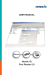
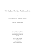
SOFTWARE GUIDE
PM1703MO SERIES
DATA PROCESSING SOFTWARE
Software for the Instrument
of PM1703MO Series
TABLE OF CONTENTS
PART I – Basic features ..................................................................................................... 3
Chapter 1 Overview and Installation
3
System requirements ......................................................................................................... 3
Installation........................................................................................................................... 5
Chapter 2 Quick Start
5
Step 1................................................................................................................................... 6
Initiating the IR link ............................................................................................................ 6
Initiating the Bluetooth link ............................................................................................... 6
Step 2 – Starting the program ........................................................................................... 9
Step 3 - Menus .................................................................................................................. 10
Step 4 – Program settings ............................................................................................... 11
Step 5 – Reading the history ........................................................................................... 14
PART II – Menu Commands ............................................................................................. 18
Chapter 3 Menu – File
18
“Save as” menu ................................................................................................................ 18
“Print” menu ..................................................................................................................... 18
“Exit” menu....................................................................................................................... 18
19
Chapter 4 Menu – Instrument
“Read history” menu........................................................................................................ 19
“Instrument settings” menu ............................................................................................ 19
“Switch off” menu ............................................................................................................ 23
“Clear DE” menu .............................................................................................................. 23
“Delete instrument” menu ............................................................................................... 24
24
Chapter 5 Menu – Tools
“Filter” menu..................................................................................................................... 24
“Add/change comment” menu ........................................................................................ 25
“Program setting" menu .................................................................................................. 26
“Instruments/History list” menu ..................................................................................... 27
Chapter 6 Menu – History
28
“Table view” menu ........................................................................................................... 28
“Graph view” menu .......................................................................................................... 28
“DER graph” menu........................................................................................................... 31
“DE graph” menu ............................................................................................................. 32
[email protected]
www.polimaster.us
2
_____________________________________________________________________________________
© 2012
Polimaster and its licensors. All rights reserved
PART I – BASIC FEATURES
Chapter 1 Overview and Installation
Polimaster and our support team are committed to provide high-quality technical support to the
users of our equipment and systems. This manual is indented to familiarize user with the
fundamentals of the Polimaster PM1703MO Series Data Processing Software (further –
Software) 1.
Software is installed on the personal computer (further – PC) and intended for use with the
Polimaster-manufactured instruments of the PM1703MO-XX 2 series (further – instrument).
The manual includes a summary of the basic features, a detailed overview of advanced features,
and the installation notes.
System requirements
•
•
•
•
IBM PC – compatible PC, Pentium III processor or higher;
1 GВ free HDD space;
CD-ROM drive (for installation);
Compatible operating systems:
• Microsoft Windows Vista;
• Microsoft Windows XP Professional;
• Microsoft Windows 2000 Professional;
• Saved files are compatible with Microsoft® Office® Excel (recommended)
• Database file is compatible with Microsoft® Office® Access (recommended)
for instruments with IrDA interface 3:
• Standard infrared (IR) adapter (USB or built-in);
for instruments with Bluetooth-interface3:
• Bluetooth adapter (USB or built-in) equipped with any driver:
o Microsoft Windows XP (SP2 or higher), Windows Vista, Windows 2000
o Widcomm or Broadcomm (4.х.х.х version or higher),
o IVT Corporation (BlueSoleil) (5.1.х.х version or higher).
For Instruments with USB-interface3:
• USB cable.
Documented Software and its settings are subject to change with no substantial effect on its functionality. Polimaster
reserves the right to change Software in such a way not mentioning it in Software Guides.
2
XX denotes alphanumeric code of an instrument within the РМ1703МО series. Look for the code in the instrument’s
user manual. The code informs of the way the instrument communicates with Software.
3
Instrument-supported interface type is given in its user manual.
1
[email protected]
www.polimaster.us
3
_____________________________________________________________________________________
© 2012
Polimaster and its licensors. All rights reserved
Attention!
•
Users have to examine the manuals on РМ1703МО-XX 1 to clear up the
instrument-supported interface type (IrDA, Bluetooth, and USB cable) themselves.
•
Adapters (IR, Bluetooth) are to be connected and set according to their in-line
documentation.
Note!
• Bluetooth adapter MUST support Bluetooth serial port (SPP) protocol;
• You can check Bluetooth driver version in Device Manager>Bluetooth Device
Properties>Driver folder of your PC
• Bluetooth driver version must be same or higher as listed above. If not, please
download the most current driver version from manufacturer’s website:
If not, please download the most recent driver version from manufacturer’s website:
o Microsoft (Windows XP SP2,Windows Vista) –
http://support.microsoft.com/kb/841803/en-us
o Widcomm\Boardcomm – http://broadcom.com/products/Bluetooth
o IVT Corporation (BlueSoleil) – http://bluesoleil.com/
XX denotes alphanumeric code of an instrument within the РМ1703МО series. Look for the code in the instrument’s
user manual. The code informs of the way the instrument communicates with Software.
1
[email protected]
www.polimaster.us
4
_____________________________________________________________________________________
© 2012
Polimaster and its licensors. All rights reserved
Installation
• Insert the installation CD in the computer’s CD drive and follow on-the-screen commands. If the
setup does not start automatically, click on Start, Run, and browse the CD drive for the
Setup.exe file. Click Open;
• Click Next in the InstallShield window when prompted;
• Read and accept the END USER LICENSE AGREEMENT;
• Select the destination folder: the default location is recommended;
(Default destination is ...\\Program Files\Polimaster\PM1703MO Series Data Processing
Software\);
• Check the installation settings and change if necessary by pressing Back. If settings are
correct, press Install;
• Press Finish after installation is complete.
Chapter 2 Quick Start
The Software should be used by qualified and properly trained personnel
only.
This chapter gives a brief description of the Software that allows the user to download, analyze
and manage the information from the РМ1703МО-XX 1 instruments.
Important Notes:
1. PM1703MO Series Data Processing Software is for use with the Polimaster
РМ1703МО-XX instruments only. Any attempt to communicate with other
device types using this software may have unpredictable results.
2. Software communicates with the instrument by:
Wireless communicating device:
• Standard infrared (IR) adapters compatible with the IrDA®
standard (with USB interface or built-in);
• Bluetooth adapter (with USB interface or built-in).
USB interface:
• The instrument is connected to PC by USB-cable.
Hardware and software installation of IR adapters or Bluetooth adapters is
XX denotes alphanumeric code of an instrument within the РМ1703МО series. Look for the code in the instrument’s
user manual. The code informs of the way the instrument communicates with Software.
1
[email protected]
www.polimaster.us
5
_____________________________________________________________________________________
© 2012
Polimaster and its licensors. All rights reserved
not the subject of this Software guide. If you experience problems with the IR
or Bluetooth adapters, please refer to the adapter’s user manual or contact
the seller/manufacturer.
Step 1
Initiating the IR link
IrDA communication between the РМ1703МО-XX (instrument) and the PC can be initiated in two
ways:
1) By installing the battery and immediately aiming the LCD screen of the instrument at IrDA
dongle. You will see “IR” displayed on the instrument’s LCD screen as the communications
are initiated (Fig. 1) as well as the IrDA icon appears in the Windows system tray (Fig. 2).
2) Pressing the Light button momentarily while in front of the IrDA dongle will initiate
communications if the instrument is powered on.
Fig. 1
Fig. 2
Initiating the Bluetooth link
Bluetooth communication between the РМ1703МО-XX (instrument) and the PC can be initiated
only when Bluetooth module of the instrument is switched on.
To do it sequentially press the MODE button on the instrument several times until the “-oFF-”
message appears on the LCD. Press the LIGHT button to switch the Bluetooth communication on.
(Fig. 3).
[email protected]
www.polimaster.us
6
_____________________________________________________________________________________
© 2012
Polimaster and its licensors. All rights reserved
Fig. 3
You will see “PC” (Fig. 4) displayed on the instrument’s LCD screen as the Bluetooth
communications are initiated as well as the Bluetooth icon changes its color in the Windows
system tray (Fig. 5).
Fig. 4
Fig. 5
[email protected]
www.polimaster.us
7
_____________________________________________________________________________________
© 2012
Polimaster and its licensors. All rights reserved
If Secured connection option is enabled on any instrument, the Bluetooth device will ask for PINcode or Passkey (Fig. 6) while connection setup attempt with РМ1703МО-XX.
Fig. 6
The authentication process, i.e. PIN-Code exchange is a property of the Secure connection
function. The default password is “5555”. If PIN-code exchange is successful during the initial
connection, “coupled pair” or “coupled connection” will be created. Further connection inside
"coupled pair" doesn't require authentication process.
To switch off the Secure connection function of Bluetooth device, right-click on the Bluetooth
icon on the Windows system tray. Press My Device Properties in the context menu. Go to
Services and switch off the Secure connection function in application properties window by
unflagging the Bluetooth serial port check-box (Fig. 7)
Fig. 7
[email protected]
www.polimaster.us
8
_____________________________________________________________________________________
© 2012
Polimaster and its licensors. All rights reserved
If the system still asks for PIN-code after switching off the Secure connection function of
Bluetooth device, the inquiry source can be in the РМ1703МО-XX instrument. This is a built-in
security feature and cannot be disabled. If so, enter PIN-code of РМ1703МО-XX. Default PINcode of the instrument is “5555”.
Step 2 – Starting the program
Click Start> Programs> Polimaster> PM1703MO Series Data Processing Software>
PM1703MO Series Data Processing Software to run software.
On the first run, you will go to the main window (Fig. 8).
Fig. 8
The PM1703MO Series Data Processing Software program supports 4 menus - File,
Instrument, Tools, and History. The following sections describe the functions and commands of
each menu. A toolbar, below the menu bar, contains buttons that correspond to frequently used
menu commands. When the cursor is placed on a toolbar button, the corresponding command
name will be displayed alongside as a hint.
A Status Bar, in the bottom line displays some current program settings (Filter On/Off etc.), Graph
mode and other information.
The History menu submenus and corresponding toolbar buttons will be active after first data
download only.
[email protected]
www.polimaster.us
9
_____________________________________________________________________________________
© 2012
Polimaster and its licensors. All rights reserved
Step 3 - Menus
File Menu
This menu contains the commands to save and print files and allows the user to exit the program.
Fig. 9
Instrument Menu
This menu contains a set of commands to operate the instrument such as reading the history,
changing internal instruments settings, etc.
Fig. 10
Tools Menu
This menu contains set of the commands to control the event table window screen of PM1703MO
Series Data Processing Software, such as apply different event filters, and toggle between
instruments and events lists, and changing the program settings (changing the password to
access database, setting up the connection to the instrument, selecting the measurement units).
Fig. 11
[email protected]
www.polimaster.us
10
_____________________________________________________________________________________
© 2012
Polimaster and its licensors. All rights reserved
History Menu
This menu contains a set of commands to control the data representation window. It allows the
user to toggle between table and graph data representation and between DER and DE graphs.
Fig. 12
Step 4 – Program settings
Before using Software several settings must be configured.
To set the program before using, click either the Program Settings command in the Tools menu
or the Program Settings button on the toolbar
.
Fig. 13
Program Settings:
IrDA — select (
) this radio button if communication with instrument will be under IrDA protocol.
[email protected]
www.polimaster.us
11
_____________________________________________________________________________________
© 2012
Polimaster and its licensors. All rights reserved
Bluetooth drivers — select (
under Bluetooth protocol.
) needed radio button if communication with instrument will be
Select appropriate Bluetooth driver supporting Bluetooth adapter that is installed in your
system.
You can define producer name or version number of Bluetooth driver:
- referring to in-line documentation for Bluetooth adapter
or
- referring to installed Bluetooth adapter properties. Right-click on My Computer then go to
Properties >Device >Device Manager. Select Bluetooth category. Select Properties by rightclicking. (Fig. 14)
Fig. 14
Note!
Bluetooth driver version should be the same or higher as specified in
Program settings windows:
o Microsoft Windows XP (SP2 or higher),
o Windcomm or Broadcomm (4.х.х.х or higher),
o BlueSoleil (5.1.х.х or higher).
If not, please download the most recent driver version from manufacturer’s website:
o Microsoft (Windows XP SP2,Windows Vista) – http://support.microsoft.com/kb/841803/en-us
o Widcomm\Boardcomm – http://broadcom.com/products/Bluetooth
o IVT Corporation (BlueSoleil) – http://bluesoleil.com/
If you still fail to set Bluetooth adapter, contact your system administrator.
Measurement units — select appropriate radio button (
) to change measurement units.
[email protected]
www.polimaster.us
12
_____________________________________________________________________________________
© 2012
Polimaster and its licensors. All rights reserved
Change password - default password is “1”. Password is case sensitive. To change password,
first enter old password, then enter and confirm new password.
To save new settings, click Ok button.
[email protected]
www.polimaster.us
13
_____________________________________________________________________________________
© 2012
Polimaster and its licensors. All rights reserved
Step 5 – Reading the history
To read the history from the instrument, click either the Read history command in the Instrument
menu or the Read history button on the toolbar (Fig. 15).
Fig. 15
Software will search for the instruments that are available for IR or Bluetooth communications
(Fig. 16).
Fig. 16
The checkbox on the bottom left of the screen, allows the user to switch the instrument off
automatically after all history events are downloaded.
After the desired instrument is found, data will automatically be downloaded from instrument and
saved to the local database (Fig. 17).
Fig. 17
[email protected]
www.polimaster.us
14
_____________________________________________________________________________________
© 2012
Polimaster and its licensors. All rights reserved
The main program window (Instruments list) will be populated with the instrument’s name
together with serial number, registration date (when the instrument was written into the database
in format dd/mm/yy and comments (Fig. 18).
Fig. 18
If the annual operability evaluation period of this particular instrument is expired, you will see the
window shown in Fig. 20.
Fig. 19
Users can set a new evaluation date themselves. This function becomes available only when the
current evaluation date is expired.
By clicking Yes button (Fig. 19) the user will open standard Windows calendar to set the next
instrument evaluation date (Fig. 20).
[email protected]
www.polimaster.us
15
_____________________________________________________________________________________
© 2012
Polimaster and its licensors. All rights reserved
Fig. 20
Instrument’s history reading resumes upon selection of the evaluation date.
To view the history data of a particular instrument, double click on the appropriate row in the
instruments list. The History list window will appear (Fig. 21).
Fig. 21
[email protected]
www.polimaster.us
16
_____________________________________________________________________________________
© 2012
Polimaster and its licensors. All rights reserved
To switch back to the Instruments list click either the Instruments/History list command of the
Tools menu or the appropriate toggle button on the toolbar (Fig. 22). Please, refer to Chapter 5
for more details.
Fig. 22
Double-clicking on the columns name of the Instruments list sorts the list by the clicked column
(instrument’s name or registration date or added comments).
Double-clicking on the columns name of the History list sorts the list by date and time
simultaneously (Fig. 23).
Fig. 23
[email protected]
www.polimaster.us
17
_____________________________________________________________________________________
© 2012
Polimaster and its licensors. All rights reserved
PART II – MENU COMMANDS
Description of each menu command is shown along with the corresponding toolbar icon.
Chapter 3 Menu – File
This menu contains file processing commands.
“Save as” menu
Writes the data in the active window to the file. Either instruments list or history list can be saved
to file with a user specified filename and path. All saved files are Microsoft® Excel compatible.
Fig. 24
“Print” menu
Sends the active window’s data (instruments list, history list or plot) to the designated printer.
Fig. 25
“Exit” menu
Exits the program and returns to Windows.
Fig. 26
[email protected]
www.polimaster.us
18
_____________________________________________________________________________________
© 2012
Polimaster and its licensors. All rights reserved
Chapter 4 Menu – Instrument
The Instrument menu provides commands, allowing access to the instrument’s internal
parameters and history data.
“Read history” menu
As described in Chapter 2, the Read history menu provides user with access to the events
history stored in the internal non-volatile memory of the instrument. Stored events include
periodical background data as well as alarms, thresholds exceed, calibration events, switching
instrument on and off, and changing the alarm signal events. All events are accompanied with
corresponding timestamps.
“Instrument settings” menu
The instruments settings menu allows the user access to the instrument’s internal parameters,
such as threshold values, alarm settings, etc.
Fig. 27
Important note!
User is not recommended to change the factory preset settings. It may
cause incorrect readings and faulty operation.
To access parameters you will be prompted to specify the password (Fig.28). Default password is
"1".
Fig. 28
If the typed password is correct, the instrument’s settings will be read and the Instrument
settings window will appear (Fig. 29). This window has 3 tabs – Instrument, Thresholds and
General.
[email protected]
www.polimaster.us
19
_____________________________________________________________________________________
© 2012
Polimaster and its licensors. All rights reserved
Fig. 29
The Instrument tab displays information about instrument’s name, serial number, date/time as
recorded in the internal memory and set instrument operability evaluation date. These settings are
read-only. New evaluation date can be set only upon expiration of the previous evaluation date.
Please, refer to Chapter 2 Step 5 for more details.
The Thresholds tab allows the user to read and change thresholds (Fig. 30). Numbers in
brackets indicate allowable settings ranges that correspond to measurement ranges.
Attention!
Alarm levels in the Search Mode are derived from the ambient background. When
the instrument runs through background calibration, it acquires a background
reading and calculates the alarm levels automatically based on the value of n
coefficient set by the user.
The value of n coefficient may be set in the range of 1.0 to 9.9 through every 0.1.
The smaller the n coefficient value is, the more sensitive the instrument is to
[email protected]
www.polimaster.us
20
_____________________________________________________________________________________
© 2012
Polimaster and its licensors. All rights reserved
background radiation changes. Besides this behavior also increases the false
alarms rate (false positives). Increasing the value of n coefficient decreases the
sensitivity of the unit to minor changes in radiation background. It starts responding
to considerable radiation field variations (intensive radiation sources nearby) only
and probability of false alarms decreases.
The manufacturer’s recommended value is 5.3.
To save changed threshold values to the instrument press the Write button on the bottom line. To
close the window without saving changes press the Close button. To re-read settings press the
Read button.
Fig. 30 a
Fig. 30 b
The General tab in the Instrument settings window (Fig. 31) can be used to get and set the
general parameters of the instrument, including alarm enabling, changing of the readings
displaying mode, etc.
[email protected]
www.polimaster.us
21
_____________________________________________________________________________________
© 2012
Polimaster and its licensors. All rights reserved
Fig. 31
General Settings:
History recording interval – gets and sets the time interval (in minutes) for background data
logging to the internal nonvolatile memory;
Allow clearing DE – when this box is checked, the user can clear the accumulated DE from the
instrument’s memory by means of the instrument’s buttons;
Allow setting alarms – when this box is checked, the user can switch the audio and vibration
alarms on and off by means of the instrument’s buttons;
Allow changing thresholds - when this box is checked, the user can change the threshold value
by means of the instrument’s buttons;
Sound enable – this checkbox enables the sound alarm;
Vibro enable – this checkbox enables the vibration alarm;
Button beep enable – when this box is checked button strokes are accompanied by a sound
tone;
Display prefix “0”’s – this box allows the user to display insignificant preceding zeroes before the
numerical value of the character display, i.e. 0005 uR/h versus 5 uR/h;
Display readings fine - when this box is checked, the display resolution is two digits after the
decimal point, when unchecked – one digit after the decimal point;
Enable visual alarm - when this box is checked, the display backlight automatically turns on while
instrument alarming and red alarm LED is enabled.
[email protected]
www.polimaster.us
22
_____________________________________________________________________________________
© 2012
Polimaster and its licensors. All rights reserved
Mode 0…9 - when this box is checked, the mode 0…9 is turned on. In this mode user can set the
threshold and the device indicates the cases of its excess.
After turning on this mode and pressing the MODE button, in addition to the DER and DE
measurement modes the instrument should display the screen of the 0…9 mode (with the number
“0” in the absence of a dose rate threshold exceeding). In the case of exceeding on the screen will
be displayed the degree of the excess on the scale from 0 to 9.
If the 0…9 mode is turned on, the line Searching threshold from the tab Thresholds is active,
and it is possible to change the searching threshold (Fig. 30 b). If the 0…9 mode is disabled,
instrument calculates the alarm levels based on the value of n coefficient set by the user (Fig. 30
a).
Note!
If after activation of the 0...9 mode the instrument doesn’t display the window
of this mode, it means that the instrument belongs to earlier versions and
does not support this mode.
“Switch off” menu
Allows the user to switch off the instrument (Fig. 32). The user will be prompted to enter the
password to perform this operation.
Fig. 32
“Clear DE” menu
Allows the user to null the accumulated ambient dose equivalent (DE) in the instrument’s memory
(Fig. 33).
Fig. 33
[email protected]
www.polimaster.us
23
_____________________________________________________________________________________
© 2012
Polimaster and its licensors. All rights reserved
Note!
This operation cannot be undone; all the information about accumulated DE
will be lost permanently. You will be prompted to confirm this operation.
“Delete instrument” menu
Active in Instruments list mode only and for selected row only.
Allows user to delete the selected instrument’s history records from the local database (Fig. 34).
Attention!
This operation cannot be undone; all history records from the selected
instrument will be lost. You will be prompted to confirm this operation.
Fig. 34
Chapter 5 Menu – Tools
The Tools menu provides commands that allow the user to change the data representation on the
program screen.
“Filter” menu
The Filter menu (Fig. 35) allows the user to specify which records in the database will be
displayed in the History list window.
Fig. 35
[email protected]
www.polimaster.us
24
_____________________________________________________________________________________
© 2012
Polimaster and its licensors. All rights reserved
To apply the filter, select the Filter command from the Tools menu or press the appropriate
button on the toolbar. Filter window will appear (Fig. 36).
Fig. 36
The top section of the Filter window can be used to specify the type of events to be displayed on
screen. The bottom section can be used to specify the time period. Both the event and data range
filters can be used simultaneously. The Status line in left bottom corner of the main window shows
the current status of the filter – ON or OFF (Fig. 37). The Data range filter is also active in the
Graph view mode while the Event filter is only active in the History table view mode (refer to
Chapter 6 for more details about view modes).
Fig. 37
“Add/change comment” menu
The Add/change comment menu (only active in the Instruments list view mode (refer to
Instruments/History list menu in the current chapter for more details about view modes)) is used
for adding or editing comments to selected instrument in the list (Fig. 38, Fig. 39).
[email protected]
www.polimaster.us
25
_____________________________________________________________________________________
© 2012
Polimaster and its licensors. All rights reserved
Fig. 38
Fig. 39
Any text information may be added as a comment to a particular instrument, such as the user’s
name, etc. Comments are displayed on the Instruments list alongside the instrument’s model,
serial number and instrument’s registration date (Fig. 40)
Fig. 40
“Program setting" menu
The Program settings menu allows the user to set the communication protocol (Bluetooth or
IrDA), to select the driver supporting the installed Bluetooth adapter, as well as to set the
measurement units 1 and to change access password. Please, refer to Chapter 2 Step 4 for more
details.
1
To synchronize instrument’s measurement units with software-displayed units.
[email protected]
www.polimaster.us
26
_____________________________________________________________________________________
© 2012
Polimaster and its licensors. All rights reserved
To change the password, select the Program settings command from the Tools menu or press
the appropriate button on the toolbar (Fig. 41).
Fig. 41
Press the Change password button in the Program settings window. You will be prompted to
type both the old and a new password (Fig. 42) and to confirm the new password.
Fig. 42
“Instruments/History list” menu
The Instruments/History list menu and appropriate toolbar toggle button (Fig. 43) are used for
switching between two main program windows – Instruments list and History list.
Fig. 43
Note!
This function is inactive if no instrument was selected
[email protected]
www.polimaster.us
27
_____________________________________________________________________________________
© 2012
Polimaster and its licensors. All rights reserved
Chapter 6 Menu – History
The History menu provides commands, allowing the user to change the history data
representation. The History representation menu has two basic modes – Table view and Graph
view. In the Table view mode all (or filtered, refer to Chapter 5, Filter menu) events are
represented in the table. In the Graph view mode the accumulated dose equivalent (in DE graph
mode) or background dose equivalent rate (in DER graph mode) history is represented as a
graph with the corresponding timestamp on the X-axis.
“Table view” menu
The Table view menu (Fig. 44) is used for switching the main History window from the History
graph mode to the default table view mode.
Fig. 44
“Graph view” menu
The Graph view menu (Fig. 45) is used for switching the main History window from the default
Table view mode (dataset) to the History graph mode.
Fig. 45
After switching to the Graph view mode, the History graph window will appear (Fig. 46). The
software provides a number of tools to simplify data study and analysis, as described below.
[email protected]
www.polimaster.us
28
_____________________________________________________________________________________
© 2012
Polimaster and its licensors. All rights reserved
Fig. 46
The plot in this window graphically represents the changing background DER and is automatically
scaled.
To select the area of interest (to move the entire plot), right click the mouse then drag the graph.
Release the mouse button to complete the operation.
You may want to take a closer look at interesting areas of your data, particularly if you have a
large number of points. To enlarge the area of interest, left click the mouse, then drag the area
of interest with the cursor from the top left corner of the area of interest to the bottom right corner
(Fig. 47). Release the mouse button to complete the operation. The area of interest will be
magnified and the axes will be rescaled automatically.
[email protected]
www.polimaster.us
29
_____________________________________________________________________________________
© 2012
Polimaster and its licensors. All rights reserved
Fig. 47
To return the axes to their original scale, left click then drag any plot window location and move
the cursor from bottom right to the top left corner. After releasing the mouse button axes will be
returned to their original scale.
To read the data at a particular point, double-click on the desired plot point or on the
corresponding X-axis date and time. The Red cursor line will be moved to the selected point; the X
and Y marker values will be displayed in the status line (Fig. 48).
Attention!
The cursor can only be moved to a point but not between the points; the line
does not represent the real background change between two points in the
dataset.
[email protected]
www.polimaster.us
30
_____________________________________________________________________________________
© 2012
Polimaster and its licensors. All rights reserved
Fig. 48
To select a particular span of dates, apply the appropriate Date range filter (refer to Chapter 5
for more information).
All the highlighted operations are valid for both DE and DER plots.
“DER graph” menu
The DER graph menu (Fig.49) is used to switch the History graph window to the dose equivalent
rate (DER) plot mode. This control is only active in the Graph view and not in the Table view.
Fig. 49
[email protected]
www.polimaster.us
31
_____________________________________________________________________________________
© 2012
Polimaster and its licensors. All rights reserved
“DE graph” menu
The DE graph menu (Fig. 50) is used to switch the History graph window to the dose equivalent
(DE) plot mode. This control is only active in the Graph view, not in the Table view.
Fig. 50
Thank you for choosing Polimaster!
[email protected]
www.polimaster.us
32
_____________________________________________________________________________________
© 2012
Polimaster and its licensors. All rights reserved