1
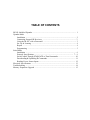
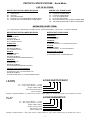
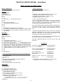
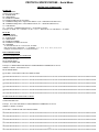
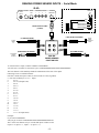
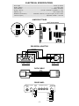
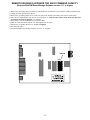
USER MANUAL
“The Home of Automation”
12200 Thatcher Court Poway, CA 92064-6876
TEL 858-486-8787
FAX 858-486-8789
EMAIL [email protected]
TABLE OF CONTENTS
IR-XP2 InfraRed Xpander .................................................................................................. 1
Xpander Mode
Installation ................................................................................................................. 2
Connecting External IR Receivers ........................................................................... 3
Using the IR-XP2 with a Powermid .......................................................................... 3
Set Up & Learning ..................................................................................................... 4
Repeat ....................................................................................................................... 4
Programming ............................................................................................................. 5
Serial Mode
Installation ................................................................................................................. 6
Protocol Specifications ........................................................................................ 7 - 9
Serial Control Through STARGATE or TimeCommander ....................................... 10
Downloading & Uploading IR Commands ................................................................ 11
Reading Power Sensor Inputs .................................................................................. 12
Electrical Specifications ................................................................................................... 13
Troubleshooting ................................................................................................................. 14
Memory Expansion Upgrade ............................................................................................ 15
IR-XP2 INFRARED XPANDER
The IR-XP2 Infrared Xpander is a multi-function 2-way learning infrared controller that can store, send and receive up to 250 IR
commands (expandable to 500 with memory upgrade) from existing remote controls. It has 2 user-selectable modes of operation:
1) Xpander Mode - for use as an add-on to TimeCommander, TimeCommander-Plus or STARGATE via the aux port.
2) Serial Mode - for direct control by computer (ASCII) via RS232 serial port.
(Internal jumpers are provided to select mode of operation.)
(FRONT VIEW)
IR WINDOW
IR INPUT JACK
TRANSMIT LED
INDICATOR
RECEIVE LED
INDICATOR
(REAR VIEW)
POWER INPUT
FUTURE EXPANSION PORT
(NOT USED)
RS232 / AUX
SERIAL PORT
EMITTER OUTPUTS
POWER SENSOR
INPUTS
Xpander Mode
In Xpander Mode, the IR-XP2 can issue any combination of IR commands in response to any input condition(s) in the Event Manager
schedule such as time, X-10, analog or digital input, ascii, etc. For example: if the time is 7:30pm Monday-Friday and the security system
is armed (no one is home) then turn on the vcr, select channel 7 and record Jeopardy for 30 minutes.
Serial Mode
In Serial Mode, the IR-XP2 can be operated directly from any computer or device capable of sending/receiving ascii commands via RS232.
This provides an open platform for incorporating custom software and adding IR control to any system that supports ascii. Serial protocol
specifications are included in the Serial Mode section of this manual. All IR control functions can be accessed using Windows Terminal
program or other programs that can send/receive ascii commands via the serial port.
TM
PC
TIMECOMMANDER,
TIMECOMMANDER-PLUS
OR STARGATE
COMPUTER
2
IR-XP
IR-XP2
EMITTERS
Xpander Mode
Serial Mode
-1-
EMITTERS
INSTALLATION (Xpander Mode)
1) Check that firmware version 2.28 or higher is installed in your TimeCommander (or TimeCommander-Plus) by clicking
SYSTEM INFO in Event Manager for Windows (firmware version is listed on top line). If not, obtain & install a firmware upgrade.
2) Connect one end of the provided data cable to the RS232/AUX jack on the rear panel of the IR-XP 2.
3) Connect the other end of the data cable to the AUX jack on the STARGATE, TimeCommander or TimeCommander-Plus.
USE THE PROVIDED DATA CABLE ONLY! THIS IS A DATA TYPE CABLE NOT A STANDARD PHONE CORD.
4) Plug the power adaptor into the POWER IN jack.
5) Plug the provided IR-emitter into EMITTER OUTPUT jack #1.
6) Remove the adhesive tape from the IR emitter and place the exposed sticky side over the IR window of your tv (or other device
to be controlled).
TO STARGATE,
TIMECOMMANDER
OR TIMECOMMANDER-PLUS
"AUX" JACK
POWER IN RS-485
12VDC
500mA
RS232
AUX
EMITTER OUTPUTS
1
2
3
4
POWER
SENSORS
IR EMITTER
DATA CABLE
7) For control of multiple IR devices (tv, vcr, stereo, etc.), connect additional IR emitters to Emitter Outputs 2 - 4.
(For control of more than four IR devices, use Dual Emitters).
TO STARGATE,
TIMECOMMANDER
OR TIMECOMMANDER-PLUS
"AUX" JACK
POWER IN RS-485
12VDC
500mA
RS232
AUX
EMITTER OUTPUTS
1
2
3
4
POWER
SENSORS
IR EMITTERS
DATA CABLE
DUAL IR EMITTER
9) If the IR emitters need to be placed far from the IR-XP2, extension cables can be added to increase the distance up to 1000 feet.
Recommended wire type: Catagory 5 twisted pair.
10) Emitter Outputs can also be connected to other IR distribution systems for added capacity and flexibility.
POWER IN RS-485
12VDC
500mA
RS232
AUX
EMITTER OUTPUTS
1
2
3
4
POWER
SENSORS
PWR
-2-
EMITTERS
+12VDC
GND
STATUS
SIGNAL
AMPLIFIED EMITTER CONNECTING BLOCK
(Xantech #791-44)
CONNECTING EXTERNAL IR RECEIVERS TO THE FRONT PANEL INPUT
The 3.5mm jack on the front panel of the IR-XP2 is an opto-isolated direct infrared input that can be connected to the emitter
output of another system. This allows the use of external infrared receivers to send infrared signals to the IR-XP2.
CONNECTING
BLOCK
12
12
PWR
IR
RECEIVER
EMITTERS
+12VDC
GND
GND
SIGNAL
XMIT
REC
IR
RCVR
3.5mm plugs
IR
RECEIVER
IR
RECEIVER
USING THE IR-XP2 WITH A POWERMID
POWER
12VDC
RS485
RS232/
AUX
EMITTER OUTPUTS
1
2
3
4
POWER
SENSORS
Mini-Emitter
When using the IR-XP2 with a Powermid, place the stick-on mini-emitter directly over the IR sensor of the Powermid transmitter
(see diagram for placement).
-3-
SET UP & LEARNING - Xpander Mode
(for use with Stargate, Stargate-Lite, TimeCommander or TimeCommander-Plus)
SET UP
1) Open WinEVM (Event Manager for Windows).
2) Click DEFINE then click IR AND IO DEVICES then click IR-Xpander
with the left mouse button to access the IR SETUP menu.
3) Click the first blank line of the NAME list.
4) Type the name of the IR command you wish to learn (eg: TV POWER)
then use the down arrow key (or click with the left mouse button) to
advance to the next line.†
5) Repeat step 4 for each IR command you wish to learn.
Be sure that no two IR commands share the same name. Use numbers
to differentiate similar IR commands (TV1 POWER, TV2 POWER, etc.).
6) To change an IR command name, click the appropriate name in the list,
type the new name, then click on another line or press the down arrow key.
7) Be sure to have all your hand-held remote controls handy with fresh
batteries installed.
LEARNING
1) After all IR commands are named, click SELECT ALL to highlight all defined
names or individually click each IR command in the list that you wish to learn. ††
To individually highlight multiple IR commands, click on the number to the left
of each name in the list you wish to include, or hold down the SHIFT key while
clicking on each name.
2) Click LEARN to begin the Learning IR process.
3) At the "PRESS BUTTON NOW" prompt, aim your hand-held remote control
at the front panel IR Window of the IR-XP2 (about 3 - 4 feet away) and briefly
press
the corresponding button. The IR-XP2 "XMIT" led will light briefly to indicate
the command has been learned then the "PRESS BUTTON NOW" prompt will
automatically advance to the next selected IR command in the list.
Press Button Now !
0
4) If "LEARN TIMEOUT" appears:
click TRY AGAIN then press the corresponding IR button again, or
click SKIP to advance to the next IR command and continue, or
click CANCEL to escape.
5) To change or re-learn an IR command, click the appropriate name in the list,
then click LEARN and follow the prompt as in step 7.
6) To test an IR command, double-click the appropriate name in the list or highlight the name (single-click) then click PLAY.
7) If you are using multiple emitter outputs (zones), you can assign each emitter output a different name for easy identification when
programming schedules. Simply click on each emitter output box, then type the name (eg: Home Theater, Family Room, etc.).
8) The default LEARN TIMEOUT of 10 seconds should give adequate time to aim your hand-held remote at the IR-XP2 and press the
appropriate button when prompted. If more time is required, click the UP ARROW button in the IR SETUP LEARN TIMEOUT
box to select a longer timeout.
REPEAT
When REPEAT is selected in the IR SETUP menu, any IR commands (40KHz range) received at the front panel IR window, learned or
not, will be routed to the selected emitter output(s). This allows control of IR devices in other rooms from one central location. To use the
REPEAT function, click the appropriate box for the emitter output(s) you wish the repeated IR signals to be directed to. If the IR-XP2 is
located in the same room as the IR-controlled devices, use the included BLACK (IR OPAQUE) SHELL and IR WINDOW MASK to
prevent interference from reflected IR signals (see instructions included with IR emitter).
NOTES
†
When typing in the names of each IR command, try to follow the order in which they appear on your remote controls. This will simplify
the learning process by allowing you to listen for the "PRESS BUTTON NOW" voice prompt as a cue when to press the next remote control
button rather than watching the screen. If you wait too long after the "PRESS BUTTON NOW" voice prompt, the "TIMEOUT" voice prompt
will sound and the learning process will pause until you take the appropriate action (Try Again, Skip or Cancel).
††
The default carrier frequency for the IR-XP2 is 40.0 kHz which should work for most systems. However, before learning all IR commands
for each remote control, it is recommended that you first try learning and playing one IR command to confirm that the default frequency
functions properly (remote controls from different manufacturers may operate at different carrier frequencies). If the IR command still does
not play or is intermittent, follow the troubleshooting procedures in the "Troubleshooting" section before trying different a carrier frequency.
The last 16 memory locations (lines #235-250 and #485-500) accommodate ir commands with large data streams. If a learned command
doesn't play, try learning it into one of the last 16 lines instead.
-4 -
PROGRAMMING - Xpander Mode
(for use with Stargate, Stargate-Lite, TimeCommander or TimeCommander-Plus)
THEN IR
1) After all IR commands are learned, open your existing schedule (or create a new one).
2) To program an event to play IR commands, click the THEN line of the event, click ADD, then click IR to access the
IR COMMANDS menu.
Play
3) Select the IR command name, the emitter output(s) to send it to, and the number of times to play the IR command,
then click OK. The IR command will appear in the THEN section of the event.
4) Repeat step 3 for each IR command you wish to add to the schedule. Example:
EVENT: Home Theater Power On
If
(XSEQ: A-1 A-ON) is Received Within 3 seconds
Then
(IR:VCR POWER) send (1) times [Home Theater]
(IR:TV POWER) send (1) times [Home Theater]
(IR:TV CHAN 3) send (1) times [Home Theater]
(IR:AMP POWER) send (1) times [Home Theater]
End
5) Download the schedule.
IF IR
1) To program an event to respond to an IR command (40KHz range), click the IF line of the event, click ADD, then click IR to
access the IR CONDITION menu.
2) Select the desired IR command to respond to, then click OK. The IR command will appear in the IF section of the event.
NOTE: “IF IR” IS COMPATIBLE WITH IR COMMANDS 1 THROUGH 250 ONLY.
3) Complete the “THEN” section of the event. Example:
EVENT: TV Power Triggers Lights
If
(IR:TV POWER) is received
Then
(X:Family Rm Lts A-1) Set Level 50%
End
4) Download the schedule.
-5-
INSTALLATION - Serial Mode
1) Remove any static charge from your hands by touching the bare metal chassis of your computer or other grounded surface.
2) Remove the two Phillips head screws on the rear panel of the IR-XP2 and carefully slide out the circuit board.
3) Locate the four jumpers just behind the RS232 jack on the edge of the circuit board.
4) Move jumpers J1 and J2 to the RS232 position (see diagram).
IR-XP2 CIRCUIT BOARD
RS-485
J3
J4
RS232
AUX
J2
J1
SERIAL MODE
5) Slide the circuit board back into the enclosure.
6) Replace the rear panel.
7) Connect one end of the provided data cable to the RS232/AUX jack on the rear panel of the IR-XP 2.
8) Connect the other end of the data cable into the provided DB-9 Serial Adaptor.
USE THE PROVIDED DATA CABLE ONLY! THIS IS A DATA TYPE CABLE NOT A STANDARD PHONE CORD.
9) Plug the DB-9 Serial Adaptor into your computer serial port (com port).
10) Plug the power adaptor into the POWER IN jack.
11) Plug the provided IR-emitter into EMITTER OUTPUT jack #1.
12) Remove the adhesive tape from the IR emitter and place the exposed sticky side over the IR window of your tv (or other device
to be controlled).
POWER IN RS-485
12VDC
500mA
RS232
AUX
EMITTER OUTPUTS
1
2
3
4
POWER
SENSORS
DB-9 Serial Adaptor
IR
EMITTER
DATA CABLE
TO COMPUTER
SERIAL PORT
-6-
PROTOCOL SPECIFICATIONS - Serial Mode
LIST OF OP CODES
WRITES THAT ARE FOLLOWED BY READS
C0 RESET
C1 ID REQUEST
D0 READ IO
D2 READ REGISTERS
F8 MASTER UPLOAD FROM IRXP2 LOWER MEM
FA MASTER UPLOAD FROM IRXP2 UPPER MEM
WRITES THAT STAND ALONE
D9 WRITE REGISTERS
F4 LEARN IR LOWER MEM
F6 LEARN IR UPPER MEM
F5 PLAY IR LOWER MEM
F7 PLAY IR UPPER MEM
F9 MASTER DOWNLOAD TO IRXP2 LOWER MEM
FB MASTER DOWNLOAD TO IRXP2 UPPER MEM
MESSAGES (SHORT FORM)
CC = CHECKSUM. CHECKSUM VALIDITY IS NOT USED, HOWEVER A VALUE (00 or CC) MUST APPEAR.
WRITES THAT ARE FOLLOWED BY READS
WRITES THAT STAND ALONE
RESET
WRITE TO IRXP2:
6C82C0CC6D
READ FROM IRXP2:
6CC0AAIRXP-10000CC
ID REQUEST
WRITE TO IRXP2:
6C82C1CC6D
READ FROM IRXP2:
6CC1AAIRXP-10000CC
READ IO
WRITE TO IRXP2:
6C82D0CC6D
READ FROM IRXP2:
6CD0XD00WOM1M2000000NMNDFSCC
READ REG
WRITE TO IRXP2:
6C82D2CC6D
READ FROM IRXP2:
6CD2STRPMDMTDSDBCFRA000000CC
MASTER UPLOAD FROM IRXP2
WRITE TO IRXP2:
6C84F8FSNSCC6D or 6C84FAFSNSCC6D
READ FROM IRXP2:
6C84F8FSNSDD..DDCC or 6C84FAFSNSDD..DDCC
WRITE REG
WRITE TO IRXP2:
6C84D9RRDDCC
LEARN IR
WRITE TO IRXP2:
6C86F4SATOCFSRCC or 6C86F6SATOCFSRCC
PLAY IR
WRITE TO IRXP2:
6C85F5SANRAPCC or 6C85F7SANRAPCC
DOWNLOAD TO IRXP2
WRITE TO IRXP2:
6C8FF9NSDD..DD or 6C8FFBNSDD..DD
LEARN
6C86F4SATOCF00CC
F4 = Learn Lower Memory (1-250)
F6 = Learn Upper Memory (251-500)
Sample Address (HEX)
Time Out [Seconds] (HEX)
Carrier Frequency
Example: 6C86F401100000CC = Learn to lower memory, sample address #1, timeout 16 seconds, carrier frequency 40.0 kHz.
PLAY
6C85F5SANPAPCC
F5 = Play Lower Memory (1-250)
F7 = Play Upper Memory (251-500)
Sample Address (HEX)
Number of Plays (HEX)
Alternate Play / DSP
Emitter Output Port
Example: 6C85F5010303CC = Play lower memory, sample address #1, play 3 times, alternate play off, emitter ports 1 and 2.
-7-
PROTOCOL SPECIFICATIONS - Serial Mode
WRITES THAT ARE FOLLOWED BY READS
RESET, ID REQUEST
SHORT FORM IS SELF EXPLANATORY.
READ IO
WRITE TO IRXP2:
6C82D0CC6D
READ FROM IRXP2:
BYTE:
01 6C
02 D0
03 4321XXXX 4..1 ARE DIGITAL INPUTS
04 00
05 00
06 MOST RECENT MATCH
07 SECOND MOST RECENT MATCH
08 00
09 00
10 00
11 NUMBER OF MATCHES NOT SUCCESSFUL
12 ND NUMBER OF SAMPLES LAST SUCCESSFULLY DOWNLOADED
13 FS NUMBER OF "FALSE STARTS" FOR MATCH FUNCTION
14 CHECKSUM
READ REG
WRITE TO IRXP2:
6C82D2CC6D
READ FROM IRXP2:
BYTE
01 6C
02 D2
03 STATUS BYTE (see below) *
04 XXXXRRRR RRRR = REPEAT PORTS 4..1
05 MATCH DELTA ACCURACY
(0-0x0f, DEFAULT=0x04)
06 MATCH TOTAL DIFFERENCE ACCURACY (0-0x7f, DEFAULT=0x7f)
07 XDSPXXXX DSP=REPEAT DSP VARIANCE (SEE WRITE REG)
08 DEBUG BYTE (see WRITE REGISTER section for bit meanings)
09 CARRIER FREQUENCY EQUATION RESULT FOR REPEATS (00 = 40K)
10 CARRIER FREQUENCY TO SAMPLE RATIO (00 = 1)
11 00
12 00
13 00
14 CHECKSUM
* STATUS BYTE BITS (INDICATE "SINCE LAST TIME READ")
7 LEARN_SUCCESSFUL
6 LEARN TIME OUT
5 232 TIME OUT
4 N/A
3 CONTROLLER DOWNLOAD TO IRXP2 TIMEOUT
2 MICROPROCESSOR RESET
1 MATCH OCCURED
0 BAD COMMAND RECEIVED BY IRXP2
WRITE REG
WRITE TO IRXP2:
6C84D9RRDDCC
AVAILABLE REGISTERS (RR):
01 XXXXRRRR R=REPEAT PORT
02 MATCH DELTA ACCURACY
(0-0x0f, DEFAULT=0x04)
03 MATCH TOTAL DIFFERENCE ACCURACY
(0-0x7f, DEFAULT=0x7f)
04 XDSPXXXX DSP=REPEAT DSP VARIANCE:
DSP=PLAY DSP VARIANCE:
0 = NORMAL 1=-3, 2=-3, 3=-1, 4=+1, 5=+2, 6=+3
EXAMPLE: 6C 84 D9 04 30 cc OR 6C 84 D9 04 40
05 DEBUG **
-8-
** DEBUG BYTE BITS
7 LOAD DEFAULTS ON STARTUP ***
6
5
4
3 FEEDBACK LED IN REPEAT MODE ON/OFF (1=ON)
2 VERBOSE MATCH DEBUG ON/OFF (1=ON)
1 JDS DEBUG (MATCH ONLY) ON/OFF (1=ON)
0 NORMAL DEBUG ON/OFF (1=ON)
*** BIT 7 OF THE DEBUG BYTE:
A ONE IN THIS BIT POSITION WILL CAUSE ALL PARAMETERS TO IMMEDIATELY BE RESET TO THEIR DEFAULT
STATE AND WILL CAUSE DEFAULT PARAMETERS TO BE
LOADED UPON SUBSEQUENT START-UPS.
ANY CHANGES MADE TO PARAMETERS WILL TAKE EFFECT
BUT WILL NOT BE SAVED TO NON-VOLATILE MEMORY
AND WILL NOT BE LOADED UPON SUBSEQUENT STARTUPS.
A ZERO IN THIS BIT POSITION WILL CAUSE ALL PARAMETERS TO IMMEDIATELY BE SAVED TO NON-VOLATILE
MEMORY AND WILL CAUSE SAVED PARAMETERS TO BE
LOADED UPON SUBSEQUENT START-UPS.
ANY SUBSEQUENT CHANGES MADE TO PARAMETERS WILL
BE SAVED TO NON-VOLATILE MEMORY.
THIS BIT COMES FROM THE FACTORY SET IN THE ONE
POSITION.
EXAMPLES
LEARN 1ST ADDRESS (00)
PLAY 1ST ADDRESS
6C86F400100000CC
6C85F500010FCC
LEARN 250TH ADDRESS (F9)
PLAY 250TH ADDRESS
6C86F4F9100000CC
6C85F5F9010FCC
FULL DEBUG ON
MATCH (JDS DEBUG) ON
DEBUG OFF
6C84D90501CC
6C84D90502CC
6C84D90500CC
REPEAT ON (ALL 4 OUTPUTS) 6C84D9010FCC
REPEAT OFF
6C84D90100CC
ID (FIRMWARE VERSION REQUEST) 6C82C1CC6D
(Response = 6CC1 A A I R X P 2 E0000FF)
PROTOCOL SPECIFICATIONS - Serial Mode
WRITES THAT STAND ALONE
LEARN IR
WRITE TO IRXP2:
6C86F4/6SATOCFSRCC
F4: LOWER MEM
F6: UPPER MEM
SA: SAMPLE NUMBER
TO: LEARN TIMEOUT IN SECONDS
CF: CARRIER FREQUENCY EQUATION RESULT (00 = 40K WHICH IS DEFAULT)
SR: CARRIER FREQUENCY TO SAMPLE RATIO (00 = 1 WHICH IS DEFAULT)
CC: CHECKSUM
CF = 5,000,000 / CARRIER FREQUENCY (CONVERT TO HEX)
Example: 36.7KHZ: CF = 5,000,000 / 36,700 = 136.2 => ROUND TO 136 (DECIMAL) = 88 (HEX)
PLAY IR
WRITE TO IRXP2:
6C85F5/7SANPAPCC
F5: LOWER MEM
F7: UPPER MEM
SA: SAMPLE NUMBER
NP: NUMBER OF TIMES TO PLAY
AP: ADSPPPPP
A=ALTERNATE PLAY 1=ON/0=OFF, P=PORT
DSP=PLAY DSP VARIANCE: 0 = NORMAL 1=-3, 2=-3, 3=-1, 4=+1, 5=+2, 6=+3
Example: 6C85F501013FCC or 6C85F701014FCC
UPLOAD/DOWNLOAD
UPLOAD FROM IRXP2 TO COMPUTER
WRITE TO IRXP2:
6C84F8/FAFSNSCC6D
READ FROM IRXP2:
6C84F8/FAFSNSDD..DD
Example: TO READ FROM THE IRXP2 LOWER MEMORY ADDRESSES 02 TO 04:
WRITE TO IRXP2: 6C84F80203CC6D
READ FROM IRXP2:
DATA WILL UPLOAD IN THE FOLLOWING FORM:
--0200010203040506070809101112131415161718192021222324252627282930313233334353637383940414243444546474849505152535455566768696061626364
--0201010203040506070809101112131415161718192021222324252627282930313233334353637383940414243444546474849505152535455566768696061626364
--0300010203040506070809101112131415161718192021222324252627282930313233334353637383940414243444546474849505152535455566768696061626364
--0301010203040506070809101112131415161718192021222324252627282930313233334353637383940414243444546474849505152535455566768696061626364
--0400010203040506070809101112131415161718192021222324252627282930313233334353637383940414243444546474849505152535455566768696061626364
--0401010203040506070809101112131415161718192021222324252627282930313233334353637383940414243444546474849505152535455566768696061626364
DOWNLOAD FROM COMPUTER TO IRXP2
WRITE TO IRXP2:
6C8FF9/FBNSDD..DD
Example: TO LOAD THE IRXP2 LOWER MEMORY ADDRESSES 02 TO 04:
WRITE TO IRXP2: 6C8FF903
DATA WILL LOAD IN THE FOLLOWING FORM:
--0200010203040506070809101112131415161718192021222324252627282930313233334353637383940414243444546474849505152535455566768696061626364
--0201010203040506070809101112131415161718192021222324252627282930313233334353637383940414243444546474849505152535455566768696061626364
--0300010203040506070809101112131415161718192021222324252627282930313233334353637383940414243444546474849505152535455566768696061626364
--0301010203040506070809101112131415161718192021222324252627282930313233334353637383940414243444546474849505152535455566768696061626364
--0400010203040506070809101112131415161718192021222324252627282930313233334353637383940414243444546474849505152535455566768696061626364
---90401010203040506070809101112131415161718192021222324252627282930313233334353637383940414243444546474849505152535455566768696061626364
PROTOCOL SPECIFICATIONS - Serial Mode
SERIAL CONTROL OF IR-XP2 THROUGH STARGATE,
STARGATE-LITE, TIMECOMMANDER OR
TIMECOMMANDER-PLUS
To convert the standard serial protocol to Stargate/TimeCommander format:
1) Begin with ##%28
2) Add the 6C byte
3) Insert 0 followed by the number of two-character bytes that follow
(for a "learn" command insert 07, for a play command, insert 06)
4) Add the remainder of the ASCII string
5) Change the last checksum byte (CC) to 00
Examples:
COMMAND
LEARN 1ST ADDRESS (00)
PLAY 1ST ADDRESS
STANDARD
SERIAL
PROTOCOL
6C86F400100000CC
6C85F500010FCC
STARGATE/
TIMECOMMANDER
FORMAT
##%286C0786F40010000000
##%286C0685F500010F00
NOTE: When sending Stargate/TimeCommander format commands to a Stargate or TimeCommander, be sure
to send at the correct baud rate (9600 or 2400), No Parity, 8 Data Bits, 1 Stop Bit, Flow Control OFF (none).
- 10 -
DOWNLOADING AND UPLOADING IR COMMANDS - Serial Mode
Learned IR commands can be downloaded from the IR-XP2 to a computer for storage and later retrieval. A complete IR setup can then
be uploaded to an IR-XP2 rather than performing the learning procedure. This is useful when setting up multiple systems with similar IR
devices. Once uploaded, ir commands can be edited as described in the SET UP section.
UPLOAD IR commands to your pc:
F8 = Save Lower Memory
FA = Save Upper Memory
6C84F800FACC6D
Beginning Sample Address (HEX)
Number of Samples (HEX)
Example: 6C84F800FACC6D = Upload lower memory, begin with sample #00, 250 samples (#00-#249).
DOWNLOAD IR commands from your pc:
6C8FF9FA
Number of Samples
Example: 6C8FF9FA = Download 250 samples.
DATA UPLOAD TO THE PC FROM IRXP2
1.) SET THE WINDOWS TERMINAL MENU OPTIONS:
SETTINGS/ COMMUNICATION/ 2400 BD, 8-BITS, 1-STOP BIT, NO PARITY, NO FLOW CONTROL
TRANSFERS/ RECEIVE TEXT FILE/ FILE NAME: (EXAMPLE) C:\IRXPDATA.TXT
This should initiate a receive text file mode.
2.) WRITE TO IRXP2: 6C84F800FACC6D
00 is the starting sample number
250 (FA) is the number of samples desired to be downloaded
replace F8 with FA for upper bank memory locations 251-500
This should cause the file transfer. It will take a couple of minutes for all the data to be transfered.
- 11 -
READING POWER SENSOR INPUTS - Serial Mode
IR-XP2
POWER IN RS-485
12VDC
500mA
RS232
AUX
EMITTER OUTPUTS
1
2
3
POWER
SENSORS
POWER
SENSORS
4
GND
SENSOR INPUT 1
SENSOR INPUT 2
SENSOR INPUT 3
SENSOR INPUT 4
+5VDC
MODULAR DATA CABLE
(6-COND.)
(LIGHT DETECTOR PROBE)
(TV SNIFFER PROBE)
PLACE
NEAR
TV
(AC POWER PROBE)
(VIDEO DETECTOR PROBE)
PLUG INTO
VIDEO
OUTPUT
PSS-JBX
POWER SENSOR
JUNCTION BOX
To read all of the 4 inputs, send the command: 6C82D0006D
You will receive in return 14 consecutive bytes: 6CD0#XXXXXXXXXXXXXXXXXXXXXXX
The first character of the third byte holds the information on the state of the inputs.
Following is how to read that character.
Note that 1 means the input is OFF (5v) and 0 means it is ON (at ground).
# = first char of third byte 4 3 2 1 = inputs
#
4 3 2 1:
0
0 0 0 0 (all inputs ON)
1
0001
2
0010
3
0011
4
0100
5
0101
6
0110
7
0111
8
1000
9
1001
A
1010
B
1011
C
1100
D
1101
E
1110
F
1 1 1 1 (all inputs OFF)
Example:
If you send: 6C82D0006D
And you get in return: 6CD05X00XXXXXXXXXXXXXXXXXXXX
The 5 as the first character of byte 3 means that inputs 2 and 4 are ON
(input 4 = 0, input 3 = 1, input 2 = 0, input 1 = 1).
- 12 -
PLACE
OVER
INDICATOR
LIGHT
ELECTRICAL SPECIFICATIONS
Power Input .................................................................................................. 12VDC @ 500mA
Emitter Outputs ................................................................................................ (4) 3.5mm jacks
LED Indicators ...................................................................................... (2) XMIT, RECEIVE
Storage Capacity ................................................. 250 IR Commands (expandable to 500)
Memory Type ............................................................................................... Non-Volatile Flash
Baud Rate (Serial Mode) ................... 2400 baud, 8 data bits, 1 stop bit, no parity, no flow control
Carrier Frequency ..................................................................... Adjustable, Default = 40.0 kHz
JUMPER SETTINGS
IR-XP2 CIRCUIT BOARD
RS-485
J3
J4
RS-485
J3
J4
RS232
AUX
J2
J1
XPANDER
MODE
AUX
RS232
J2
J1
SERIAL
MODE
DB9 SERIAL ADAPTOR
YELLOW (TX)
GREEN (GND)
RED (RX)
BL
Y
GR
R
BK
W
FRONT VIEW
REAR VIEW
DATA CABLE
BLUE
YELLOW
GREEN (RX)
RED (GND)
BLACK (TX)
WHITE
REAR PANEL
POWER IN RS-485
12VDC
500mA
RS232
AUX
EMITTER OUTPUTS
1
Tx
GND
2
3
4
GND
PS-1
PS-2
PS-3
Rx
PS-4
+5VDC
- 13 -
POWER
SENSORS
TROUBLESHOOTING
TimeCommander or STARGATE cannot communicate with the IR-XP2
1) Check that both the Timecommander or STARGATE and IR-XP2 are powered up.
2) Check that jumpers J1 through J4 are all in the "AUX" position.
3) Check that the correct DATA CABLE is connected between the "RS232/AUX" jack of the IR-XP2 and the "AUX" jack of the
TimeCommander or STARGATE.
4) Check that the correct software (WinEVM 1.10 or higher) and firmware (version 2.28 or higher) are installed.
5) Check that "IR-XPANDER" is selected in the UTILITES | OPTIONS | IR REMOTE menu.
Computer cannot communicate with the IR-XP2 (Serial Mode)
1) Check that both the computer and IR-XP2 are powered up.
2) Check that jumpers J1 and J2 are in the "RS232" position and J3 and J4 are in the "AUX" position.
3) Check that the correct DATA CABLE is connected between the "RS232/AUX" jack of the IR-XP2 and the DB-9 Serial Adaptor.
4) Check that the correct DB-9 Serial Adaptor is connected.
Some IR commands work but others don't
NOTE: THE IRXP2 IS COMPATIBLE WITH REMOTES IN THE 20KHz - 85KHz RANGE
1) Check that you have fresh batteries in the remote you are having problems with.
2) Position the problem remote control at different distances and angles from the IR-XP2 IR window when learning.
3) Press the remote control button very briefly when learning.
4) Check that the IR-XP2 IR Window is not exposed to fluorescent lighting when learning IR commands.
5) Try learning the questionable ir command(s) into one of the last 16 memory locations (#235-250 or #485-500) .
6) Select ALT (Alternate Play) in the IR SETUP menu for the IR commands that don't operate, then re-download the schedule.
7) Select a different carrier frequency then try re-learning and playing the IR command. There are several popular carrier frequency
choices available: 40.0 kHz, 36.7 kHz, 56.8 kHz and 38.0 kHz, 20KHz, 85KHz.
8. Some cable box remotes use no carrier frequency. Select 20KHz for these remotes.
Repeat does not function or is intermittent
NOTE: REPEAT WILL ONLY FUNCTION WITH REMOTES THAT USE 40KHz CARRIER FREQUENCY
1) Try aiming your remote at a slight angle to the IR-XP2.
2) Turn off (or relocate) space heaters or other nearby sources of IR energy.
3) If the IR-XP2 is located in the same room as the IR-controlled devices, use the included BLACK (IR OPAQUE) SHELL and
IR WINDOW MASK to prevent interference from reflected IR signals (see instructions included with IR emitter).
4) Click REPEAT DSP to select a different DSP value and retry the Repeat. There are 7 choices for Repeat DSP (0, 1, 2, 3, 4, 5, 6).
The IR-XP2 is designed for compatibility with IR remote controls of varying models and manufacturers. However, due to differences
in IR formats used by different manufacturers, it is possible to experience difficulty learning or playing certain IR commands. If you
experience problems, first follow the troubleshooting procedures in this section. If you continue to experience difficulties, contact the
dealer/distributor from whom you purchased or contact JDS Customer Support at:
Attn: Customer Service
JDS Technologies
12200 Thatcher Court
Poway, CA 92064-6876 U.S.A.
TEL 858-486-8787 M-F 10am-4pm PT
FAX 858-486-8789
EMAIL [email protected]
- 14 -
MEMORY EXPANSION UPGRADE FOR 500 IR COMMAND CAPACITY
(Requires WinEVM Event Manager Software version 1.11 or higher)
1) Remove any static charge from your hands by touching the bare metal chassis of your computer or other grounded surface.
2) Unplug all cables from from the IR-XP2.
3) Remove the two Phillips head screws on the rear panel of the IR-XP2 and carefully slide out the circuit board.
4) Place the new Flash Memory Chip into the vacant socket (U2). Make sure the notch is facing the proper direction
and all pins are lined up properly (see diagram).
5) Press down to seat the Flash Memory Chip in the socket.
6) Slide the circuit board back into the case and align the rear face plate.
7) Replace the two phillips head screws - do not overtighten.
8) Reconnect all cables.
9) Install WinEVM Event Manager Software version 1.11 or higher.
NOTCH
--U2
----
- 15 -
-----