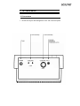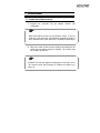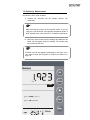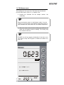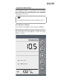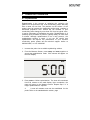
1
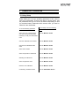
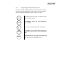
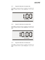
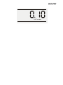
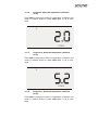
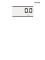
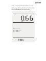
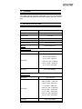
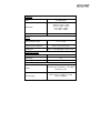
TABLE OF CONTENTS
1 INTRODUCTION
1
2 UNPACKING THE METER
2
3 GETTING STARTED
3
3.1
Connectors
3
4 USING THE METER
5
4.1
4.2
4.3
Conductivity Probes
Display/ Keys
Screen Display
5
7
8
5 CONDUCTIVITY OPERATION
9
5.1 Using Setup
5.1.1
Using setup from the measure screen
5.1.2
Program 1: View the calculated cell constant
5.1.3
Program 2: View the standardized value
5.1.4
Program 3: Select the conductivity mode
5.1.5
Program 4: Select resistivity mode
5.1.6
Program 5: Select the TDS mode
5.1.7
Program 6: Select the cell constant (1.00)
5.1.8
Program 7: Select the cell constant (10.00)
5.1.9
Program 8: Select the cell constant (0.10)
5.1.10 Program 9: Select the temperature coefficient
16
5.1.11 Program 10: Select the temperature coefficient
5.1.12 Program 11: Select the temperature coefficient
5.1.13 Program 12: Select the temperature coefficient
5.1.14 Program 13: Select the TDS Factor (0.40 Ð 1.00)
5.1.15 Program 14: Temperature unit selection (¡C)
5.1.16 Program 15: Temperature unit selection (¡F)
5.1.17 Program 16: Enable the STABLE icon
5.1.18 Program 17: Disable the STABLE icon
9
10
12
13
14
14
14
15
15
15
(2.0%)
(5.2%)
(0.0%)
(1.5%)
17
17
19
20
21
21
22
23
6 STANDARDIZATION
25
6.1
Using Setup
25
7 MEASUREMENT
28
7.1 Conductivity Measurement
7.2 Resistivity Measurement
7.3 TDS Measurement
7.4 Temperature Measurement
28
30
31
31
8 CONDUCTIVITY OPERATION
33
8.1
Replatinization
9 CONDUCTIVITY THEORY
34
10 CLEANING
38
11 METER SPECIFICATIONS
38
12 WARRANTY
40
33
13 NOTICE OF COMPLIANCE
41
14 REPLACEMENT PARTS
42
14.1 Replacement parts
42
1
INTRODUCTION
Thank you for selecting the Fisher Scientific Accumet AB 30
bench-top meter. This instruction manual describes the operation
of the meter. The state-of-art meter that you have purchased is
easy to operate and will guide you through the various functions
by displaying easy to understand prompts.
This instruction manual is designed to provide all the information
necessary to guide you through the process of measuring pH or
mV with a series of prompts on the screen.
F
You will find this symbol appearing in this manual; it indicates
useful tips that ease your meter operation.
The Accumet AB30 provides microprocessor precision in a
compact benchtop design that is easy to use. This meter allows
you to:
§
§
§
§
Measure conductivity, resistivity and Total Dissolved Solids
(TDS).
Select cell constants,
temperature coefficients,
and
temperature units.
Standardize with two key strikes
Replatinise your conductivity probe
It all adds up to rapid, completely automatic, intuitive operation.
2
UNPACKING THE METER
The following is a listing of what you should have received with
your Accumet AB 30 conductivity meter.
Meter with kit includes
Meter
Power supply
Electrode arm support bracket
Electrode arm
ATC probe
Manual and literature
Note that this meter does not include a conductivity cell
RS 232 communication cable
Meter only includes
Meter
Power supply
Electrode arm support bracket
Manual and literature
If any of these items are missing, please contact the Fisher
Products Group electrochemistry Division by dialling 412/490-6267
Accessory Conductivity Probes are available and can be ordered
by calling Fisher Customer Service at 800/766-7000.
2-cell Conductivity Probes:
Cell Constant
Optimal Conductivity Range
Glass Body
Epoxy Body
0.1
0.5 to 200 uS
13-620-156
13-620-161
1.0
0.01 to 2.0 mS/cm
13-620-155
13-620-160
10.0
1 to 200 mS/cm
13-620-157
13-620-162
4-cell Conductivity Probes:
Cell Constant
Optimal Conductivity Range
Glass Body
Epoxy Body
1.0
0.01 to 2.0 mS/cm
13-620-163
13-620-165
10.0
1 to 200 mS/cm
13-620-164
13-620-166
3
GETTING STARTED
3.1 Connectors
1. Review the layout and arrangement of the rear connector panel.
2. Connect the electrode arm to the base.
3. Connect the power cable to the connector cable to the rear
connector panel power jack and to a power source.
4
USING THE METER
4.1 Conductivity Probes
This meter allows you to use both 2-cell and 4-cell conductivity
probes.
F
DO NOT connect both probes together.
Remove the protective cover from the end of the probe. Prior to
use, soak the probe in distilled or deionized water for 10 minutes.
1. Install the 2-cell probe by plugging the pin connectors into the
dual pin jacks on the back of the meter.
OR
Install the 4-cell probe by plugging in its DIN connector into the
DIN jack on the back of the meter.
Install the ATC probe by plugging the 1/8Ó mini-phone jack into the
ATC jack on the back of the meter.
F
The Accumet 4-cell probe has built-in ATC and a separate ATC
probe is not required.
2. Rinse the conductivity probe
sensing elements with distilled or
deionized water between samples.
3.
For long term storage, the
probes can be stored dry or in distilled
water.
F
Note that the cell constant may change slightly due to storage or
use, and it must be re-evaluated with the use of standard
conductivity solution (standardization) prior to use.
4.2 Display/ Keys
Overview of the meter screen display and function key layout.
Press std key to initiate
standardization from measure
mode. Or press std key at the
Standardize mode to confirm
the standardization and
return to Measure mode.
Press setup key to access
setup for configuration of
meter setting.
Press _ key to increase value
or scroll up selection.
Press enter key to confirm
selection or change being
made.
Press stdby key to start up or
put the meter in standby
mode.
4.3 Screen Display
Familiarize yourself with the layout of the digital screen display.
5
CONDUCTIVITY OPERATION
5.1 Using Setup
Setup allows you to set the operating parameters of the meter to
meet your requirements. There are two ways to access setup, and
the parameters that you can set will be different depending on how
you accessed setup. Determine which access route you need to
utilize from the chart below:
To set the following parameter
Access Setup from the following
screen
Select the type of measurement
you wish to make (conductivity,
resistivity or TDS) and associated
units.
From the Measure Screen
View the calibrated cell constant
From the Measure Screen
View the last calibrated buffer
value
From the Measure Screen
Select Cell constant
From the Measure Screen
Select Temperature coefficients
From the Measure Screen
Selecting the TDS factor
From the Measure Screen
Select Temperature units
From the Measure Screen
Clear the user calibration
From the Measure Screen
Conductivity standard solution
From the Standardize Screen
5.1.1
Using setup from the measure screen
If you are currently viewing the Setup screen, setup is in essence
a scroll button which allows you to access, view, and change a
variety of operating parameters. While in setup, you may:
std
Press std to exit from setup to measure screen
without making change.
setup
Press setup to scroll to the next parameter to
view or change.
p
enter
stdby
Press π to set values within each setup option.
Press enter to accept the displayed parameter.
The meter will then return to the measurement
mode.
Press stdby to return to the stdby mode without
making a change. Pressing stdby again will
place the meter in the Measure mode.
Program 10:
Select Temperature
Coefficient (5.2%)
Program 1:
View Cell Constant
C ell Constant
- View the calculated cell constant
stored in memory. A series of
dashes Ò- - -Ó appears if there is
no cell constant in memory.
- Select the temperature
coefficient from 2.0%, 5.2%,
0.0% or 1.5%. Default is 2.0%.
COEFF
Program 2:
View standardized value
Program 11:
Select Temperature
Coefficient (0.0%)
- View the standardized value. A
series of dashes Ò- - -Ó appears if
the meter is not standardized.
- Select the temperature
coefficient from 2.0%, 5.2%,
0.0% or 1.5%. Default is 2.0%.
COEFF
µS
Program 12:
Select Temperature
Coefficient (1.5%)
Program 3:
Conductivity Mode
- Select the conductivity mode
from the setup options.
µS
- Select the temperature
coefficient from 2.0%, 5.2%,
0.0% or 1.5%. Default is 2.0%.
C OEFF
Program 4:
Resistivity Mode
Program 13:
Select TDS Factor
- Select the resistivity mode
from the setup options.
- Select the TDS factor from 0.40
to 1.00.
Ωohm
T DS
Program 14:
Temperature Unit (¡C)
Program 5:
TDS Mode
- Select the T otal Dissolved Solid
mode from the setup options.
sel ec t
- Select unit of measure for
Temperature either in ¡C or ¡F.
°C
TDS
Program 6:
Select Cell Constant 1.00
- Select the nominal cell constant
from 1.00, 10.00 or 0.10.
Program 15:
Temperature Unit (¡F)
selec t
- Select unit of measure for
Temperature either in ¡C or ¡F.
°F
Cell Const ant
Program 7:
Select Cell Constant 10.00
S T ABLE
Program 16:
Enable Stability Indicator
- Select the nominal cell constant
from 1.00, 10.00 or 0.10.
-Set the stability indicator to be
displayed on the screen. Select
On.
Program 8:
Select Cell Constant 0.10
Program 17:
Disable Stability
Indicator
Cell Const ant
- Select the nominal cell constant
from 1.00, 10.00 or 0.10.
-Set the stability indicator to be
NOT displayed on the screen.
Select OFF.
Cell Const ant
Program 9:
Select Temperature
Coefficient (2.0%)
COEFF
clear
- Select the temperature
coefficient from 2.0%, 5.2%,
0.0% or 1.5%. Default is 2.0%.
Overview of Setup Menus in AB30
Program 18:Clear User
Standardization
-Select to clear the calibration
and return to Measure screen.
5.1.2
Program 1: View the calculated cell constant
1. Press setup to view the calculated cell constant stored in
memory.
2. If there is no cell constant in memory, a series of dashes Ò---Ò
will appear. Press enter to accept the displayed cell constant
and return to the Measure screen,
OR
3. Press setup again to go to the next page.
C ell Const ant
n
n
pre ss se
to t select
up options
pre ss e n
tote
acc
r ept
5.1.3
Program 2: View the standardized value
1. If the meter is not standardized , a series of dashes will
appear , Ò---Ò
2. Press enter to accept the displayed last-standardized value
and return to measure screen or press setup again to go to
the next page.
µS
pre ss se
to t select
up options
tote
acc
r ept
n pre ss e n
n
STD Solution
5.1.4
Program 3: Select the conductivity mode
Press enter to accept this choice of measuring conductivity and
return to the measure screen or press setup again to go to the
next page.
µS
5.1.5
Program 4: Select resistivity mode
Press enter to accept this choice of measuring resistivity and
return to the measure screen or press setup again to go to the
next page.
Ωohm
5.1.6
Program 5: Select the TDS mode
Press enter to accept this choice of measuring TDS and return to
measure screen or press setup again to go to next page.
TDS
5.1.7
Program 6: Select the cell constant (1.00)
Press enter to accept this choice of nominal cell constant and
return to measure screen or press setup again to go to next
page.
C ell C ons tant
5.1.8
Program 7: Select the cell constant (10.00)
Press enter to accept this choice of nominal cell constant and
return to measure screen or press setup again to go to next
page.
C ell C ons tant
5.1.9
Program 8: Select the cell constant (0.10)
Press enter to accept this choice of nominal cell constant and
return to measure screen or press setup again to go to next
page.
C ell C ons tant
5.1.10
Program 9: Select the temperature coefficient
(2.0%)
Press enter to accept this choice of temperature coefficient and
return to measure screen or press setup again to go to next
page.
%
C OEFF
5.1.11
Program 10: Select the temperature coefficient
(5.2%)
Press enter to accept this choice of temperature coefficient and
return to measure screen or press setup again to go to next
page.
%
C OEFF
5.1.12
Program 11: Select the temperature coefficient
(0.0%)
Press enter to accept this choice of temperature coefficient and
return to measure screen or press setup again to go to next
page.
%
C OEFF
5.1.13
Program 12: Select the temperature coefficient
(1.5%)
Press enter to accept this choice of temperature coefficient and
return to measure screen or press setup again to go to next
page.
%
C OEFF
5.1.14
Program 13: Select the TDS Factor (0.40 Ð 1.00)
Use the π key to adjust the TDS factor. Press enter to accept
these adjusted values of TDS Factor and return to measure
screen or press setup again to get to the next page.
TDS
n
press p to set value
n
press se
to tup
s elec t options
n
press ent
to ac
e rcept
5.1.15
Program 14: Temperature unit selection (¡C)
Press enter to accept the ¡C and return to measure screen or
press setup again to go to the ¡F selection page.
n
n
to tsele
up ct options
pres s se
pres s ent
to ac
e rcept
sele c t
5.1.16
Program 15: Temperature unit selection (¡F)
Press enter to accept the ¡F and return to measure screen or
press setup again to go to the next setup option page.
sele ct
5.1.17
Program 16: Enable the STABLE icon
Press enter to enable (ON) the STABLE and return to measure
screen or press setup again to disable (OFF) the STABLE setup
page.
ST ABL E
n
n
press to
setup
select options
press enter
to accept
5.1.18
Program 17: Disable the STABLE icon
Press enter to disable (OFF) the STABLE and return to measure
screen or press setup again to go to the next setup page.
ST ABL E
n
n
press to
setup
select options
press enter
to accept
5.1.19
Program 18: Clear the user standardization
Press enter to select to clear the calibration and return to
measure screen or press setup again to skip the option.
µS
clear
n
n
press setup
to select options
press enter
to accept
F
Depends on the measure mode you are in, this setup page
clears only the particular mode calibrated value.
Suppose you access the setup pages from TDS measure mode
and you choose to clear the standardized buffer then the meter
only resets the TDS standardization. Conductivity/ Resistivity
standardization if any, will remain unchanged.
F
When accessing the cell constant, temperature coefficient, TDS
factor, temperature unit selection and stable ON/OFF setup
pages, meter displays the last selected choice and pressing
ÔsetupÕ key, takes you to other options.
6
STANDARDIZATION
6.1 Using Setup
Conductivity probes are generally identified as having a
characteristic cell constant, 0.1, 1.0 or 10.0 which reflects their
physical geometry and their range of application. However, these
are typically nominal cell constants. The actual cell may vary
somewhat from the nominal values, and therefore the actual cell
constant must be calculated using a solution with a known
conductivity value. The standardization process of the AB30
meter permits you to obtain the exact cell constant of your
electrode. Standardize the electrode daily for best results.
Prior to standardizing, use the setup menu from Measure screen
to set the desired units, nominal cell constant which best
matches the electrode you are using, temperature coefficient
desired and the temperature units.
Conductivity/ standardization
Press std to enter to standardize screen. The STD Solution icon
will appear along with the measured value in both lower and
upper display with appropriate unit (uS/ mS)
If you wish to calibrate with different standard solution, press
setup to go to the screen in which user can adjust the desired
solution value in the upper display.
Upper display shows with first digit blinking and with appropriate
decimal point. Note that the unit of value you are going to set for
standardization is same as the current measurement unit. (If the
measurement is uS/ mS then setting also in uS/mS respectively.)
Use the π key to scroll until desired is set in the first digit. After
setting the first digit press setup to set the second digit.
If the first digit is not needed to set then press setup key to go to
the next digit setting.
After setting the all digits that is your standard conductivity
solution value to which you are going to standardize your meter,
press enter to confirm your set value.
After adjusted std solution value (which will be displayed at the
upper display), press std to initiate the standardization and on
successful completion meter returns to measurement mode.
mS
S TA BLE
n
press se
to tup
s ele ct options
n
press sttod standardize
STD Solution
F
Standardization window provided is ±40% of current reading. If
the standard value set is not within the window then meter
displays ÒElectrode ErrorÓ message after
initiate
the
standardization.
Press enter to return to measurement mode. In this case meter
will not accept the standardization,
If the standardization is successful, then meter displays buffer
icon in the middle part of the display in the measurement mode.
Resistivity/ TDS Standardization
Follow the same procedure as explained in the conductivity
calibration.
Note:
There are separate standardization provided for conductivity,
TDS and resistivity. And also in each mode there are separate
calibration for 2 cell and 4 cell. So altogether 6 independent
calibration are available and each acts independently.
7
MEASUREMENT
7.1 Conductivity Measurement
1. Immerse the electrode into the sample solution.
moderately.
Stir
F
Make sure that the meter is in the Measure mode. If you are
using the 2-cell electrode, and separate temperature probe is
NOT available then meter takes 25¡C as default temperature.
2. When the meter senses that the reading has stabilized, the
stable icon will appear under the reading. The reading may
be recorded at this time.
F
STABLE icon will only appear provided that it has been set to
ÔOnÕ mode in setup. See Program 16: Enable the Stable icon,
page 22.
mS
ST ABL E
n
press set
to sele
up ct options
n
press std
to standardize
STD Solution
7.2 Resistivity Measurement
Unit will be in ohm, kohm or Mohm.
1. Immerse the electrode into the sample solution.
moderately.
Stir
F
Make sure that the meter is in the Measure mode. If you are
using the 2-cell electrode, and separate temperature probe is
NOT available then meter takes 25¡C as default temperature.
2. When the meter senses that the reading has stabilized, the
stable icon will appear under the reading. The reading may
be recorded at this time.
F
STABLE icon will only appear provided that it has been set to
ÔOnÕ mode in setup. See Program 16: Enable the Stable icon,
page 22.
Ωohm
S TABL E
n
pres sse
to tup
select options
n
pres sstto
d standardize
7.3 TDS Measurement
TDS readings will be in ppm unit. TDS factor can be selected
from the setup menu. (0.40 to 1.0). Default: 0.66.
1. Immerse the electrode into the sample solution.
moderately.
Stir
F
Make sure that the meter is in the Measure mode. If you are
using the 2-cell electrode, and separate temperature probe is
NOT available then meter takes 25¡C as default temperature.
2. When the meter senses that the reading has stabilized, the
stable icon will appear under the reading. The reading may
be recorded at this time.
F
STABLE icon will only appear provided that it has been set to
ÔOnÕ mode in setup. See Program 16: Enable the Stable icon,
page 22.
TDS
S TABL E
7
.
4
n
pre s sset
to select
up options
n
pre s ss td
to standardize
Temperature Measurement
If the temperature probe is not connected then meter displays
25.0¡C default icon on the secondary display. If the temperature
probe is connected then meter senses the actual temperature
and displays with ATC icon.
F
4-cell conductivity probe has a built-in temperature sensor.
ATC Temperature Calibration
Access method: Press stdby key while pressing the setup key.
Depends on which temperature probe is connected (4 CELL/ 2
CELL temperature probe), user can adjust the temperature value
using the triangle key. Press std key to confirm the setting.
Window: ± 5¡C (9¡F)
n
pres s pto se t value
n
pres s sttod s tandardize
8
CONDUCTIVITY OPERATION
8.1 Replatinization
Replatinization is the process of replacing the replacing the
platinum on the surfaces of the 2-cell conductivity probes that may
flake or wear off over time. The platinum on the surface of the
probe is used to increase the measuring surface area, resulting in
decreased population error. Should the cell constant of your
conductivity probe change by more than 50% from its typical value,
it may be necessary to Replatinise the probe. Replatinization is a
relatively quick procedure to perform, typically taking no more than
5 minutes. Although replatinization is not a long process,, the
replatinization solution is costly. If you are not certain that
replatinization will improve the performance of your accumet
conductivity probe, please call the technical support hotline at
800/943-2006, or 412/ 490-6260.
1. Immerse the probe into a suitable replatinizing solution.
2. From the Measure Screen, press setup and enter together to
access the replatinization mode. 5.00 minutes will appear on
the main display.
MIN
3. Press enter to initiate replatinization. The timer will countdown
from 5.00 minutes on the main display. Upon completion, the
meter will return to the Measure screen. Repeat step 2 if a
longer replatinization is required.
4.
A new cell constant must now be established for the
probe. Refer to the standardization section, page .
9
CONDUCTIVITY THEORY
Conductance is a metric associated with the ability o primarily
aqueous solutions to carry an electrical current, I, between two
metallic electrodes when a voltage E is connected to them.
Though water itself is a rather poor conductor of electricity, the
presence of ions in the water increases its conductance
considerably, the current bring carried by the migration of the
dissolved ions. This is a clear distinction from the conduction of
current through metal, which results from electron transport.
The conductance of a solution is proportional to and a good,
though non-specific indicator of the concentration of ionic species
present, as well as their charge and mobility. It is intuitive that
higher concentrations of ions in a liquid will conduct more current.
Conductance derives from Ohms law, E= IR, and is defined as the
reciprocal of the electrical resistance of a solution.
C= 1/ R
C is conductance (siemens)
R is resistance (ohms)
One can combine Ohms law with the definition of conductance,
and the resulting relationship is:
C= I/ E
I is current (amps)
E is potential (volts)
In practice, conductivity measurements involve determining the
current through a small portion of solution between two parallel
electrode plates when an ac voltage is applied. Conductivity
values are related to the conductance (and thus the resistance) of
a solution by the physical dimensions- area and length- or the cell
constant of the measuring electrode. If the dimensions of the
electrodes are such that the area of the parallel plates is very
large, it is reasonable that more ions can reside between the
plates, and more current can be measured. The physical distance
between the plates is also critical, as it affects the strength of the
electric field between the plates. If the plates are close and the
electric field is strong, ions will reach the plates more quickly than if
the plates are far apart and the electric field is weak. By using cells
with defined plate areas and separation distances, it is possible to
standardize or specify conductance measurements. Thus comes
the term specific conductance or conductivity.
The relationship between conductance and specific conductivity is:
Specific Conductivity, S.C.= (Conductance) ( cell constant, k) =
siemens * cm/ cm2 = siemens/ cm
C is the Conductance (siemens)
K is the cell constant, length/ area or cm/ cm2
Since the basic unit of electrical resistance is the ohm, and
conductance is the reciprocal of resistance, the basic unit of
conductance was originally designated a Òmho:- ohm spelled
ÒsiemenÓ. Conductivity measurements are reported as Siemens/
cm, since the value is measured between opposite faces of a cell
of a known cubic configuration. With most aqueous solutions,
conductivity quantities are most frequently measured in
microSiemens per cm (µS/ cm) or milli-Siemens per cm (mS/ cm).
The accumet Basic AB30 meter automatically converts conductivity
readings from micro or milli Siemens to other derived units that are
widely used. These are ppm TDS (total dissolved solids), and
Resistivity (ohm*cm).
Some users prefer the use of Resistivity units to describe their
water, particularly where high purity water is involved. The unit
most often used to describe Resistivity is megohm*cm, which is
simply the reciprocal of conductivity (µS/ cm). The chart below
shows the relationship between these units.
Conductivity Measurement
Accumet conductivity probes consist of glass or epoxy bodies in
which platinum or platinised sensing elements and are designated
two-cell electrode has two such sensing elements and are
designated two-cell electrodes. The previous discussion has
focused on this type of electrode. Four cell electrodes are also
available, and the theory and application of these are in a
separate section.
These sensors contact the solution whose conductivity value is
sought. The exact cell constant of the electrode must be
determined prior to measuring the sample. In essence, this is
accomplished by fixing the nominal cell constant of the electrode
into the meter, and recording the observed conductivity value
associated with a standard conductivity solution (usually a KCI
solution) with a precisely known value. The following calculation
yields the actual cell constant.
K= standard value of solution (µS)/ observed value of solution (µS)
Fortunately, the accumet AB30 meter automatically does this
calculation for you by touching the std button.
To produce an appropriate current signal for the meter it is
important to choose an electrode with an appropriate cell constant.
The following table lists the optimum conductivity ranges for
electrodes with cell constants of 0.1, 1, and 10.
Cell Constant
Optimum Conductivity Range (µS/cm)
0.1
1.0
10.0
0.5 to 200
10 to 2000
1000 to 200,000
Prior to use, the probes should be conditioned in distilled or
deionized water for at least 10 minutes or in accordance with the
manufacturerÕs instructions.
The four-cell electrode
Traditionally, conductivity measurements were made with a Òtwo
cellÓ electrode. This electrode used two metallic sensors, an anode
and a cathode to which ions migrated. Under the influence of DC
current the electrodes quickly became polarized. In this situation,
molecules formed at the electrode surfaces and ions migrating to
the area collect around the respective anode or cathode and
actually screen it from other ions. In essence the flow of ions
stops, and current ceases to flow. Polarization and associated
errors can be minimized by using AC voltage, the appropriate cell
constant, and a large electrode surface area. The influence of
polarization can also be minimized by the use of a four-cell
electrode.
The four cell configuration consists of two cells, an outer cell and
an inner cell. Voltage is applied to the sensors of the outer cell,
which in turn generates a voltage across the sensors of the inner
cell. The inner cell is connected to a high impedance circuit and,
unlike the outer cell generates no current. Since no current is
generated across the inner cell, polarization cannot occur at the
inner cell. By measuring the voltage of the inner cell, which is
adjusted to match the reference voltage by increasing or
decreasing the current through the inner cell, one obtains a true
picture of conductivity minus the influence of polarization.
Conductivity and Temperature
Conductivity in aqueous solutions reflects the concentration,
mobility, and charge of the ions in solution. The conductivity of a
solution will increase with increasing temperature, as many
phenomena influencing conductivity such as solution viscosity are
affected by temperature.
The relationship between conductivity and temperature is
predictable `and usually expressed as relative % change per
degree centigrade. This temperature coefficient (% change per
degree) depends on the composition of the solution being
measured. However, for most medium range salt concentrations in
water, 2% per degree works well. Extremely pure water exhibits a
temperature coefficient of 5.2%, and concentrated salt solutions
about 1.5%.
Since temperature effects the conductivity measurement so
profoundly, the usual practice is to reference the conductivity to
some standard temperature. This is typically 25¡C; therefore,
measurements are reported as if the sample were at 25¡C.
The accumet AB30 permits you to enter one of four temperature
coefficients (0.00, 1.5, 2.0, or 5.2%) and use an ATC probe to
automatically temperature compensate back to a reference
temperature of 25¡C.
The meter requires no regular maintenance, but it is recommended
to occasionally wipe down the front with a damp cloth. If there are
any further questions regarding maintenance, call the Fisher Lab
Equipment Technical Support Hotline at 800/943-2006 or
412/490-6260.
10 CLEANING
This meter requires no regular maintenance, but it is recommended
to occasionally wipe down the front with a damp cloth from time to
time.
11 METER SPECIFICATIONS
Description
Display
Screen Size
AB30
Custom LCD
3Ó X 4.25Ó
Measurement Display Height
_Ó H
Temp./ others display height
5/16Ó
Keypad controls
5 keys (membrane)
Memory
Internal Diagnostics
Conductivity Mode
Range
0.0 to 500.0 mS
0.001 for 0.000 Ð 9.999 µS
0.01 for 10.00- 99.99 µS
0.1 for 100.0 Ð 999.9 µS
Resolution
0.001 for 1.000 Ð 9.999 mS
0.01 for 10.00 Ð 99.99 mS
0.1 for 100.0 Ð 500.0 mS
Accuracy
0.5% of the Reading
Resistivity Mode
Resistivity
Up to 100 Ohm
0.001 for 0.000 Ð 9.999 ohm
0.01 for 10.00- 99.99 ohm
0.1 for 100.0 Ð 999.9 ohm
Resolution
0.001 for 1.000 Ð 9.999 kohm
0.01 for 10.00 Ð 99.99 kohm
0.1 for 100.0 Ð 999.9 kohm
0.001 for 1.000- 9.999 Mohm
0.01 for 10.00 Ð 99.9 Mohm
Accuracy
0.5% of the reading
TDS Mode
TDS
0 to 99999 ppm
Resolution
0.001 for 0.000 Ð 9.999
0.01 for 10.00 Ð 99.99
0.1 for 100.0 Ð 999.9
1 for 1000 Ð 99999
Accuracy
0.5% of the reading
Others
Cell constants range
Temperature coefficients
TDS factor
0.1, 1.0, 10.0
0.0%, 1.5%, 2.0%, 5.2%
0.40 Ð 1.00 (adjustable in step of 0.01)
Temperature mode:
Range
- 5 to 105¡C 23.0 to 221.0 ¡F)
Resolution
0.1
Accuracy
± 0.5¡C
General
Inputs
Power Supply
2 cell (2 pins) conductivity, 4 cell (DIN)
conductivity, ATC
230 V/ 50 Hz, 115/60 Hz 12 V DC
(centre negative)
12 WARRANTY
The Fisher Scientific Company (ÒFisherÓ) warrants to the direct
purchaser that the Accumet meters and Accumet, AccuTupH,
AccuFet, AccupHast, and Microprobe electrodes will be free from
defects in material or workmanship for a specified warranty period.
During that period, Fisher will repair or replace the product or
provide credit, at its sole option, upon prompt notification and
compliance with its instructions. For Accumet meter, that specified
period is 36 months from delivery date. For electrodes, that
specified period is 12 months- except for models 13-620-532, 13620-533, 13-620-534, 13-620-535, 13-620-536, 13-620-537, 13620-538, 13-620-539- which are warranted for six months.
Unless otherwise agreed, the warranty is limited to the country in
which the product is sold.
No Fisher employee, agent or representative has the authority to
bind Fisher to any oral representation or warranty concerning any
product sold. Any oral representation or warranty made prior to
purchase of any product and not set forth in writing and signed by
a duly authorized officer of Fisher shall not be enforceable by the
purchaser.
FISHER EXPRESSLY DISCLAIMS ALL OTHER WARRANTIES,
EXPRESS OR IMPLIED WARRANTY OF MERCHANTABILITY
AND FITNESS FOR A PARTICULAR PURPOSE.
FisherÕs sole responsibility and the purchaserÕs exclusive remedy
for any claim arising out of the purchase or any product listed
above is repair, replacement or credit as described above, where
applicable. In no event: 1) shall the cost of the exclusive remedy
exceed the purchase price: 2) shall Fisher be liable for any special,
indirect, incidental, consequential, or exemplary damages,
howsoever arising, even if Fisher has been advised of the
possibility of such damages.
Each article that Fisher furnishes will conform to the written
specifications given in this manual, or those of a further improved
model. Changes are made often to the information in the manual
and will be incorporated into future editions.
13 NOTICE OF COMPLIANCE
Warning
This meter generates, uses, and can radiate radio frequency
energy. If not installed and used properly, that is in strict
accordance with the manufacturerÕs instructions, it may cause
interference to radio communications. It has been tested and
found to comply with the limits for a Class A computing device
pursuant to Subpart J of Part 15 of FCC Rules, which are
designed to provide reasonable protection against such
interference when operated in a commercial environment.
Operation of this equipment in a residential area may cause
interference, in which case the user, at his own expense, will be
required to take whenever measures may be required to correct
the interference.
This product is to be used only as described in the manual. This
product is for indoor use only, and must be used in a well
ventilated area.
Warning!
To meet or exceed FCC regulations and comply with CE
requirements, the Fisher Scientific supplied power supply
must be used. Use of a power supply that is not approved by
Fisher Scientific may cause safety hazards and/or cause unit
to exceed EMC limits and/or damage unit. When using his
meter with a computer or printer, a shielded RS232 cable must
be used to meet or exceed FCC regulations, and comply with
CE Mark requirements.
14 REPLACEMENT PARTS
14.1 Replacement parts
Description
Fisher Catalog Number
AccuFlex electrode support arm
13-637-671
Electrode support bracket
13-637-671A
Power Supplies: 115V, US plug
13-636-100
230V, UK plug
13-636-101
230V, Europe plug
13-636-102
OperatorÕs Manual
13-636-AB15M
ATC probe
13-620-19
To place an order, call 1-800/ 766-7000
For technical Support, call 1-800/ 943-2006
68X295901 Rev. 2 0903