1
Analog Output (P_AOut)
Simulation
Simulation in P_AOut simulates the requested CV, sets the Out_CV output to 0,
and ignores any I/O Faults.
You must set the Inp_Sim parameter in the controller to ‘1’ to enable simulation.
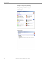
The Simulation/Loopback Test icon
is displayed at the bottom left of the
Operator faceplate, indicating the device is in simulation.
When you have finished in simulation, set the Inp_Sim parameter in the
controller to ‘0’ to return to normal operation.
Execution
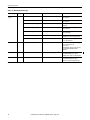
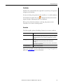
The following table explains the handling of instruction execution conditions.
Condition
Description
EnableIn False (false rung)
Processing for EnableIn False (False Rung) is handled the same as if the Analog
Output were disabled by command. The CV output is de-energized (zeroed) and the
Analog Output instruction is shown as disabled on the HMI. The mode is shown as
No mode.
Powerup (prescan, first scan)
Processing of modes and alarms on prescan and powerup is handled by the
embedded P_Mode and P_Alarm instructions. Refer to their manuals
for details.
On powerup, the analog output ownership is cleared; otherwise, all data remains in
the state it was in at power down.
Postscan (SFC transition)
No SFC postscan logic is provided.
Refer to the Logix5000 Controllers Add-On Instructions Programming Manual,
publication 1756-PM010, for more information.
Rockwell Automation Publication SYSLIB-RM011E-EN-E - August 2014
21