1
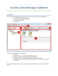
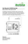
HelpAndManual_unregistered_evaluation_copy
SC Series Controller
User Manual
Model SC24, ACC-SYS-0024
Model SC36, ACC-SYS-0036
Table of Contents
SC24-36 Controller
1
Introduction
...................................................................................................... 1
Controller Components
...................................................................................................... 1
Controller Installation
2
Mounting the Controller
...................................................................................................... 2
Connecting the Valves
...................................................................................................... 3
Connecting a Master
......................................................................................................
Valve, Flow & Pressure Meter
4
Connecting a Pump
...................................................................................................... 4
Connecting the power
......................................................................................................
source, and ground
5
Connect a Rain Sensor
...................................................................................................... 5
Getting Started
6
Sprinkler System ......................................................................................................
Basics
6
About the Sensor......................................................................................................
Sensor.............................................................................................................
Installation
Sensor.............................................................................................................
Configuration
Timer Programs ......................................................................................................
6
7
8
9
Sensor Programs...................................................................................................... 9
Planning a Water......................................................................................................
Schedule
9
Controller Programming (basic)
Auto/Run
10
...................................................................................................... 10
Set Time & Date...................................................................................................... 10
Off-Add or Remove
......................................................................................................
Hardware
11
Water Schedule...................................................................................................... 12
Watering Start Times
...................................................................................................... 13
Soil Moisture Sensors
...................................................................................................... 13
Zones
...................................................................................................... 14
Controller Programming (advanced)
Soak Cycle
15
...................................................................................................... 15
Flow Management
...................................................................................................... 15
Test
...................................................................................................... 17
Event Pause
...................................................................................................... 18
Advanced Options
...................................................................................................... 19
Water Budget/Rain
......................................................................................................
Delay
21
Glossary
21
My Irrigation Schedule
HAVE A QUESTION, PROBLEM, OR COMMENT?
Our toll-free Technical Service phone number is 866-887-1470
25
Limited Product Warranty
HAVE A QUESTION, PROBLEM, OR COMMENT?
Our toll-free Technical Service phone number is 866-887-1470
27
Installation and Operation Manual
SC24-36 Controller
Introduction
Congratulations on your purchase of the Acclima SC24/36, the finest soil moisture
sensor irrigation controller on the market. You have joined in conserving water—earth's
most important resource.
Suspended Cycle™ Irrigation
The Acclima SC24/36 is a Suspended Cycle™ irrigation controller that utilizes advanced
Acclima Digital TDT™ soil moisture sensors that report accurate soil moisture readings
to the controller regardless of soil type, temperature, compaction or soil chemistry. Like
conventional controllers the SC24/36 uses watering schedules to determine when a zone
will irrigate, but unlike conventional controllers the zone will not water during a given
watering cycle if there is already sufficient moisture in the soil.
At the beginning of each programmed watering cycle the controller takes a moisture
reading from the sensor governing that program. If the moisture is above the 'watering
threshold' you have set for that program, the watering cycle will be suspended until the
next programmed start time. If the moisture level is below the 'watering threshold' then
the full cycle will run as programmed.
During wet or cool periods you will notice less watering activity from your Acclima system.
During hot, dry periods you will notice more watering activity.
The Acclima SC24/36 is an advanced controller allowing you to maximize the efficiency
of your sprinkler system. The controller allows for simultaneous multiple zone watering
based on your settings. You have the flexibility to set each zone to run on a conventional
timer program or on a sensor-controlled program. These options allow for customization
of the controller to your unique sprinkler system.
Controller Components
1. LCD Display
2. Controller SOFT buttons – The button's function
varies with each screen.
3. Controller Adjustment buttons (Press and Hold to
repeat)
4. Front Cover – The front cover is weatherproof and
includes a security lock.
5. Controller Dial
Auto/Run – The normal
position for automatic
irrigation. The controller will
run in any knob position
except the OFF position.
Off – Add/Remove Hardware – Shuts the system down. This position is also used to
install or remove sensors and flow meters.
Watering Schedule – Knob position for setting the days or schedules on which each
watering Program will run.
Watering Start Times – Knob position for setting the start times for each watering
Program.
Page 1
SC24-36 Controller
Soil Moisture Sensors – Knob position for setting sensor thresholds and for manually
reading the sensors.
Soak Cycle – Knob position for setting soak cycle run and soak durations for each zone.
Flow Management – Knob position for setting zone and tap water flow rates for
automatic management of simultaneous zone watering.
Test – Tests valve solenoid currents, wire leakage, sensor currents and valve operation.
Allows sequential activation of zones for checking sprinkler heads.
Event Pause – Knob position for programming future events during which you do not
want watering to occur.
Advanced Options – Knob position for adjusting display contrast, setting up multiple
zone watering, reading messages, etc.
Water Budget/Rain Delay – Knob position for setting seasonal adjustments and rain
shutoffs for clock driven zones that do not utilize sensors. Sensor zones accommodate
weather conditions automatically.
Zones – These positions access each individual zone and are used for assigning the
zones to programs, for setting zone run times and for manually watering zones.
6. Pull tabs to access inside wiring terminals.
Controller Installation
Mounting the Controller
1. For safe, reliable operation select an installation site which will provide:
Protection from direct irrigation spray
Protection from direct sunlight during the hottest part of the day
Access to a 110 volt circuit that is not controlled by a light switch nor feeds a noisy load
such as a large motor.
Access to a #6 to #10 grounding wire and copper clad ground rod.
Access to the sprinkler control valve wiring.
2. Securely mount the controller through the stud mounting locations or the optional
masonry mounting hole using appropriate wood screws or concrete anchors (not
included).
NOTE: If installation will be on drywall or masonry, install screw anchors to assure secure
mount.
3. Use a 1/2" metal
conduit coupling to attach
a connection box to the
power nipple on the
bottom of the controller as
shown in the diagram
below.
4. Drill a hole in the
bottom of the controller
box to install a 1/2"
conduit for the ground
wire as shown below.
Page 2
Installation and Operation Manual
NOTE: Conduit, adapters, grounding rod, and wires are not provided. Install conduit and
adapters as required by local electrical codes.
5. Clip out the knock-out from the
large hole in the bottom of the
controller and install a 3/4" conduit
for the zone wires. If a larger hole
is needed use a hole saw to
enlarge the provided hole. The
knock-out can be used to guide
the drill bit for the hole saw.
Connecting the Valves
Each zone has a valve that controls the flow of water to the zone. Control wires from
these valves must be connected to the controller.
1. Route the valve wires from the valves into the controller as depicted in the schematic
below.
2. Attach the common wire to one of the 4 common terminals. Tighten down the screw.
3. Strip the insulation from the zone wires back 1/2". Push the zone wires into the push-in
terminal strips. If you need to remove the wire press the black lever on the terminal strip
with a screwdriver then pull out the wire.
4. If you are using a pump with your sprinkler
system connect the pump relay wire to the
terminal labeled 'Pump'. If you are using a
Master Valve with your system connect the
wire from the master valve to the terminal
labeled 'MV'. Note that the pump can be
configured to turn on with selected zones.
The Master Valve turns on with all zones.
NOTE: If you are installing an Acclima Flow and Pressure Meter the Master Valve will be
connected to the black wires on the Flow and Pressure Meter module rather than to the
controller.
Page 3
Controller Installation
WARNING: Insure that all wire connections in your valve boxes are protected with
waterproof connectors such as the 3M DBY connectors.
Connecting a Master Valve, Flow & Pressure Meter
The Acclima SC 36 enables sophisticated flow control for simultaneous multiple zone
watering. Knowing the available flow rate from your water source, it can then water
multiple zones simultaneously without causing a pressure drop in your system. If you
know the flow rates of your zones and your water source you can enter this information
into the controller and activate this feature even though you do not have a flow meter
installed. If you install an Acclima Flow and Pressure Module the controller will determine
this information automatically.
1. Install the Flow and Pressure Meter (FPM) module in accordance with the provided
instructions.
2. Connect the black wire pair from the FPM module to the Master Valve.
3. Connect the Red and Black wire pair from the
FPM module to the Data Industrial Flow
Transducer- red to red and black to black.
4. Connect the white wire from the FPM to the
common wire in the underground wiring system.
5. Route the remaining red wire from the FPM
back through the zone wire conduit to the MV
terminal in the SC 36 controller.
NOTE: Connecting the master valve is optional and may not be required for your
irrigation system.
Connecting a Pump
Connect one of the pump relay wires to the common
wire at any convenient access to the common. Run
the remaining wire back through the zone wire conduit
and connect it to the 'Pump' terminal as shown below.
Page 4
Installation and Operation Manual
Connecting the power source, and ground
WARNING: AC power wiring must be installed by
qualified personnel only. All electrical components
and procedures must comply with all applicable local
and national electrical codes. Make sure the power is
OFF before connecting to the controller.
1. Route the power wires through a ½" conduit
coupling and into the connection box. Make the
connection in the connection box with wire nuts and
close the box cover.
2. Route a #6 to #10 grounding wire through a ½"
conduit between the 'Ground' terminal and an
outside copper-clad grounding rod.
3. Apply power to the controller.
Connect a Rain Sensor
Often a rain storm will not provide enough water to bring soil moisture levels up to the
needs of the grass. If a program starts during a rainstorm and the soil is dry at the root
zone, the controller will irrigate for the full duration of the watering time. If the rainfall is
heavy and has soaked to the root zone by the time of the program start, the controller will
not allow watering. Hence, a rain sensor is not needed and is not desirable for the
system. However, some municipalities insist that rain sensors be installed on automatic
irrigation equipment. If you live in such an area connect the rain sensor to the two 'rain
switch' terminals on the controller. You will need to remove the jumper wire first.
After installing the rain sensor press the button beneath the LCD Labeled "Rain Sensor"
to activate it.
Page 5
Getting Started
Getting Started
Sprinkler System Basics
There are four main components to an Acclima SC24/36 automatic system, controller,
zone valves, sprinklers, and soil moisture sensors. The following is an example of a
typical installation.
Valve 1 – Zone One – Front
Side Lawn - Sensor Program
(S1)
Valve 2 – Zone Two – Front
Lawn – Sensor Program (S1)
Valve 3 – Zone Three – Side
Shrubs – Timer Program A
Valve 4 – Zone Four – Garden –
Timer Program B
Valve 5 – Zone Five – Back
Lawn – Sensor Program (S5)
The controller signals the zone valves when to start and stop the flow of water to the
sprinklers. The sensors communicate the soil moisture level to the controller, and the
sprinklers apply the water.
Each zone valve controls a group of sprinklers called a zone. The zones should be
planned and installed according to microclimates or the types of plants or turf being
watered, the sun/shade conditions, the amount of water delivered by the sprinklers and
the available water flow and pressure.
The watering schedule determines when and how long each zone will be watered. The
SC24/36 uses two types of watering schedules, timer programs and sensor programs.
The SC24/36 provides four independent timer watering programs (called A, B, C and D)
and up to 24/36 sensor programs (called S1, S2, S3…S24/36). Each zone is assigned to
one sensor Program or to one or more timer programs.
(except in cases of soak cycles and multi-zone watering). This is called a watering cycle.
About the Sensor
The Acclima Digital TDT™ soil moisture sensor accurately measures the volumetric
water content in the soil and communicates it to the controller.
Soil moisture is reported as a
percentage of water by volume. The
sensor automatically takes an
average moisture reading
over the length of the stainless steel rods every time a sensor program is scheduled to
Page 6
Installation and Operation Manual
begin and whenever a manual reading is required. For example, if the sensor were
dipped half way in a bucket of water the moisture reading would read 50%.
Sensors are buried in a representative place in an irrigation zone at a depth of about 4
inches. A representative place means a spot in an irrigation zone that represents the
conditions of the whole zone and other zones that the sensor will control. If the zone is
only partially shaded the spot should be in the sun. The spot should be in a low traffic
area and away from tree roots and sprinkler heads. It must not be in a low spot where
water will accumulate. The subsoil beneath the sensor must allow drainage. Do not install
sensors near the base of slopes or near sidewalks, hose connections or car-washing
areas. It is a good idea to have a sensor near the top of a south or west facing berm or
slope or any other area where stress to the grass has been a problem. Do not install
sensors in a location that will receive water for a zone that is not controlled by that
sensor.
In order to save digging a trench from the sensor back to the controller Acclima has
developed a wiring method that allows you to connect the sensor to your irrigation system
at the nearest valve box.
Sensor Installation
1. Before you start ensure the lawn has been watered deeply so that the digging will be
easier and the excavated turf will not be subjected to undue stress.
2. With a flat shovel cut a U shaped vertical slit in the turf – 24 inches square and about 4
to 6 inches deep.
3. Work your shovel under the turf to a depth of 4 inches and roll it back toward the
hinged or uncut side.
4. Lay the sensor in the soil in the bottom of the hole and press it down so that it is
seated firmly in the soil in the bottom of the hole. Remove any rocks and sticks that
may interfere.
5. Pack loose soil around and between the sensor rods, covering them with tight soil to a
depth of at least 1/2 inch. Compact the soil around the rods to the same compaction
as the undisturbed soil.
6. Cut a deep vertical slit out of the side of the hole for the sensor wires. Poke the wires
down to the bottom of the slit. Keep the wires away from the sensor rods.
7. Replace the rolled-over sod. Pack around the edges with your fists and seal up the
cracks as much as possible.
To connect the sensor wiring do the following:
1. Install a 6 inch wiring box near the sensor where you will make a splice for running
longer wiring to the nearest valve box. This splice box will also serve to mark the
approximate location of the sensor for many years ahead after you have forgotten
where you put it.
2. Bring the 3 sensor wires up underneath the splice box. Also bring three 14-Ga
polyethylene insulated wires (red, white and black) underneath the splice box. These
will run to the nearest valve box.
3. Cut a deep slit trench from the splice box to the valve box and tuck the 3 wires into the
bottom of the trench. Run the 3 wires underneath the lower lip of the valve box. Stomp
the slit trench closed with your feet.
4. Wire the sensor to the extension wires in the splice box. Use waterproof connectors
such as 3M DBY connectors to seal the connections.
5. In the valve box disconnect the solenoid wires from the present wiring if wiring is
already installed. One of the solenoid wires will have been connected to the common
wire from the controller and the other will have been connected to the zone wire from
the controller.
6. Connect the black wire from the senor to one of the valve wires.
Page 7
Getting Started
7. Connect the white wire from the sensor and the other wire from the valve to the
common wire.
8. Connect the red wire from the senor to the zone wire that you disconnected from the
valve. Use DBY connectors to make these 3 connections.
Sensor Configuration
Once the valve wires are connected to the controller scan for hardware using the Off Add/
Remove Hardware feature (see page 16). The controller will locate the sensor
automatically and properly configure the system. The sensor is now wired into the system
and ready for use.
Sensor Thresholds
Soil acts much like a sponge. When you immerse a sponge in
water and repeatedly squeeze it, it becomes saturated. If you
remove it from the water it will drain rapidly then drip for a while.
Gravitational forces act against capillary forces until equilibrium is
reached and the sponge stops dripping. This equilibrium state is
called 'Field Capacity' (FC). There is still plenty of water in the
sponge but gravitational forces are not strong enough to pull it out.
When soil is at field capacity and slightly below conditions are
excellent for plants. The addition of water above field capacity
wastes water, causes leeching, and
depletes the soil of valuable nutrients, while also contaminating the groundwater with
pesticides and fertilizers. It also drives oxygen out of the soil and suffocates the roots.
As soil dries out from field capacity a point is reached where plants have difficulty
drawing water out of the soil and begin to experience stress. This lower limit to which you
can allow your plants to experience is called 'Management Allowable Depletion' (MAD).
This is the point where irrigation water must be applied to keep the plants from
experiencing stress. If water is not applied the soil will dry to the 'Permanent Wilt
Point' (PWP). This is the point at which the plant dies.
The proper moisture zone for healthy plants is between Field Capacity and Management
Allowable Depletion. Management Allowable Depletion is typically 75% of Field Capacity
in absolute volumetric water content terms. The Acclima sensor measures absolute
volumetric water content. Field Capacity can easily be determined by flooding the sensor
Page 8
Installation and Operation Manual
area then waiting for the sensor readings to stabilize. The stabilized reading is Field
Capacity. For heavier, low-percolation soils it may be best to flood the sensor in the
evening then take a moisture reading the next morning before transpiration starts (before
the sun gets too high). In the morning the soil will be at Field Capacity.
After you have determined the FC for each sensor multiply that number by .8 to get the
watering threshold. Using .8 instead of the .75 MAD level will provide margin for the
sustenance of the grass until the next watering cycle. Round up to the nearest whole
percent then set that number as the 'threshold' for the sensor.
Field Capacity %
Watering Threshold %
15
12
20
16
25
20
30
24
35
28
40
32
45
36
NOTE: Run the system on timer programs (programs A, B, C, and D) for a week after
flooding the sensors. Otherwise the flooded sensors will not allow the dryer lawn to
receive water. After the week period configure the zones to run on the sensor programs.
Timer Programs
The SC24/36 allows four timer programs (called A, B, C and D). Timer programs are
used when you do not want a zone to track a moisture sensor. This will be helpful for
xeriscape, gardens, or flower beds where you may not have a sensor installed.
Timer programs begin as scheduled, water for a set duration, and then turn off. You can
customize timer programs to water daily, odd days or even days, or every 3 to 30 days.
You may also customize timer programs to water on selected days of the week. Each
timer-configured zone can run one or more timer programs.
Sensor Programs
The SC24/36 accepts up to 36 sensors. Each installed sensor creates a new program
(S1, S2, S3…S36). Any zone can be configured to follow any sensor program.
Sensor programs are controlled by a specific soil moisture sensor buried somewhere
among the zones assigned to that program. A moisture threshold is set for the senor and
a schedule for the program is set up. This includes setting the days to water, the program
start times and the zone run times. Sensor programs should be set to water frequently—
every day if possible. On those days when water is not needed no water will be applied.
But if water is needed the next cycle is only hours away. If you must restrict watering to
widely spaced intervals set the thresholds a little higher to allow stress-preemptive
watering ahead of those dry spells.
Each sensor-configured zone must be assigned to only one sensor program.
Planning a Water Schedule
Watering schedules consist of four data points:
·
·
·
·
What days to water—watering days
When to water—start time
How long to water—run time
Sensor threshold (for sensor programs)
Page 9
Getting Started
It is always helpful to plan your watering schedule on paper before beginning the
programming steps. Your will have a record of your watering schedule and zone locations
which can be kept with your controller after it is installed.
Controller Programming (basic)
Auto/Run
The Auto/Run setting on the controller dial is the normal operating position. The system
is in auto mode and the screen displays error messages, current watering activity, and
current zone activity.
1. Press the Next and Prev buttons to
navigate through the fields.
2. Press the + or - Adjust Value to
select fields or edit values.
View Current Watering Activity
This screen displays a list of all zones, programs, and their status. It is useful to view
which programs and zones are currently active and which tasks are pending. If one
program is active and another program starts, the controller stacks the new program
tasks behind the active program. Once the current program is finished the controller will
service the next program.
Set Time & Date
Before programming the irrigation controller the date and time should be set.
1. Turn the controller dial to Set Time
and Date. The current or default date
and time are displayed.
2. Press the Prev and Next buttons to
move through the fields.
3. Press the Adjust Value buttons to
change the new date and time.
4. Press the SAVE soft key to save the
time and date you have entered.
Page 10
Installation and Operation Manual
Off-Add or Remove Hardware
The Off Add/Remove Hardware mode has two functions:
1. To place the controller in OFF Mode
2. To facilitate Hardware Setup
When you select Off Add/Remove Hardware the controller takes 4 seconds to shut down.
This is done so that turning the knob through this position will not unintentionally turn off
the controller.
In Off Mode the controller is OFF and will not water. The controller display shows the
Hardware Setup Screen.
In Hardware Setup the controller automatically scans and detects hardware installed
throughout the system. It is necessary to scan the system and detect hardware whenever
sensors are installed or removed. The controller will also detect any installed Flow and
Pressure Meter.
Every installed sensor will cause the controller to
create a new Program associated with that
sensor. You will then configure that Program with
watering days and start times. Any of the zones
can then be assigned to that Sensor Program.
The zone that waters the sensor must be
assigned to that Program.
For example, in the screen at the right notice that the terminal for zone 2 is wired to a
sensor. That sensor will be called Sensor 2 and the controller will create a Program for it
called S2.
If you press (+) the controller will scan the highlighted terminal for hardware. If you press
(-) all terminals will be scanned for hardware.
Page 11
Controller Programming (basic)
Water Schedule
The Watering Schedule knob position allows you to modify the days of each watering
program. This includes both timer programs (A, B, C, and D) and sensor programs (S1,
S2, S3…S36).
1. Select a Program by pressing the + or - Adjust
Value buttons in the Select Program field. Timer
programs are A through D and sensor programs
are S followed by the zone terminal number
where they are installed.
Next button to move to the Day
2. Press the
Cycle Type field. This field allows you to select
the day the selected program will water.
Custom: choose which days the program waters.
Everyday: allows the program to water everyday.
Odd Days: allows the program to water only on odd calendar days.
Even Days: allows the program to water only on even calendar days.
Every__ Days: allows you to select how many days between watering from every 3 day
to every 30 days.
3. Press + or - Adjust Value buttons to select the day cycle type.
4. To adjust Custom day cycle type press Next and scroll through the days of the week.
The program will water on days of the week showing a water drop and will not water on
days of the week showing an X. Use the + or - Adjust Value buttons to change from a
drop to an X.
5. Follow the same instructions for all desired programs.
NOTE: Though sensor programs are set to water on a day cycle, they may or may not
water due to soil moisture levels.
Manual Program Start allows you to run a full program manually. To do this highlight
the Select Program field using the Next and Prev buttons. Then select the program you
wish to run using the + or – Adjust Value buttons. To start the program press the
Manual Start soft key.
Note: The Manual Start Program feature will run all the zones for their full duration as
set up in the program. Any other program that may be running at the time you start will be
suspended and will finish after the manual program finishes. If another program is
scheduled to start while a manual program is running, it will be delayed until the manual
program is finished. Multiple program starts can be initiated. They will run in the order
they were initiated and take precedence over scheduled program starts. A given program
can be stacked for manual watering only once. Manual program watering uses the same
flow control settings as does normal scheduled program watering.
Page 12
Installation and Operation Manual
Watering Start Times
Watering Start Times allows you to select when each program begins to water. Each
program can have up to 6 start times. Setup is the same for both timer programs (A, B,
C, and D) and sensor programs (S1, S2, S3…S36).
1. Press the + or - Adjust Value buttons to select
which program start times you want to setup.
Next and
Prev buttons to
2. Press the
move between each of the 6 start times.
3. Use the + or - Adjust Value button to select
the desired start time.
Soil Moisture Sensors
Soil Moisture Sensors enable you to adjust the moisture thresholds for each sensor in the
system and take a sensor reading. Sensors read and display:
· Soil Moisture – reported as percent moisture by volume
· Soil Temperature in degrees Fahrenheit
· Soil Conductivity reported in deci-Siemems per meter (dS/m).
The default soil moisture threshold is 25%. You should adjust your thresholds based on
your unique soil conditions in accordance with instructions at page 13-14.
1. Press + or – Adjust Value to select the
sensor.
2. Press Next to move to the threshold field and
use the + or - Adjust Value buttons to change
the threshold.
3. To read the sensor press Next to move to the
Read Sensor field and press the + Adjust Value
button to take a sensor reading.
After a few seconds the sensor reports the current soil moisture, temperature, and
electrical conductivity at the sensor.
Page 13
Controller Programming (basic)
Zones
Once the timer programs, (programs A, B, C, and D) and the sensor programs (programs
S1, S2, S3…S36) are set up you need to assign the zones to the programs. Each zone
can be set to follow one or more of the timer programs or one sensor program.
Zone setup allows you to adjust:
Enable Zone for Watering, yes or no
Zone watering mode, timer or sensor
Run Time in minutes
Manually run the zone
For Timer Programs (programs A, B, C, and D) you can set the zone to follow one or
more of the four timer programs.
1. Turn the controller dial to the numbered
Zone Run Times/Manual Watering settings.
Each setting controls 1 of 3 zones. Press the
third soft key labeled Zone Select to select
one of the three zones.
2. Press the Next or Prev buttons to move
between the program fields.
3. Press the + or - Adjust Value buttons to
change the run time of each program in
minutes.
For Sensor Programs (S1, S2, S3…S36) you can set the zone to follow one sensor
program.
1. Press the Next or Prev buttons to move to the
Zone Watering Mode.
2. Press the + or - Adjust Value buttons to
change the zone watering mode to sensor. This
will only be possible if there is a sensor installed
on the system.
Next button to move to the
3. Press the
Controlling Sensor field.
4. Press the + or - Adjust Value buttons to
change the Controlling Sensor field to select
which sensor
program you want the zone to follow.
Next button to move to the Run Time field.
5. Press the
6. Press the + or - Adjust Value buttons to change the Run Time field to select the
zone's run time in minutes.
Manual Run Time allows you to set the time that the selected zone will run manually. To
set the run time and manually start a zone do the following:
Next or
Prev buttons to move to the Manual Run Time field.
1. Press the
2. Press the + or - Adjust Value buttons to adjust the Manual Run Time minutes.
3. Press the Manual Start soft key to start watering.
Page 14
Installation and Operation Manual
NOTE: The manual zone will begin watering immediately and will cause any other
watering activity to be postponed until the manual zone is finished. The manual watering
for the zone can be terminated by pressing the Manual Stop soft key. If you rotate the
knob to another zone and start it manually, the added zone will run in its turn. Multiple
manual zone starts can thus be stacked but a given zone can appear in the list only once.
Manual zone starts take priority over manual program starts and manual program starts
take priority over scheduled program starts. Any postponed activity will return to
automatic run mode after all manually started zones have finished. The run time for
manually started zones is the manual run time programmed in the zone setup. Manual
zone watering for multiple zones uses the same flow control settings as does the normal
scheduled program watering.
Controller Programming (advanced)
Soak Cycle
NOTE: This option provides advanced control of the irrigation, and is not required for the
controller to operate.
A Soak Cycle is used for hillsides or slopes to avoid surface runoff by watering for a short
period of time, stopping and allowing the water to soak in, then continuing another short
period of time until the total zone run time is satisfied. A soak cycle consists of two parts:
a maximum on time and a minimum off time.
1. Use the + or - Adjust Value buttons to select
which zone you want to run in soak cycle.
2. Press Next to move to the maximum time on
field and press the + or - Adjust Value buttons to
set the maximum on time.
3. Repeat for the minimum time off field.
The Acclima SC24/36 has advanced multiple zone watering functions. If a zone is in a
soak cycle and another zone is scheduled to follow, the controller will initiate irrigation in
the following zone during the soak cycle "Off" period. The "Off" time period will
automatically increase to allow the following zone to complete its irrigation cycle before
control returns to the soak cycle zone.
Flow Management
NOTE: This option provides advanced control of the irrigation, and is not required for the
controller to operate.
The Acclima SC24/36 is equipped with an advanced Flow Management System. The
controller incorporates simultaneous multiple zone watering to automatically optimize the
total water flow from your water source. This feature minimizes your overall irrigation
time, makes it possible to 'get through' your watering schedule on larger, more complex
properties, and provides uniform loading on pumps.
Page 15
Controller Programming (advanced)
Flow Management aligns the total zone water consumption to be as high as possible
without exceeding the capacity of the water source. Up to four zones will run
simultaneously to achieve this flow rate. That zone limit can be modified under the
Advanced Options knob position. Setting up Flow Management requires providing the
controller with zone flow rates and the water source flow capacity. If you have installed a
flow meter the controller will 'learn' the flow rates of the zones automatically. If you do not
have a flow meter on the system you must enter those rates using the Zone Water
Management screen. The source flow capacity is entered in the main Flow
Management screen as follows:
1. Enter the Master Valve Pipe Diameter (main
Next button and
line pipe diameter) using the
the + or - Adjust Value buttons. The controller
automatically calculates the Available Water
Supply in gallons per minute (GPM). This
calculation is based on the standard
recommended flow velocity of 5 feet per second.
You can override this calculation and enter your
own GPM rate if you wish by selecting the
Available Water Supply field and adjusting the
value.
2. Some valves have difficulty turning off if another valve immediately turns on and drops
the water pressure. Set the lapsed time you need between valve turn-off and the next
valve turn-on in the Valve Delay field. This field is also useful for setting long valve
delays needed for recharging a pond or a poor well.
3. Normally you will want to have the Master Valve remain on during a valve delay period
but if you are using the Master Valve wiring to activate a pond pump and need recharge
time set the Master Valve to Off during valve delay. Do this in the Master Valve During
Valve Delay field.
4. The emergency shutoff field will only be available if there is a flow meter installed. It
will shutoff the system if the flow rate is exceeds the set rate.
The Zone Water Management screen can be accessed from the Flow Management
screen using the Select Item buttons and + button.
Press the Prev button to switch to the Zone Water Management field and press +
Adjust Value.
This Zone Water Management screen displays a
report of each zone and its water usage. The
default value for each zone's water usage is
"unknown." If you install a flow meter, after you run
the system for the first time the controller will
automatically measure flow rates for each zone
and the "unknown" value displayed will be replaced
by the actual flow rate determined by the
controller. If you know the flow rates for each zone
you can manually enter the values into the system.
Once the system knows the rate the water source provides and the rate each zone uses,
it will automatically maximize the use of your water source based on these settings.
Page 16
Installation and Operation Manual
For example, if the water source provides 80 GPM of water, and program S1 includes 4
zones, each using 20 GPM, the system will water all four zones simultaneously at the
program start time. If program S2 includes 3 zones, each using 40 GPM, the system will
water the first 2 zones for the programmed time simultaneously and the third zone by
itself thus maximizing the water source.
Notice the message near the bottom of the display. The system will alert you if the zone
will be used in multi-zoned watering. The default "unknown" value prohibits multi-zone
watering for that zone and the message reads: "This zone will water alone." If a number
has been entered into the Zone Water Use field then the message will read: "Multi Zone
Watering Possible."
Press the Back soft key to return to the Flow Management screen.
Test
NOTE: This option provides advanced control of the irrigation, and is not required for the
controller to operate.
The Test function provides access to two additional screens that help you diagnose
wiring and hydraulic problems with your irrigation system. The main screen tells you the
condition of the back-up battery and the box temperature.
If the displayed Battery Voltage drops to 2.2 volts or below replace the battery with two
Alkaline AA cells. Do this with the power on so that you will not have to reset the clock.
The battery compartment is on the back edge of the pull-out panel. Remove the battery
cover and replace the batteries noting the proper polarity.
The Box Temperature should not be allowed to exceed 150 degrees Fahrenheit. High
temperatures will cause the display to stop working properly and in the extreme could
melt the box. The internal transformer heats the box 10 to 20 degrees above its
surrounding temperature. Do not mount the box in direct afternoon sunlight. If it is to be
mounted in another enclosure make sure that the enclosure is ventilated. Use a metal
conduit and power junction box for connecting the 110 VAC power. The metal will help
pull the heat out of the transformer. .
Test Valve Current
To perform an electrical test on the system wiring and solenoid valves use the Next and
Prev buttons to access the Test Valve Current field. Then press +.
Immediately the controller will begin measuring solenoid current, sensor current and
leakage current on each of the 36 zone terminal circuits and on the master valve and
pump terminals. You can scroll through the results using the Next and Prev buttons. If
you want to verify a reading you can press the + button and the highlighted terminal will
be tested again.
Valve current varies by manufacturer but is generally in the 180 to 250 mA range. If it is
below 100 mA or above 350 mA you probably have a failing valve. The controller is
designed to operate loads up to 600 mA. If the current exceeds 600 mA, replace the
solenoid immediately.
Sensor current is typically 40 mA. If a sensor is not working and its current is above 50
mA or below 25 mA then it needs replacement, provided the wiring leading to it is
insulated, securely fastened and unbroken.
Leakage current is the current that flows through the ground between a zone wire and
Page 17
Controller Programming (advanced)
the common wire due to missing insulation on the wires. This can cause communications
errors between the controller and sensors and will eventually cause the wires to corrode
away and system failure. This current should read 0 (-----).
Press the Back button to return to the main Test screen.
Walk-Around Test
To test the watering operation of all of the zones in your system use the Next and Prev
buttons to highlight the Walk Around Test field then press +.
The Walk Around Test screen will appear. You can set the amount of time that each
zone will run in the Runtime for Each Zone field. You can access this field using the
Next and Prev buttons and then set the run time with the + and – buttons. The starting
zone appears in the Testing Zone field which defaults to zone 1. If you want to start at a
higher zone use the Next and Prev buttons to access the Testing Zone field and set the
starting zone with the + and – buttons.
After you have set up the timing and starting zone use the Next and Prev buttons to
return to the Start Test field and press +. Only zones with a valid runtime will operate.
Unconfigured zones or disabled zones will be skipped.
As the zones sequentially turn on you can 'walk around' with the pattern and inspect for
broken sprinkler heads, clogged heads, miss-operating valves, incomplete spray
patterns, and etc.
4. Press the Back soft key to return to the Test screen. Pressing Back or rotating the
knob will cancel any test that is in progress.
Event Pause
NOTE: This option provides advanced control of the irrigation, and is not required for the
controller to operate.
Event Pause enables the system to pause operations for up to 6 scheduled events. This
is especially useful for scheduled social and sports events where irrigation must be
suspended without turning off the system or adjusting the programs (risking forgetting to
restore it).
Next and
Prev
1. Select events from Event #1 through Event #6 by using the
buttons, then press + Adjust Value.
Next and
Prev buttons to move between fields and the + or - Adjust
2. Use the
Value buttons to change the Start Date, the date of the event, the Start Time, the time of
day the event begins, and the Duration, how long the even will last.
Page 18
Installation and Operation Manual
3. Once the desired event is set press the
Next button to move to the Save Changes field
and press + Adjust Value. Or you can press the
soft key below the save changes icon near the
bottom of the display.
4. To cancel changes move the Cancel Changes
field and press + Adjust Value, or to delete the
even move to the Delete This Event field and
press + Adjust Value.
Pause
To immediately pause all watering highlight the Current Pause Duration field using the
Next and
Prev buttons. Use the + Adjust Value button to set the pause time in 5
minute increments. The pause will begin immediately. To return to automatic watering
press the Resume Auto soft Key.
Advanced Options
NOTE: This option provides advanced control of the irrigation, and is not required for the
controller to operate.
The Advanced Options are miscellaneous systems settings and messages. They are:
·
·
·
·
LCD Contrast Adjustment
Maximum Zones On, for multi-zone watering default 4
Read/Clear Status Messages
Erase Controller Memory
LCD Contrast Adjustment: Use the Next and Prev buttons to highlight the LCD
Contrast number. Then use the + and – buttons to adjust the contrast to your liking. The
default setting is 50.
Maximum Zones ON: Use the Next and Prev buttons to highlight this area then use the
+ and – buttons to set the maximum
After Power Failure Reset/Recover Mode: Reset Mode, causes the controller to ignore
any watering during the power failure and resume the schedule when the power returns.
Recover mode, causes the controller to resume any watering in progress during the
power failure and scheduled watering during the power failure. The controller catches up
on missed watering.
Read/Clear Status Messages: Periodically you should check the status messages
associated with your system. The Auto/Run knob position also displays a line indicating
the number of status or error messages. If you are troubleshooting the system you will
want to look here to determine what the system knows about the problem you are
pursuing. Following is a list of potential messages:
Ribbon Cable Unplugged: This is a fatal condition. The SC24/36 cannot operate due to
an unplugged cable. The ribbon cable is behind the front panel. It should be plugged into
the upper socket in the plastic slot. If the cable is ok then some other error exists and the
controller will need factory attention.
Page 19
Controller Programming (advanced)
Power Overload: There is a short circuit in one of the zone valves, in the zone valve
wiring or on the valve board in the SC24/36. Check for a shorted solenoid valve for the
zone or zones listed, and then check the valve and board wiring.
Shorted Valve: A valve connected to a sensor or flow meter is shorted. Check the
solenoid indicated.
Pipe Break: The flow rate is excessively high. This could point to a broken zone pipe or
missing sprinkler head. It could also point to a stuck valve. Check the indicated zones for
plumbing problems.
Main Break: The flow meter continued to read high when all valves are off. The main line
is broken or a valve is stuck. Check the mains and look for zones that are running without
being turned on.
Communications Error: The remote device (sensor or flow meter) is not communicating
properly with the controller. Infrequent errors are ok, but if they are regular and persistent
check the device wiring. Especially check for un-insulated wiring and loose wire nut
connections. If that is ok suspect the device.
Dead Battery: This means that the battery was dead during a power fail and the SC24/36
clock lost track of the time. You will have to replace the batteries and reset the clock.
Scheduling Overflow: The controller was not able to keep up with an aggressive watering
schedule. The list of pending zones to be watered when a program starts, the valves
operate one at a time in numeric order with each zone watering completely before
another zone begins
was dumped. Check your program scheduling for congestion. Insure that the daily
watering load does not exceed the available time.
Power Restore. Failed at TIME: A power failure occurred at the time indicated and was
restored. If the power was off for an extended period there may be zones that did not
receive water, depending on reset/recover mode.
To access, read and clear the Status Messages do the following:
Next and
Prev buttons to
1. From the Advanced Options screen press the
highlight the Read/Clear Status Messages field. Then press the + button. The message
list will appear.
Next and
Prev buttons to scroll through the messages.
2. Use the
3. If you wish to clear the messages press -.
4. Use the Back button to return to the Advanced Options screen.
WARNING: Erase Controller Memory
Don't do this unless you intend to clear out all configurations, settings, logs,
activities and messages. This is intended only for re-using the controller in a
different site, for training or for re-doing an installation.
Page 20
Installation and Operation Manual
Water Budget/Rain Delay
NOTE: This option provides advanced control of the irrigation, and is not required for the
controller to operate.
Water Budget (seasonal adjustment) and rain delay allow you to adjust the timer zones
(programs A, B, C, and D) for seasonal changes and rain.
Water Budget is a seasonal adjustment that changes the run times of all timer zones as
a percentage. For example, if the controller is set in the spring during the summer
months of June, July, and August the user might set the water budget for those months
at 150%. Meaning the zone run times will be 1.5 times the programmed duration. If the
zones were watering for 10 minutes they will all run for 15 minutes during those months.
Another example would be setting the controller in the summer and changing the water
budget for the cooler fall months of September and October to run at 50%. Meaning the
zone run times will number of zones that you want to water simultaneously under the
Acclima Flow Management System. The acceptable range is 1 to 4.
1. Press the Next button to move to Water Budget
Select Program and press the + or - Adjust Value
buttons to set the program.
2. Press the Next button to move to Water Budget
for the Month Of and press the + or - Adjust
Value buttons to set the month.
3. Press the Next button to move to Water Budget
Percent and press the + or - Adjust Value buttons
to adjust the percentage. The default value for
each month is 100%.
4. Repeat steps 1, 2 & 3 for each month and for each timer program.
Rain Delay allows you to stop all timer programs during rain. For example, if rain is in the
forecast for the next three days you can easily set the SC24/36 to stop watering timer
programs (programs A, B, C, and D) for those three days.
Press the Next button to move to Rain Delay and press the + or - Adjust Value buttons
to set the number of days to delay watering.
NOTE: Water Budget and Rain Delay only apply to timed programs (A, B, C, and D).
Sensor programs take care of themselves by sensing the soil moisture levels. There is no
need to make seasonal or rain delay adjustments to sensor programs.
Glossary
Automatic circuit protection
A built-in circuit protection circuit designed to prevent damaged to the controller caused
by a faulty valve solenoid or pump start relay. The instant an overload current condition is
detected, the affected zone is turned OFF and the next zone in the watering sequence is
turned ON.
Calendar Schedule
A Calendar Schedule enables you to select specific days of the week to water, for
example, Monday, Wednesday and Friday. This is a 14 day schedule which starts on
Page 21
Glossary
Sunday and ends on Saturday.
Field Capacity
The maximum water holding capacity of soil. Any additional water added to soil above
Field Capacity will percolate through to the subsoil.
The Acclima SC24/36 manages the process of delivering water from the source to the
zone valves. This includes managing total water flow in multiple zone watering,
supporting zones that require a booster pump, providing valve delays and source
recharging, etc.
Management Allowable Depletion
The point of soil moisture content where plants begin to stress due to lack of water.
Nominally, this is the point at which sensor-controlled irrigation begins a watering cycle.
Master Valve
A valve installed between the water source and irrigation valves to control water flow to
the irrigation system. The controller automatically turns on the Master Valve circuit at the
beginning of each watering cycle
Master Valve Circuit
At the beginning of each irrigation cycle, before the first sprinkler valve is turned on, the
master valve circuit is energized to open the system master valve.
Odd/Even Schedule
The Odd/Even schedule enables odd or even numbered days of the month as watering
days.
Permanent Wilt Point
The soil moisture level where plant life dies.
Pump Control Circuit
The pump control circuit is energized to start the pump whenever a zone is active that
has been configured to use the pump.
Rain Delay
This feature enables all watering operations on timer programs (A, B, C, and D) to be
delayed from 1 to 14 days.
Rain Sensor
A rain sensor is a device required by some municipalities to suspend irrigation during a
rain storm. Such a device can be connected directly to the SC24/36. When water
activates the rain sensor the SC24/36 will suspend all watering operations, including timer
and sensor programs for as long as the sensor is activated. The SC24/36 accommodates
normally closed, common-interrupting type rain sensors.
Saturation
Saturation is the soil moisture level where the water begins to puddle on the surface due
to the inability of the soil to assimilate any more water. The saturation water causes
runoff and/or leeching to the subsoil until the moisture level reaches field capacity.
Saturation irrigation wastes water, leeches out nutrients, contaminates groundwater and
Page 22
Installation and Operation Manual
suffocates roots.
Scheduling
Planning how long to water (zone run times), when to water (program start time) and
which days to water (watering days).
Soak Cycle
A Soak Cycle is used for hillsides or slopes to avoid surface runoff by watering for a short
period of time, stopping and allowing the water to soak in, then continuing another short
period of time until the full required amount of water has been applied.
Soil Moisture Sensors
Soil moisture sensing has been attempted for 40 years with limited success. Prior to the
development of the Acclima Digital TDT™ sensor soil moisture sensors were subject to
unstable readings due to temperature, chemistry and compaction sensitivities. The
Acclima Digital TDT™ soil moisture sensor provides readings of absolute moisture content
that are stable to within 1 percentage point over all temperature and soil chemistry
ranges in which grass will grow. It is the only sensor on the market that meets that level
of stability. Stability is essential for irrigation control.
Start Time
A start time is the time of day selected to begin the watering cycle. Each program (A, B,
C, and D) and each sensor program (S1, S2, S3…S36) can have up to 6 separate start
times.
Suspended Cycle Irrigation
The SC24/36 operates as a Suspended Cycle™ controller when using sensor programs.
The controller uses programs to control the time and date of watering but then suspends
irrigation if the soil moisture level is above the user set threshold when the program start
time arrives. Irrigation is allowed at the next start time when the moisture level drops
below the threshold.
Terminal Block
Connection points for valve wires, common wires, master valve, pumps and other
accessories located behind the front panel of the controller.
Valve Common Wire
The common wire is the circuit that is common to all the valves in the system. Each valve
has one wire attached directly to the common. The SC24/36 uses this wire for
communication from the controller to the sensors, and flow meters throughout the
system. The other wire connected to the valve that is not common to the other valves is
often called the Zone Wire.
Water Budget
Water budget is a seasonal adjustment that enables the runtime of all zones only to be
adjusted in 5% increments from 10% to 200%. For selected months, the timer program
duration is multiplied by the water budget percentage and activated for that adjusted
duration.
Water on Demand Irrigation™
Page 23
Glossary
Acclima manufactures both Suspended Cycle™ and Water on Demand controllers (see
Suspended Cycle™ Controller). A Water on Demand Controller applies water immediately
when the soil moisture level falls below the watering threshold - provided it is not
restricted from watering at that time. It does not use Programs. Allowable watering
windows are set up in which the controller can apply water when it is needed.
Watering Threshold
A watering threshold is the soil moisture level at which watering is permitted/allowed. It
is normally the Management Allowable Depletion level or a little above that level.
Watering Program
A watering program (or schedule) is the information store in the controller memory that
determines when an automatic water cycle will occur and how long each zone will water.
The controller requires three basic instructions to operate automatically. A watering
program consists of four data points:
·
·
·
·
What days to water—watering days
What time to water—start time
How long to water—run time
Sensor threshold (for sensor programs)
NOTE: Sensor programs may or may not water. They are dependant on soil moisture
levels.
Watering Day
The days of the week selected to water.
Zone
Each solenoid valve controls a specific group of sprinkler heads called a watering zone.
The zones are generally laid out and installed according to the type of plant material to be
watered, such as lawn or flower bed and sprinkler head type. Each valve is connected to
a numbered terminal within the controller, identifying it as Zone 1, Zone 2…Zone 36.
Zone Run Time
The length of time a zone will operate during a watering cycle. Run time can be set from
1 minute to 18 hours.
Page 24
Installation and Operation Manual
My Irrigation Schedule
Page 25
My Irrigation Schedule
Page 26
Installation and Operation Manual
Limited Product Warranty
Your controller is warranted for one year from date of purchase to be free of
defective materials and workmanship, provided it is used within the working
specifications for which the product was designed and under normal use and
service. Unless installed by an authorized Acclima trained technician, Acclima
assumes no responsibility for installation. Acclima also assumes no
responsibility for removal or unauthorized repair. Acclima's liability under this
warranty is limited solely to replacement or repair of defective parts, and
Acclima will not be liable for any crop or other consequential damages resulting
from any defects in design or breach of warranty. THIS WARRANTY IS
EXPRESSLY IN LIEU OF ALL OTHER WARRANTIES, EXPRESS OR
IMPLIED, INCLUDING THE WARRANTIES OF MERCHANTABILITY AND
FITNESS FOR PARTICULAR PURPOSES and of all other obligations or
liabilities of manufacturer. No agent, employee or representative of the
manufacturer has authority to waive, alter or add to the provisions of warranty,
nor to make representations or warranty not contained herein.
Should you have any claim under this warranty, please contact Acclima's
warranty desk by calling toll free 866-887-1470 for prompt assistance.
Acclima, Inc.
2260 East Commercial Street
Meridian, Idaho 83642
Page 27
HelpAndManual_unregistered_evaluation_copy
Acclima, Inc.
1763 W. Marcon Ln., Ste. 175
Meridian, Idaho 83642
Toll Free: 866-887-1470
Phone: 208-887-1470
Fax: 208-887-6368