1
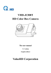
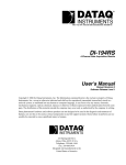
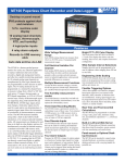
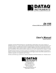
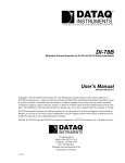
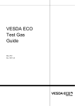
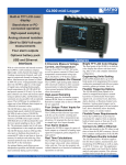
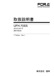
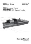
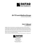
The way PC-based instrumentation should be
DI-725/E
Analog Channel Expander
User's Manual
Manual Revision E
Software Release Level 1
Copyright © 2009 by DATAQ Instruments, Inc. The Information contained herein is the exclusive property of
DATAQ Instruments, Inc., except as otherwise indicated and shall not be reproduced, transmitted, transcribed, stored
in a retrieval system, or translated into any human or computer language, in any form or by any means, electronic,
mechanical, magnetic, optical, chemical, manual, or otherwise without expressed written authorization from the company. The distribution of this material outside the company may occur only as authorized by the company in writing.
DATAQ Instruments’ hardware and software products are not designed to be used in the diagnosis and treatment of
humans, nor are they to be used as critical components in any life-support systems whose failure to perform can reasonably be expected to cause significant injury to humans.
241 Springside Drive
Akron, Ohio 44333 USA
www.dataq.com
Telephone: 330-668-1444
Fax: 330-666-5434
Designed and manufactured in the
United States of America
Warranty and Service Policy
Product Warranty
DATAQ Instruments, Inc. warrants that this hardware will be free from defects in materials and workmanship under
normal use and service for a period of one year from the date of shipment. DATAQ Instruments' obligations under
this warranty shall not arise until the defective material is shipped freight prepaid to DATAQ Instruments. The only
responsibility of DATAQ Instruments under this warranty is to repair or replace, at its discretion and on a free of
charge basis, the defective material.
This warranty does not extend to products that have been repaired or altered by persons other than DATAQ Instruments employees, or products that have been subjected to misuse, neglect, improper installation, or accident.
DATAQ Instruments shall have no liability for incidental or consequential damages of any kind arising out of the sale,
installation, or use of its products.
Service Policy
1.
All products returned to DATAQ Instruments for service, regardless of warranty status, must be on a freight-prepaid basis.
2.
DATAQ Instruments will repair or replace any defective product within 5 days of its receipt.
3.
For in-warranty repairs, DATAQ Instruments will return repaired items to the buyer freight prepaid. Out of warranty repairs will be returned with freight prepaid and added to the service invoice.
DI–725/E User Manual
Table of Contents
Warranty and Service Policy ................................................................................................................
Specifications ..........................................................................................................................................
Analog Inputs ....................................................................................................................................
Transfer Characteristics .....................................................................................................................
Amplifier Characteristics ...................................................................................................................
Dynamic Characteristics ....................................................................................................................
Stability ..............................................................................................................................................
Physical ..............................................................................................................................................
Environment ......................................................................................................................................
DI-725 General .......................................................................................................................................
Connecting the DI-725 to the Host Instrument .................................................................................
Features, Controls, and Indicators .....................................................................................................
DI-725 Front Panel ......................................................................................................................
DI-725 Rear Panel .......................................................................................................................
Configuring Channels with the DI-725 .............................................................................................
DI-400 Host Instruments .............................................................................................................
DI-720 Host Instruments .............................................................................................................
DI-730 Host Instruments .............................................................................................................
Table of Contents
v
iii
1
1
1
1
1
1
1
1
3
3
4
4
4
6
7
8
9
DI–725/E User Manual
Specifications
Analog Inputs
Number of channels
Input signal ranges
Gain (software selectable)
32 differential
1
2
4
8
Input Coupling
Maximum working voltage
(signal and common mode)
Overvoltage protection
Inputs protected
Measurement range (DI-725, DI-725E)
±10V, ±20V
±5V, ±10V
±2.5V, ±5V
±1.25V, ±2.5V
Each input should remain within ±10V of chassis ground
For the DI-725, ±30V powered on and off; For the DI-725E, ±120V powered
on and off
Channels 1-32
Transfer Characteristics
Nonlinearity
Offset error
Gain error
±0.01% FSR
±1mV ±5mV/gain
0.05% FSR
Amplifier Characteristics
Input impedance
Normal powered on
Overload or powered off
CMRR
CMRR input range
>1MΩ
1kΩ
80dB
±10V
Dynamic Characteristics
Settling time
Crosstalk
8ms (0.01%)
-72dB @ 100kHz & 100W unbalance
Stability
Recommended warm-up time
Offset temperature coefficient
15 minutes
(±2 ±50/gain)mV/°C
Physical
Dimensions
I/O Connectors
9 x 7.29 x 1.52 inches
37-pin male D, front; 40-pin ribbon cable, back
Environment
Operating temperature
Storage temperature
Relative humidity
0 to 50°C
-20 to 70°C
5% to 90% noncondensing
Specifications
1
DI–725/E User Manual
DI-725 General
The DI-725 is a 32-channel analog expansion device for DI-400, DI-720, and DI-730 instruments. The DI-725 features 32 differential analog inputs. The DI-725 is powered by the host DI-400, DI-720, or DI-730 instrument and in
most cases will not need an additional power supply. However, when several DI-725s are linked together, an additional power source may be required (indicated by a glowing POWER LOW lamp). The DI-725E requires an additional power source connected via the power input jacks located on the rear panel of the instrument.
Input signal ranges are as follows:
Gain
(Software Selectable)
1
2
4
8
Measurement Range
(DI-725*)
±10V
±5V
±2.5V
±1.25V
Measurement Range
(DI-725E**)
±20V
±10V
±5V
±2.5V
* For the DI-725, overvoltage protection is ±30V powered on and off.
** For the DI-725E, overvoltage protection is ±120V powered on and off.
In return for the 32 expansion channels it provides, each DI-725 consumes two channels from its host instrument.
When a single DI-725 is connected to a DI-400, the combination provides 46 total channels (14 channels are still
available on the host DI-400). When connected to a DI-720, the combination delivers 62 total channels (30 are still
available on the host DI-720). When connected to a DI-730, the DI-725 adds 32 high level differential inputs to the
host’s 8 wide measurement range inputs for a diverse blend of 40 total channels. A maximum of 240 channels may be
configured using multiple DI-725s.
Connecting the DI-725 to the Host Instrument
NOTE: The included expansion signal cable and dual-ended power cable are sized to fit when the DI-725 is stacked
on top of (or below) the host DI-720 or DI-730 instrument. If you are using these instruments and they are not in a
stacked configuration, do so before proceeding.
1.
Connect the appropriate end of the included expansion signal cable to the host instrument:
If you have this instrument:
DI-400
DI-720
DI-730
2.
Then connect the expansion cable to:
The DI-400’s 37-pin “D” connector
EXPANSION on the rear panel of the DI-720
EXPANSION on the rear panel of the DI-730
Connect the other end of the expansion cable to EXPANSION IN on the rear panel of the DI-725. Power for the
DI-725 is obtained from the host instrument through this cable. Power for the DI-725E must be supplied via the
power input jacks.
In General
3
DI–725/E User Manual
Features, Controls, and Indicators
DI-725 Front Panel
The two, 37-pin, male “D” connectors are used to connect your analog input signals to the DI-725. It can accept 32
high-level or preconditioned analog inputs in a differential configuration (one positive (+) and one negative (-) signal
lead per channel). High-level inputs are typically low impedance, no-conditioning-required signals in the range of
±1.25 to ±10 volts full scale.
DI-725 Rear Panel
POWER switch — Controls power to the DI-725 instrument. 1 is on, 0 is off.
POWER input jacks — Allows you to apply an alternate power source to the instrument, if necessary. The DI-725 is
powered by its host DI-400, DI-720, or DI-730 instrument and in most cases will not need an additional power supply. However, many factors can influence how much power is available to the DI-725 from its host instrument. When
the DI-725 cannot derive adequate power from its host instrument, the POWER LOW indicator will glow red. This
indicates that an alternate power source is necessary. Any suitable power source (+9 to +36 volts DC at 3A maximum) may be connected to either jack to provide the necessary power. When an alternate power source is connected,
the remaining jack can be used as an additional power outlet.
POWER status lamp — Glows green when the POWER switch is in the 1 position, indicating power is applied.
POWER LOW lamp — Glows red when the DI-725 cannot derive adequate power from its host instrument. In this
case, an alternate power source is required.
If the POWER LOW lamp comes on and you are using the DI-725 with a DI-720 or DI-730, the power supply that is
powering these host instruments can be used to power the DI-725 as well. Simply unplug the five-pin DIN end of the
power adapter cable that is currently supplying power to your DI-720 or DI-730, and plug it into one of the DI-725’s
power input jacks. Now plug one end of the supplied dual-ended power cable into the remaining power jack on the
DI-725 and plug the other end into the host instrument power input jack.
EXPANSION OUT connector — Used to connect multiple DI-725’s together. Connect one end of an expansion
cable to this connector and connect the other end of the cable to EXPANSION IN on the next DI-725.
EXPANSION IN connector — Connects the DI-725 to its host DI-400, DI-720, or DI-730 instrument.
In General
4
DI–725/E User Manual
In General
5
DI–725/E User Manual
Configuring Channels with the DI-725
In WINDAQ/Pro or WINDAQ/Pro+ data acquisition software, channels are enabled or configured for acquisition with
the channel selection grid. The channel selection grid is accessed by selecting Channels… from the Edit menu (in the
SET-UP operating mode of WINDAQ software).
Each box in this grid potentially represents an input channel. An input channel is enabled by clicking the desired box.
Which box you click, which mouse button you click with, and how many times you click the mouse button determines whether the input channel is enabled for single-ended operation, differential operation, or digital input operation.
The following pages show how to enable channels when using the DI-725 with a DI-400, DI-720, and DI-730 host
instrument.
In General
6
DI–725/E User Manual
DI-400 Host Instruments
The following channel selection grid is typical when a single DI-725 is used with a DI-400. Note that the DI-400
channels are enabled on the top row of the grid and the DI-725 channels are enabled on the row labeled “MUX A”.
The shaded area on the top row shows the channels that are still available on the host DI-400 instrument when the DI725 is added.
When a Single DI-725 is Used.
AA
These 14
channels are
still available on
the host DI-400.
These 2 channels are consumed by
the DI-725 (therefore unavailable).
These are the
32 DI-725
expansion
channels
(enable them
on this row).
The following grid is typical of two DI-725’s used with a DI-400. Note the pattern. Each DI-725 consumes the two
highest-numbered channels on the host DI-400, and the expansion channels are enabled on the next MUX row down.
The result is similar when more DI-725’s are added to the system.
When Two DI-725’s are Used.
BB AA
These 12
channels are
still available on
the host DI-400.
These are the
32 expansion
channels on
the first DI725 (the one
directly
connected to
the DI-400).
Enable them
on this row).
These 4 channels are consumed by
the DI-725’s (therefore unavailable).
These are the next 32 expansion
channels on the second DI-725 (the
one not directly connected to the DI400). Enable them on this row.
In General
7
DI–725/E User Manual
DI-720 Host Instruments
The following channel selection grid is typical when a single DI-725 is used with a DI-720. Note that the DI-720
channels are enabled on the top row of the grid and the DI-725 channels are enabled on the row labeled “MUX A”.
The shaded area on the top row shows the channels that are still available on the host DI-720 instrument when the DI725 is added.
When a Single DI-725 is Used.
AA
These 30
channels are
still available on
the host DI-720.
These 2 channels are
consumed by the DI-725
(therefore unavailable).
These are the
32 DI-725
expansion
channels
(enable them
on this row).
The following grid is typical of two DI-725’s used with a DI-720. Note the pattern. Each DI-725 consumes the two
highest-numbered channels on the host DI-720, and the expansion channels are enabled on the next MUX row down.
The result is similar when more DI-725’s are added to the system.
When Two DI-725’s are Used.
BB AA
These 28
channels are
still available on
the host DI-720.
These are the
32 expansion
channels on the
first DI-725
(the one directly
connected to
the DI-720).
Enable them on
this row).
These 4 channels are consumed by
the DI-725’s (therefore unavailable).
These are the next 32 expansion
channels on the second DI-725 (the
one not directly connected to the DI720). Enable them on this row.
In General
8
DI–725/E User Manual
DI-730 Host Instruments
The following channel selection grid is typical when a single DI-725 is used with a DI-730. Note that the DI-730
channels are enabled on the top row of the grid and the DI-725 channels are enabled on the row labeled “MUX A”.
The shaded area on the top row of the grid shows the channels that are still available on the host DI-730 instrument
when the DI-725 is added.
When a Single DI-725 is Used.
AA
These 8
channels are
still available on
the host DI-730.
These 2 channels are
consumed by the DI-725.
These are the
32 DI-725
expansion
channels
(enable them
on this row).
The following grid is typical of two DI-725’ s used with a DI-730. Note the pattern. Each DI-725 consumes the two
highest-numbered channels on the host DI-730, and the expansion channels are enabled on the next MUX row down.
The result is similar when more DI-725’s are added to the system.
When Two DI-725’s are Used.
BBAA
These 8
channels are
still available on
the host DI-730.
These are the
32 expansion
channels on the
first DI-725
(the one directly
connected to
the DI-730).
Enable them on
this row.
These 4 channels are consumed by
the DI-725’s.
These are the next 32 expansion
channels on the second DI-725 (the
one not directly connected to the DI730). Enable them on this row.
In General
9
DATAQ Instruments, Inc.
241 Springside Drive
Akron, Ohio 44333
Telephone: 330-668-1444
Fax: 330-666-5434
E-mail: [email protected]
Direct Product Links
(click on text to jump to page)
Data Acquisition | Data Logger | Chart Recorder | Thermocouple | Oscilloscope