1
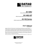
PRESSURE | LOAD | TORQUE | POSITION | ROTARY ANGLE | TILT | ACCELERATION | VIBRATION | RATE | SIGNAL CONDITIONER | DATALOGGER The way PC-based instrumentation should be DI-149 8-Channel USB Data Acquisition Starter Kit User's Manual Manual Revision I Copyright © 2012 by DATAQ Instruments, Inc. The Information contained herein is the exclusive property of DATAQ Instruments, Inc., except as otherwise indicated and shall not be reproduced, transmitted, transcribed, stored in a retrieval system, or translated into any human or computer language, in any form or by any means, electronic, mechanical, magnetic, optical, chemical, manual, or otherwise without expressed written authorization from the company. The distribution of this material outside the company may occur only as authorized by the company in writing. DATAQ Instruments' hardware and software products are not designed to be used in the diagnosis and treatment of humans, nor are they to be used as critical components in any life-support systems whose failure to perform can reasonably be expected to cause significant injury to humans. DATAQ, the DATAQ logo, and WINDAQ are registered trademarks of DATAQ Instruments, Inc. All rights reserved. DATAQ Instruments, Inc. 241 Springside Drive Akron, Ohio 44333 U.S.A. Telephone: 330-668-1444 Fax: 330-666-5434 Designed and manufactured in the United States of America ACCURATE. FlexibLE. SOPHISTICATED. SINCE 1978. ALTHEN GmbH • Frankfurter Str. 150-152 • 65779 Kelkheim • Telefon +49 (0)6195 / 70060 • [email protected] • www.althen.de Warranty and Service Policy Product Warranty DATAQ Instruments, Inc. warrants that this hardware will be free from defects in materials and workmanship under normal use and service for a period of 90 days from the date of shipment. DATAQ Instruments' obligations under this warranty shall not arise until the defective material is shipped freight prepaid to DATAQ Instruments. The only responsibility of DATAQ Instruments under this warranty is to repair or replace, at its discretion and on a free of charge basis, the defective material. This warranty does not extend to products that have been repaired or altered by persons other than DATAQ Instruments employees, or products that have been subjected to misuse, neglect, improper installation, or accident. DATAQ Instruments shall have no liability for incidental or consequential damages of any kind arising out of the sale, installation, or use of its products. Service Policy 1. All products returned to DATAQ Instruments for service, regardless of warranty status, must be on a freight-prepaid basis. 2. DATAQ Instruments will repair or replace any defective product within 5 days of its receipt. 3. For in-warranty repairs, DATAQ Instruments will return repaired items to the buyer freight prepaid. Out of warranty repairs will be returned with freight prepaid and added to the service invoice. iii ALTHEN GmbH • Frankfurter Str. 150-152 • 65779 Kelkheim • Telefon +49 (0)6195 / 70060 • [email protected] • www.althen.de ALTHEN GmbH • Frankfurter Str. 150-152 • 65779 Kelkheim • Telefon +49 (0)6195 / 70060 • [email protected] • www.althen.de DI-149 Hardware Manual Table of Contents Warranty and Service Policy ................................................................................................................ 1. Introduction ........................................................................................................................................ Features .............................................................................................................................................. Analog Inputs .................................................................................................................................... Digital Inputs ..................................................................................................................................... Digital Outputs .................................................................................................................................. Software ............................................................................................................................................. WINDAQ® Recording and Playback Software ........................................................................... The DATAQ Instruments Hardware Manager ............................................................................ Help ............................................................................................................................................. 2. Specifications ...................................................................................................................................... 3. Installation .......................................................................................................................................... Installing WINDAQ Software and the DATAQ Instruments Hardware Manager ............................. Connecting the Instrument to Your Computer .................................................................................. DATAQ Instruments Hardware Manager ......................................................................................... 4. Controls, Indicators, and Connections ............................................................................................. Mini-B USB Connection ................................................................................................................... Connecting Input Signals ................................................................................................................... DI-149 Signal Connections ......................................................................................................... Connect Analog Input Channel 1 ................................................................................................ Connecting Signal Leads ............................................................................................................ Digital Inputs ............................................................................................................................... WINDAQ Remote Events (Evnt/DI0) .................................................................................... WINDAQ Remote Storage (Rcrd/DI1) .................................................................................. WINDAQ Rate (Rate/DI2) ..................................................................................................... WINDAQ Counter/Timer (Cnt/DI3) ...................................................................................... General Purpose Digital Inputs ............................................................................................ 4-20mA Current Loop Measurements ............................................................................................... LED Indicators .................................................................................................................................. 5. DI-149 Block Diagram ....................................................................................................................... 6. Dimensional Drawing ......................................................................................................................... iii 1 1 1 1 1 1 2 2 2 3 5 5 6 6 7 7 7 7 8 8 9 10 11 12 14 15 16 17 19 21 Table of Contents v ALTHEN GmbH • Frankfurter Str. 150-152 • 65779 Kelkheim • Telefon +49 (0)6195 / 70060 • [email protected] • www.althen.de ALTHEN GmbH • Frankfurter Str. 150-152 • 65779 Kelkheim • Telefon +49 (0)6195 / 70060 • [email protected] • www.althen.de DI-149 Hardware Manual 1. Introduction This manual contains information designed to familiarize you with the features and functions of the DI-149 USB data acquisition starter kit. These high-end Starter kits contain features and functionality normally reserved for more expensive data acquisition systems. Features The DI-149 data acquisition instrument is a portable data recording module that communicates through your computer's USB port. Power is derived from the interface port so no external power is required. Features include: • 8 fixed differential analog inputs protected to ±150V (transient). • 4 digital inputs protected to ±30V: Two dedicated for WINDAQ remote control operations; One dedicated to WINDAQ rate measurements; and One dedicated to WINDAQ counter measurements. • ±10V full scale measurement range. • Up to 10 kHz (11 kHz for 11 enabled channels (8 analog, 3 digital) maximum sampling rate (requires WINDAQ/ High Speed option). • A push-button to tag remote events in WINDAQ software. • Four dedicated digital output ports for use via a programming language or with 3rd party plug-ins. • Three status LEDs for easy notification of system status. Analog Inputs The DI-149 features eight differential channel inputs located on two sixteen-position screw terminal blocks for easy connection and operation (other terminals used for digital I/O). Note: The DI-149 does not support Gain. Utilize the functionality of WINDAQ software to experience all the features encased in these small, inexpensive instruments. Digital Inputs The DI-149 contains four digital lines (bits) for WINDAQ remote control operations (Remote Start/Stop and Remote Events), frequency measurements, and counts. Connect switch closures or discrete levels with a maximum input of 30V and a threshold of 1.8V. The inputs float at 1 level, about 3.3V relative to the “-” terminal, and require sinking about 50uA to bring them down to 0.8V and guarantee a 0. Digital Outputs The DI-149 contains four general purpose digital output lines (30 VDC or peak AC, 500 mA max) for use with third party applications or from a programming language. WINDAQ does not support these digital outputs. Software All software required to record and playback waveforms is included with the purchase of any DI-149 data acquisition starter kit via download. Introduction 1 ALTHEN GmbH • Frankfurter Str. 150-152 • 65779 Kelkheim • Telefon +49 (0)6195 / 70060 • [email protected] • www.althen.de DI-149 Hardware Manual WINDAQ® Recording and Playback Software WINDAQ Acquisition and WINDAQ Waveform Browser allow you to record and playback data acquired through your instrument. WINDAQ software is an invaluable resource to record and analyze your data and is available for free from our web site (www.dataq.com). WINDAQ/Lite Data Acquisition software (free) can be used to record waveforms directly and continuously to disk while monitoring a real time display of the waveforms on-screen. It operates, displays, and records waveform signals in real time at 240Hz maximum throughput. WINDAQ/High Speed Data Acquisition software (extra-cost option) unlocks the sample rate restriction allowing you to record data at the maximum throughput rate of the instrument (10kHz for the DI-149). WINDAQ Waveform Browser playback software (also known as “WWB”) offers an easy way to review and analyze acquired waveforms. A built-in data file translator allows the user to display multiple waveforms acquired by WINDAQ Acquisition software or any of a wide range of data acquisition packages. The software’s disk-streaming design allows data files of any length to be graphically displayed rapidly, in normal or reverse time directions. Seven standard cursor-based measurements, frequency domain, and statistical analysis functions help simplify waveform analysis and interpretation. WINDAQ Waveform Browser is free and installed when installing WINDAQ Software. The DATAQ Instruments Hardware Manager This software can be found in the Start menu under the WINDAQ program group called DATAQ Instruments Hardware Manager. Access WINDAQ Acquisition software and manage multiple DATAQ Instruments devices in this easy-to-use point and click environment. View the Help files by clicking on View Help in the Help menu or by pressing F1. Help All WINDAQ software utilizes context-sensitive help. Help may be accessed through the Help menu or by pressing the F1 key with any pull-down menu item selected. This will take you directly to the Help topic most relevant to that particular function or feature. Help topics discuss in detail each function available in the software. Introduction 2 ALTHEN GmbH • Frankfurter Str. 150-152 • 65779 Kelkheim • Telefon +49 (0)6195 / 70060 • [email protected] • www.althen.de DI-149 Hardware Manual 2. Specifications Analog Inputs Number of Channels: 8 Channel Configuration: Differential Voltage Measurement Range: ±10V Full Scale Input impedance: 2 M, differential Isolation: none Overall inaccuracy: ±64mV (at 25°C) Minimum common mode rejection: 40db @ 50-60 Hz and @ 25°C Max input without damage: ±75 V peak continuous; ±150 V peak, one minute or less Max common mode voltage: ±10V Analog frequency response: -3db @ 1,000 Hz Digital Inputs Number of Channels: 4 (2 shared with counter/rate inputs) Pull-up value: 47 K from + input to 3.3V Isolation: none Input high voltage threshold: 1.8 V minimum Input low voltage threshold: 1.4 V maximum Absolute maximum values: ±30 VDC Reserved Inputs (Digital Inputs) Digital In 0: WINDAQ remote events Digital In 1: WINDAQ remote start/stop Counter/Rate (DI2 and DI3) Number of Channels: 2 (shared with digital inputs) Port Assignment: Rate = DI2; Counter = DI3 Pull-up value: 47 K Isolation: none Input high voltage threshold: 1.8 V minimum Input low voltage threshold: 1.4 V maximum Absolute maximum values: ±30 VDC Terminal count: 16,384 (14-bit) Maximum Rate Frequency: The lesser of 10 kHz or 2 × burst rate per channel Minimum Rate Frequency: 0.50 Hz Maximum Count Frequency: The lesser of 5 kHz or 0.50 × burst rate per channel (assumes 50% duty cycle square wave) Rate averaging: none Specifications 3 ALTHEN GmbH • Frankfurter Str. 150-152 • 65779 Kelkheim • Telefon +49 (0)6195 / 70060 • [email protected] • www.althen.de DI-149 Hardware Manual ADC Characteristics Resolution: Overall: approx. 1 part in 1,024 (10-bit) Above zero: approx. 1 part in 511 Below zero: approx. 1 part in 512 Max. sample throughput rate: 10,000 Hz - 11,000 Hz for 11 enabled channels (8 analog, 3 digital) Min. sample throughput rate: 11.44 Hz (0.000350 Hz with WinDaq software) Sample rate timing accuracy: 50 ppm Digital Outputs Number of Channels: 4 Isolation: none Absolute max ratings: Voltage: 30 VDC or peak AC Sink current: 0.5 A Source current: 3 mA On resistance < 2 Indicators and Connections Interface: USB 2.0 (mini-B style connector) Indicators (LED): Power, Active, Digital Input Connections: Two 16-position terminal strip Power Power Consumption: <1.0 Watt, via USB interface Environmental Operating Temperature: 0°C to 35°C (32°F to 95°F) Operating Humidity: 0 to 90% non-condensing Storage Temperature: -20°C to 45°C (-4°F to 113°F) Storage Humidity: 0 to 90% non-condensing Physical Characteristics Enclosure: Hardened Plastic Mounting: Desktop; bulkhead Dimensions: 2.625D × 5.5W × 1.53H in. (6.67D × 13.97W × 3.89H cm.) Weight: < 4 oz. (< 140 grams) Software Support WINDAQ/Lite software (free): OS support: Windows XP (32-bit), Windows Vista and Windows 7 (32and 64-bit versions) Sample Rate Limit: 240 Hz WinDaq/HS software (optional): OS support: Same as WinDaq/Lite Sample Rate Limit: 10,000 Hz Programming: DATAQ SDK, Instrument Protocol, DLL, and Active X Specifications 4 ALTHEN GmbH • Frankfurter Str. 150-152 • 65779 Kelkheim • Telefon +49 (0)6195 / 70060 • [email protected] • www.althen.de DI-149 Hardware Manual 3. Installation The following items are included with each WINDAQ Starter Kit. Verify that you have the following: • A DI-149 USB data acquisition instrument. • USB cable. • A DATAQ Instruments screwdriver for signal lead connections. If an item is missing or damaged, call DATAQ Instruments at 330-668-1444. We will guide you through the appropriate steps for replacing missing or damaged items. Save the original packing material in the unlikely event that your unit must, for any reason, be sent back to DATAQ Instruments. Installing WINDAQ Software and the DATAQ Instruments Hardware Manager All software for the DI-149 can be installed via a downloadable executable directly from the DATAQ Instruments web site. No CD is shipped with the device. You may burn the executable onto a CD to transport the software to a computer with no internet connection. 1. Disconnect all DATAQ Instruments USB devices from your Computer. 2. Go to www.dataq.com/149 in your web browser. 3. Click on the Download Now 4. Save the file to your local hard drive. button. Installation 5 ALTHEN GmbH • Frankfurter Str. 150-152 • 65779 Kelkheim • Telefon +49 (0)6195 / 70060 • [email protected] • www.althen.de DI-149 Hardware Manual 5. Double-click on the downloaded file (dataq_149_install.exe) to extract the program and begin software installation. 6. Follow the on-screen prompts and enter any required information. 7. Software installation is complete - you will now see a “Successful Installation” box - click OK to exit WINDAQ Installation. You can now plug the device(s) into your PC. Click on the appropriate program group (specified above — default is Start > Programs > WINDAQ) and click on “DATAQ Instruments Hardware Manager” to access WINDAQ software. Connecting the Instrument to Your Computer DI-149 instruments can be connected to your computer’s USB port using the provided USB cable. No external power is required. Connect one end of the communications cable to the instrument port and the other to your PC’s port. Note: Use a powered USB hub or a USB port on your PC. Non-powered USB hubs may not have sufficient power to run the instrument. DATAQ Instruments Hardware Manager The DATAQ Instruments Hardware Manager is installed when installing any DI-149 instrument. This software allows you to effectively manage multiple devices installed on the same PC. The DATAQ Instruments Hardware Manager may be accessed through the Windows Program Manager Group as specified during installation (default is Start > Programs > WINDAQ > DATAQ Instruments Hardware Manager). All available devices will automatically appear in the list box when you run the software. The Hardware Manager allows you to start WINDAQ Acquisition software (select the device and click on the Start Windaq button) and must be used when multiple DATAQ Instruments devices are installed. It also provides crucial information about your device needed for custom programming (Serial # and COM Port). Please note: The description of DI-149 models cannot be modified. Click on the Help button for help with the DATAQ Instruments Hardware Manager. Installation 6 ALTHEN GmbH • Frankfurter Str. 150-152 • 65779 Kelkheim • Telefon +49 (0)6195 / 70060 • [email protected] • www.althen.de DI-149 Hardware Manual 4. Controls, Indicators, and Connections Analog In Channels 5-8 - + + Event Marker Push Button - + Digital Out Channels - + - + Ch7 Ch8 Ch5 Ch6 Analog Inputs (±10 VFS, ±150 V max) - + - + SD Card Slot (not used in DI-149) - Model DI-149 Power Power, Active, and Remote LEDs - + DO0 DO1 DO2 DO3 Digital Outputs (30 VDC max.) Download software at dataq.com/149 Active www.dataq.com Remote Data Acquisition Starter Kit Analog Inputs (±10 VFS, ±150 V max) Digital Inputs (±30 V max.) Ch1 Ch2 Ch3 Ch4 Evnt/DI0 Rcrd/DI1 Rate/DI2 Cnt/DI3 Bulkhead Mounting Ear - + + - + - + - + - - + + - + - Bulkhead Mounting Ear Mini-B USB Connection Analog In Channels 1-4 Digital In Channels Please note: The SD card slot is not used in the DI-149. Allowing foreign materials to enter the device through the SD card slot may result in damage to the instrument. Mini-B USB Connection Use the supplied USB cable to connect and power the instrument through your computer’s USB port. Connecting Input Signals All input signal connections are made to the 16-port screw terminals. Each terminal is labeled directly on the instrument case. DI-149 Signal Connections Refer to the following for screw terminal port identification. + - + - + - + - Ch7 Ch8 Ch5 Ch6 Analog Inputs (±10 VFS, ±150 V max) + - + - + - + - DO0 DO1 DO2 DO3 Digital Outputs (30 VDC max.) Model DI-149 Power Download software at dataq.com/149 Active www.dataq.com Remote Data Acquisition Starter Kit Analog Inputs (±10 VFS, ±150 V max) Digital Inputs (±30 V max.) Evnt/DI0 Rcrd/DI1 Rate/DI2 Cnt/DI3 Ch1 Ch2 Ch3 Ch4 + - + - + - + - + - + - + - + - Analog Inputs Ch#: Analog channels 1-8 (±10VFS, ±150V transient max.) Controls, Indicators, and Connections 7 ALTHEN GmbH • Frankfurter Str. 150-152 • 65779 Kelkheim • Telefon +49 (0)6195 / 70060 • [email protected] • www.althen.de DI-149 Hardware Manual Digital Inputs: General purpose digital inputs (bits 0-3). Can also be used for specific WINDAQ functions (± 30 Vmax). Digital Input bit 0 (Evnt/DI0)—WINDAQ Remote Event Marker Digital Input bit 1(Rcrd/DI1)—WINDAQ Remote Start/Stop Digital Input bit 2 (Rate/DI2)—WINDAQ Rate Input Digital Input bit 3 (Cnt/DI3)—WINDAQ Counter Input Digital Outputs DO#: General purpose digital outputs (bits 0-3) for use in 3rd party programs (30 VDC max). Connect Analog Input Channel 1 Use the following diagram to connect Analog Input Channel 1. + - + - + - + - + Ch7 Ch8 Ch5 Ch6 Analog Inputs (±10 VFS, ±150 V max) - + - + - + - DO0 DO1 DO2 DO3 Digital Outputs (30 VDC max.) Model DI-149 Power Download software at dataq.com/149 Active www.dataq.com Remote Data Acquisition Starter Kit Analog Inputs (±10 VFS, ±150 V max) Digital Inputs (±30 V max.) Ch1 Ch2 Ch3 Ch4 Evnt/DI0 Rcrd/DI1 Rate/DI2 Cnt/DI3 + Signal + - + - + - + - + - + - + - + - Signal - Connecting Signal Leads To connect signal leads to the DI-149: 1. Insert the stripped end of a signal lead into the desired terminal directly under the screw. 2. Tighten the pressure flap by rotating the screw clockwise with a small screwdriver. Make sure that the pressure flap tightens only against the signal wire and not the wire insulation. Do not over-tighten. Controls, Indicators, and Connections 8 ALTHEN GmbH • Frankfurter Str. 150-152 • 65779 Kelkheim • Telefon +49 (0)6195 / 70060 • [email protected] • www.althen.de DI-149 Hardware Manual 3. Tug gently on the signal lead to ensure that it is firmly secured. When an input signal is connected and WINDAQ Acquisition software is run, WINDAQ’s real time display immediately reveals the input waveform on your computer’s monitor. Digital Inputs The DI-149 contains 4 general purpose digital inputs that can also be used for specific WINDAQ functions: Evnt/DI0 is for WINDAQ Remote Events. This bit inserts an event marker in your data. Rcrd/DI1 is for WINDAQ Remote Storage. This bit can be programmed to begin recording data. Rate/DI2 is for WINDAQ Rate measurements. Cnt/DI3 is for WINDAQ Counter/Timer measurements. Valid remote record and event signals are switch closures or discrete levels with a maximum input of 30 V and a threshold of 1.8 V. TTL Switch Closure 30V Max 1.8V Threshold 0V Controls, Indicators, and Connections 9 ALTHEN GmbH • Frankfurter Str. 150-152 • 65779 Kelkheim • Telefon +49 (0)6195 / 70060 • [email protected] • www.althen.de DI-149 Hardware Manual WINDAQ Remote Events (Evnt/DI0) To use a switch closure or TTL signal to record WINDAQ Event Markers, connect signal leads to the appropriate Remote Control Event terminals on the DI-149 as shown below. + - + - + - + - + Ch7 Ch8 Ch5 Ch6 Analog Inputs (±10 VFS, ±150 V max) - + - + - - + DO0 DO1 DO2 DO3 Digital Outputs (30 VDC max.) Model DI-149 Power Download software at dataq.com/149 Active www.dataq.com Remote Data Acquisition Starter Kit Analog Inputs (±10 VFS, ±150 V max) Digital Inputs (±30 V max.) Ch1 Ch2 Ch3 Ch4 Evnt/DI0 Rcrd/DI1 Rate/DI2 Cnt/DI3 + - + - + - + - + - + Signal + - + - + - Signal - Once the switch closure or TTL signal is connected, activate Remote Events through WINDAQ Acquisition Software. Events may be automatically placed on the rising or falling edge of the trigger signal. Use the menu command Options > Remote Events + to set WINDAQ to place event markers on low-to-high transitions of the Event input. Use the menu command Options > Remote Events - to set WINDAQ to place event markers on high-to-low transitions of the Event input. Event markers may also be placed in your data file manually by pressing the push button on the DI-149 Instrument. You must enable Remote Events in WINDAQ to use the button (use the menu command Options > Remote Events +or Options > Remote Events -). + - + - + - + - Ch7 Ch8 Ch5 Ch6 Analog Inputs (±10 VFS, ±150 V max) + - + - + - + - DO0 DO1 DO2 DO3 Digital Outputs (30 VDC max.) Model DI-149 Power Download software at dataq.com/149 Active www.dataq.com Remote Data Acquisition Starter Kit Analog Inputs (±10 VFS, ±150 V max) Digital Inputs (±30 V max.) Evnt/DI0 Rcrd/DI1 Rate/DI2 Cnt/DI3 Ch1 Ch2 Ch3 Ch4 + - + - + - + - + - + - + - + - Controls, Indicators, and Connections 10 ALTHEN GmbH • Frankfurter Str. 150-152 • 65779 Kelkheim • Telefon +49 (0)6195 / 70060 • [email protected] • www.althen.de DI-149 Hardware Manual An example event marker in a WINDAQ data file is shown below. *Please Note: Event Markers do not display in the real-time WINDAQ acquisition software - they only display in the WINDAQ playback software (WWB). WINDAQ Remote Storage (Rcrd/DI1) To use a switch closure or TTL signal to begin recording data remotely, connect signal leads to the appropriate Remote Control Record terminals on the DI-149 as shown below. Once the switch closure or TTL signal is connected, activate Remote Storage (Record) through WINDAQ Acquisition Software. Storage to Disk may be automatically placed on the rising or falling edge of the trigger signal. Use the menu command Options > Remote Storage 1 to set WINDAQ to begin recording on low-to-high transitions of the Controls, Indicators, and Connections 11 ALTHEN GmbH • Frankfurter Str. 150-152 • 65779 Kelkheim • Telefon +49 (0)6195 / 70060 • [email protected] • www.althen.de DI-149 Hardware Manual Record input. Use the menu command Options > Remote Storage 0 to set WINDAQ to begin recording on high-tolow transitions of the Record input. + - + - + - + - + Ch7 Ch8 Ch5 Ch6 Analog Inputs (±10 VFS, ±150 V max) - + - + - + - DO0 DO1 DO2 DO3 Digital Outputs (30 VDC max.) Model DI-149 Power Download software at dataq.com/149 Active www.dataq.com Remote Data Acquisition Starter Kit Analog Inputs (±10 VFS, ±150 V max) Digital Inputs (±30 V max.) Evnt/DI0 Rcrd/DI1 Rate/DI2 Cnt/DI3 Ch1 Ch2 Ch3 Ch4 + - + - + - + - + Signal + - + - + - + - Signal - WINDAQ Rate (Rate/DI2) Enable channel 10 to record Rate, or the number of falling-edge transitions per unit of time that are applied to this input. Click on Edit > Channels in the WINDAQ Acquisition menu to open the Channel Selection grid. Channel 10 is the designated Rate channel. Click on the Channel 10 channel box to enable/disable Rates. The Channel 10 channel box will display an “R” when enabled. Controls, Indicators, and Connections 12 ALTHEN GmbH • Frankfurter Str. 150-152 • 65779 Kelkheim • Telefon +49 (0)6195 / 70060 • [email protected] • www.althen.de DI-149 Hardware Manual Connect any TTL pulse stream (30 VDC max) to the Rate/DI2 channel on the DI-149. + - + - + - + - + Ch7 Ch8 Ch5 Ch6 Analog Inputs (±10 VFS, ±150 V max) - + - + - + - DO0 DO1 DO2 DO3 Digital Outputs (30 VDC max.) Model DI-149 Power Download software at dataq.com/149 Active www.dataq.com Remote Data Acquisition Starter Kit Analog Inputs (±10 VFS, ±150 V max) Digital Inputs (±30 V max.) Ch1 Ch2 Ch3 Ch4 Evnt/DI0 Rcrd/DI1 Rate/DI2 Cnt/DI3 + - + - + - + - + - + Signal + - + - + - Signal - Select Channel 10 in the channel display, then select Edit > Channel Settings in the menu to specify a full scale range for the Rate channel. Ranges of 5, 10, 20, 50, 100, 200, 500, 1000, 2000, 5000, and 10000 Hz are available. Choose a range that comes closest to your expected full scale rate or frequency. For example, if you need to measure the output of a flow meter that can measure a maximum flow rate of 100 gallons per minute, and the output frequency at that rate is 100 Hz, you would choose the 100 Hz range setting. A range setting of 200 Hz full scale sacrifices half of the instrument's resolution at 200 gallons per minute, and a range of 50 Hz allows measurements to only 50 gallons per minute full scale. Controls, Indicators, and Connections 13 ALTHEN GmbH • Frankfurter Str. 150-152 • 65779 Kelkheim • Telefon +49 (0)6195 / 70060 • [email protected] • www.althen.de DI-149 Hardware Manual Check the "Cycles/min" box to display and select frequencies reported in cycles per minute instead of cycles per second (the measurement interval remains the same). Tachometer measurements in units of RPM (revolutions per minute) is just one example that benefits from selecting this option. For example, if the 100 Hz range setting is selected and "Cycles/min" is checked, the full scale range is actually 6000 cycles per minute. Please Note: To measure the maximum rate, which is defined as 2 times the Maximum Sample Rate/Channel , the current values of Maximum Sample Rate/Channel divided by Sample Rate per Channel MUST be an integer. WINDAQ Counter (Cnt/DI3) Enable channel 11 to record Counts, or the number of falling-edge transitions that are applied to this input. The count may be reset via WINDAQ software or under program control as necessary. Click on Edit > Channels in the WINDAQ Acquisition menu to open the Channel Selection grid. Channel 11 is the designated Count channel. Click on the Channel 11 channel box to enable/disable Counts. The Channel 11 channel box will display a “C” when enabled. The counter channel accumulates counts over time whether recording or in standby mode as soon as the Counter channel is enabled. The accumulated values will be recorded to your data file unless you reset the counts to zero. The maximum count value is 16383 before the counter resets to zero automatically. Use the Edit > Reset Count command in WINDAQ Acquisition software to reset counts immediately to zero. This feature is available in both standby and record modes. Use the Edit > Preferences > Reset Count on New File Record in WINDAQ Acquisition software to reset the count at the start of a new file or when using the Edit > Preferences > Record Next File on Full or Open Next File on Full feature to reset counts to zero every time a new file is started. Use the Edit > Preferences > Reset Count on Manual Record in WINDAQ Acquisition software to reset counts to zero every time you begin or resume recording a data file using the File > Record command (F4). Controls, Indicators, and Connections 14 ALTHEN GmbH • Frankfurter Str. 150-152 • 65779 Kelkheim • Telefon +49 (0)6195 / 70060 • [email protected] • www.althen.de DI-149 Hardware Manual Connect any TTL pulse stream (30 VDC max) to the Cnt/DI3 channel on the DI-149. - + + - + - + - + Ch7 Ch8 Ch5 Ch6 Analog Inputs (±10 VFS, ±150 V max) - + - + - + - DO0 DO1 DO2 DO3 Digital Outputs (30 VDC max.) Model DI-149 Power Download software at dataq.com/149 Active www.dataq.com Remote Data Acquisition Starter Kit Analog Inputs (±10 VFS, ±150 V max) Digital Inputs (±30 V max.) Ch1 Ch2 Ch3 Ch4 Evnt/DI0 Rcrd/DI1 Rate/DI2 Cnt/DI3 - + + - + - + - + - + - + - + - Signal + Signal - General Purpose Digital Inputs Enable Channel 9 for general purpose digital input functions. Click on Edit > Channels in the WINDAQ Acquisition menu to open the Channel Selection grid. Channel 9 is the designated Digital Input channel. Click on the Channel 9 channel box to enable/disable the digital inputs. The Channel 9 channel box will display an “I” when enabled. Controls, Indicators, and Connections 15 ALTHEN GmbH • Frankfurter Str. 150-152 • 65779 Kelkheim • Telefon +49 (0)6195 / 70060 • [email protected] • www.althen.de DI-149 Hardware Manual Channel 9 records and displays all the digital inputs, even the state of the Rate and Count inputs if those channels are enabled. With Channel 9 selected in the display window click Scaling > Digital Plot to show a digital display and make the data more meaningful on screen. 4-20mA Current Loop Measurements Use the following diagram for 4-20mA current loop measurement connections. + + + - - + + + - - - - + + - - + - - + + - - Download software at dataq.com/149 + DO0 DO1 DO2 DO3 Digital Outputs (30 VDC max.) + + Model DI-149 + www.dataq.com - Ch5 Ch6 Ch7 Ch8 Analog Inputs (±10 VFS, ±150 V max) + - - Power Active Remote Data Acquisition Starter Kit Analog Inputs (±10 VFS, ±150 V max) Digital Inputs (±30 V max.) Evnt/DI0 Rcrd/DI1 Rate/DI2 Cnt/DI3 Ch1 Ch2 Ch3 Ch4 Shunt Resistor Model R250 + 4-20 mA current source The shunt resistor should be placed on the low side of the circuit as shown below: Current Loop Transmitter I 4-20mA Loop Power Supply ���� Shunt Resistor + - To DI-149 Analog Input Channel Controls, Indicators, and Connections 16 ALTHEN GmbH • Frankfurter Str. 150-152 • 65779 Kelkheim • Telefon +49 (0)6195 / 70060 • [email protected] • www.althen.de DI-149 Hardware Manual Set the engineering units as desired and define low/high calibration values in WINDAQ as 1V = 4mA for the low value and 5V = 20mA for the high value. For example, when using WINDAQ Acquisition software, in the Channel 1 Low Calibration dialog box: Enter the following values: Input Level = 1 Low Cal Value 4 Engr. Units = mA In the High Calibration dialog box: Enter the following values (the Low Cal values are displayed): Calibrator Input Level Input Units Calibrator Value Engr. Units Low 1 Volt 4 mA High 5 Volt 20 mA You can also associate these values to a physical measurement such as pressure, load, flow, torque, etc. Read the Help files for more information regarding Waveform Calibration. LED Indicators The DI-149 provides three green LEDs for instrument status and notification. Controls, Indicators, and Connections 17 ALTHEN GmbH • Frankfurter Str. 150-152 • 65779 Kelkheim • Telefon +49 (0)6195 / 70060 • [email protected] • www.althen.de DI-149 Hardware Manual Power: Indicates power is applied via the USB cable. Active: Indicates the device is in use either by WINDAQ Acquisition Software or a custom user-developed program. Remote: Indicates when the Event Button is pushed or the Event terminals are connected via a relay contact or digital input. Controls, Indicators, and Connections 18 ALTHEN GmbH • Frankfurter Str. 150-152 • 65779 Kelkheim • Telefon +49 (0)6195 / 70060 • [email protected] • www.althen.de DI-149 Hardware Manual 5. DI-149 Block Diagram VBus Digital Outputs Typical 4 places 0.001�� Absolute Maximum Ratings VDO0 to Common: 30 V ILoad (sink): 0.5 A ILoad (source): 0.3 mA 160K 10K DOUT0 Load * 1M 10 AIN1 1M Common 0.1�� 0.001�� 160K Analog In Typical 8 places ILoad 4.7K ½���� ������������������������ Loads such as a relay 10 EEPROM (Calibration, Model #, Serial #) +V Event General Purpose I/O SPI Port +V 100p� 47K DIN0 (Remote Events) 47K 4.7K AVR32 CPU Active V��� Power VReg VBus ADC VBias (½V���) Digital In Typical 4 places DIN1 Remote VBus USB USB AIN8 General Purpose I/O Analog In 8 Digital In 1 (Remote Start/Stop) Counter/Timer 0 DIN2 Digital In 2 (Rate) DIN3 Digital In 3 (Counts) ATMEL Microcontroller Counter/Timer 1 Panel Panel Block Diagram 19 ALTHEN GmbH • Frankfurter Str. 150-152 • 65779 Kelkheim • Telefon +49 (0)6195 / 70060 • [email protected] • www.althen.de ALTHEN GmbH • Frankfurter Str. 150-152 • 65779 Kelkheim • Telefon +49 (0)6195 / 70060 • [email protected] • www.althen.de DI-149 Hardware Manual 6. Dimensional Drawing 1.612" 2.625" 0.750" 4.250" 4.750" 5.500" Dimensional Drawing 21 ALTHEN GmbH • Frankfurter Str. 150-152 • 65779 Kelkheim • Telefon +49 (0)6195 / 70060 • [email protected] • www.althen.de ALTHEN GmbH • Frankfurter Str. 150-152 • 65779 Kelkheim • Telefon +49 (0)6195 / 70060 • [email protected] • www.althen.de ALTHEN GmbH • Frankfurter Str. 150-152 • 65779 Kelkheim • Telefon +49 (0)6195 / 70060 • [email protected] • www.althen.de DATAQ Instruments, Inc. 241 Springside Drive Akron, Ohio 44333 Telephone: 330-668-1444 Fax: 330-666-5434 Submit a support ticket to: www.dataq.com/ticket Direct Product Links (click on text to jump to page) Data Acquisition | Data Logger | Chart Recorder ALTHEN GmbH • Frankfurter Str. 150-152 • 65779 Kelkheim • Telefon +49 (0)6195 / 70060 • [email protected] • www.althen.de