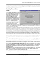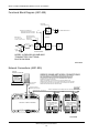
1
The way PC-based instrumentation should be
DI-900MB Series
Modbus/RS485 Network I/O Modules
Model DI-917MB
Quad Current Output
Model DI-918MB
Quad Voltage Input
User’s Manual
Copyright © 2003 by DATAQ Instruments, Inc. The Information contained herein is the exclusive property of DATAQ
Instruments, Inc., except as otherwise indicated and shall not be reproduced, transmitted, transcribed, stored in a
retrieval system, or translated into any human or computer language, in any form or by any means, electronic,
mechanical, magnetic, optical, chemical, manual, or otherwise without expressed written authorization from the company. The distribution of this material outside the company may occur only as authorized by the company in writing.
DATAQ Instruments' hardware and software products are not designed to be used in the diagnosis and treatment of
humans, nor are they to be used as critical components in any life-support systems whose failure to perform can reasonably be expected to cause significant injury to humans.
Windows 95/98 & NT are registered trademarks of Microsoft Corporation. Modbus is a registered trademark of
Modicon, Inc.
241 Springside Dr., Suite #200
Akron, Ohio 44333 U.S.A.
Telephone: 330-668-1444
Fax: 330-666-5434
Designed and manufactured in the
United States of America
Warranty and Service Policy
Product Warranty
DATAQ Instruments, Inc., warrants the instruments described in this manual to be free from defects in materials and
factory workmanship to the original buyer. This warranty is contingent upon proper use of the equipment, and does
not cover equipment that has been modified or has been subjected to abusive physical or electrical stresses. DATAQ
Instruments, Inc., agrees to repair or replace, at its sole discretion, any instrument that fails to perform as specified
within 18 months after date of the original shipment from the factory, or 12 months after the date of installation,
whichever date comes first.
DATAQ Instruments, Inc., reserves the right to make substitutions and modifications in the specifications of equipment that do not materially or adversely affect the performance of the equipment.
New equipment may be returned within 30 days of shipment with prior factory approval and upon the assignment of
a Returned Material Authorization number, RMA number, by DATAQ Instruments, Inc. This number must be clearly
shown on the return package(s). RMA numbers are valid for 30 days from date of issue. New items in factory sealed
containers which are less than thirty days old after shipment may be returned for credit, less a minimum restocking
and testing charge of twenty percent of the list price upon factory approval only, provided the customer pays all shipping and handling charges. Specially ordered, or modified goods, or goods which have been used or have been
unpacked from the factory-sealed containers, or goods which have been shipped more than thirty days prior are not
returnable.
The information contained in this manual is subject to change without notice. DATAQ Instruments, Inc., makes no
warranty of any kind with regard to this material, including, but not limited to, the implied warranties of merchantability and fitness for a particular purpose. Further, DATAQ Instruments, Inc., assumes no responsibility for any
errors that may appear in this manual and makes no commitment to update, or keep current, the information contained
in this manual.
Service Policy
Units within the warranty period returned for repair, test, and recalibration are serviced at no charge in accordance
with the terms of the warranty policy. The Customer pays all transportation and other charges to the factory.
Units out of warranty returned for repair, test, and/or recalibration are handled on a time and material basis. If
requested, or if costs exceed 50% of current list price, DATAQ Instruments, Inc., advises the customer prior to making
the repairs. Such repairs are performed at the customer’s expense. Typical test, recalibration, and repairs are 25% of
the instrument’s current list price. Transportation charges both ways are at the customer’s expense.
Please be sure all returns are shipped with the following information included:
1.
“Returned Material Authorization,” RMA number, clearly shown on each package. Please call DATAQ Instruments, Inc., at 330-668-1444 to obtain your RMA number.
2.
Your company Name with Billing and Shipping Addresses.
3.
A complete description of your problem, or re-calibration data.
4.
The contact person at your company, with their telephone and facsimile numbers.
5.
Non-Warranty returns additionally need your Purchase Order Number.
Please pack your returned instruments in their original shipping cartons, or in equivalent strong protective shipping
cartons.
Service and Repair Assistance
This module contains solid-state components and requires no maintenance, except for periodic cleaning and transmitter configuration parameter (zero, full-scale, setpoint, deadband, etc) verification. Since Surface Mount Technology
(SMT) boards are generally difficult to repair, it is highly recommended that a non-functioning module be returned to
DATAQ Instruments Inc., for repair. The board can be damaged unless special SMT repair and service tools are used.
Further, DATAQ Instruments, Inc., has automated test equipment that thoroughly checks and calibrates the performance of each module. Please contact DATAQ Instruments, Inc., for complete details on how to obtain service parts
and repair..
CAUTION: Risk of Electric Shock - More than one disconnect switch may be
required to de-energize the equipment before servicing.
Preliminary Service Procedure
Before beginning repair, be sure that all installation and configuration procedures have been followed. Make sure
that the correct baud rate is selected for the RS232-to-RS485 converter employed. The unit routinely performs internal diagnostics following power-up or reset. During this period, the green “Run” LED flashes.
If the diagnostics complete successfully, the “Run” LED will stop flashing after two seconds and remain ON. This
indicates that the unit is operating normally. If the “Run” LED continues to flash, then this is indicative of a problem.
In this case, use the Modbus Configuration Software to reconfigure the module and this will usually cure the problem.
If the diagnostics continue to indicate a problem (a continuously flashing green LED), or if other evidence points to a
problem with the unit, an effective and convenient fault diagnosis method is to exchange the questionable module
with a known good unit. DATAQ Instruments' Application Engineers can provide further technical assistance if
required. When needed, complete repair services are available from DATAQ Instruments, Inc.
Safety Summary
!
Means “Caution, refer to this manual for additional information.”
IMPORTANT SAFETY CONSIDERATIONS
It is very important for the user to consider the possible adverse effects of power, wiring, component, sensor,
or software failures in designing any type of control or monitoring system. This is especially important
where economic property loss or human life is involved. It is important that the user employ satisfactory
overall system design. It is agreed between the Buyer and DATAQ Instruments, Inc., that this is the Buyer’s
responsibility.
Model 917MB/918MB Modbus/RS485 Network I/O Modules
Table of Contents
Warranty and Service Policy ................................................................................................................ iii
1. Introduction ........................................................................................................................................ 1
Description ......................................................................................................................................... 1
Key 917MB/918MB Module Features: ............................................................................................. 2
2. Specifications ...................................................................................................................................... 3
General ............................................................................................................................................... 3
Model Number Definition ................................................................................................................. 3
Analog Output Specifications ............................................................................................................ 3
Digital Output Specifications ............................................................................................................ 5
Enclosure/Physical Specifications ..................................................................................................... 6
Approvals (-xxx0) .............................................................................................................................. 6
Environmental Specifications ........................................................................................................... 6
Communication Interface Specifications ........................................................................................... 8
Configuration and Controls ............................................................................................................... 9
Software Configuration ..................................................................................................................... 9
Other Modbus Configuration Software Capabilities ......................................................................... 11
3. Getting Started ................................................................................................................................... 13
Unpacking and Inspection ................................................................................................................. 13
Module Installation ............................................................................................................................ 13
Default Mode Switch .................................................................................................................. 14
Mounting ..................................................................................................................................... 14
Electrical Connections ................................................................................................................ 14
Software Installation—Using Setup.exe ............................................................................................ 15
4. Module Configuration ....................................................................................................................... 17
Register Map ...................................................................................................................................... 17
Module Calibration ............................................................................................................................ 21
5. An Introduction to Modbus ............................................................................................................... 23
Remote Terminal Unit (RTU) Mode ................................................................................................. 23
Modbus Message Framing ................................................................................................................. 23
How Characters Are Transmitted Serially ......................................................................................... 24
Modbus Addresses ............................................................................................................................. 24
Modbus Functions ............................................................................................................................. 24
Read Coil Status (01) .................................................................................................................. 25
Read Holding Registers (03) ....................................................................................................... 25
Read Input Registers (04) ........................................................................................................... 26
Force Single Coil (05) ................................................................................................................. 26
Preset Single Register (06) .......................................................................................................... 27
Force Multiple Coils (15) ............................................................................................................ 27
Preset Multiple Registers (16) ..................................................................................................... 28
Report Slave ID (17) ................................................................................................................... 29
Reset Slave (08) .......................................................................................................................... 30
Modbus Data Field ............................................................................................................................ 30
Supported Data Types ....................................................................................................................... 30
Modbus Error Checking Fields .......................................................................................................... 31
Parity Checking ................................................................................................................................. 31
Table of Contents
v
Model 917MB/918MB Modbus/RS485 Network I/O Modules
CRC Error Checking ..........................................................................................................................
Modbus Exceptions ...........................................................................................................................
6. Module Software Configuration .......................................................................................................
Before You Begin ..............................................................................................................................
Starting The Program .........................................................................................................................
File ...............................................................................................................................................
Module ........................................................................................................................................
Settings ........................................................................................................................................
Help .............................................................................................................................................
Creating A Configuration File ...........................................................................................................
Module ........................................................................................................................................
Watchdog Timeout States/Values ......................................................................................................
Testing Your Configuration ...............................................................................................................
Test Operation .............................................................................................................................
Print Your Configuration ............................................................................................................
Saving Your Configuration .........................................................................................................
Output Calibration .............................................................................................................................
Output Calibration Procedure .....................................................................................................
7. Block Diagrams and Schematics .......................................................................................................
Theory of Operation ..........................................................................................................................
Simplified Schematic (4501-828) ......................................................................................................
Functional Block Diagram (4501-829) ..............................................................................................
Network Connections (4501-805) .....................................................................................................
Electrical Connections (4501-831) ....................................................................................................
Interposing Relay Conn. & Contact Pro. (4501-832) ........................................................................
Enclosure Dimensions (4501-833) ....................................................................................................
8. Accessories ..........................................................................................................................................
Series DI-900MB Software Interface Package (Model 100969) .......................................................
DI-900MB Configuration & Control Software ...........................................................................
RS-232 to RS-485 Serial Adapter ...............................................................................................
Interface Cable ............................................................................................................................
Isolated Signal Converter (Models 100974 and 100975) ..................................................................
Isolated Network Repeater (Models 100977 and 100978) ................................................................
Table of Contents
vi
31
32
33
33
34
34
34
34
35
35
35
37
38
38
38
39
39
40
41
41
41
42
42
43
43
44
45
45
45
45
45
45
45
Model 917MB/918MB Modbus/RS485 Network I/O Modules
1. Introduction
These instructions cover the hardware functionality of the transmitter models listed in the table below. Supplementary sheets are attached for units with special options or features.
Models Covered in This Manual
Series/Input Type
DI-917MB
DI-918MB
-Options/Output/Enclosure/ Approvals1
-0900
-0900
-Factory Configuration2
-C
-C
Notes:
1. Agency approvals include CE, UL Listed, and cUL Listed.
2.
Include the “-C” suffix to specify factory configuration option. Otherwise, no suffix is required for standard configuration.
Description
The DI-900MB family is a group of process I/O modules and accessories for Modbus/RS485 network I/O applications. The Model DI-917MB and DI-918MB provide control of four analog output channels, plus four digital output
channels, via an isolated RS485 network I/O path utilizing the industry standard Modbus protocol. The Model DI917MB drives four channels of process current, while the DI-918MB drives four channels of voltage output signals.
Both models also include four control outputs for simple ON/OFF control of external devices. The DI-917MB/DI918MB modules contain an advanced technology microcontroller with integrated downloadable flash and EEPROM
memory for non-volatile program, configuration, calibration, and parameter data storage. Units are fully reconfigurable via our user-friendly Windows 95/98® or NT® Configuration Program and the RS485 interface, or other compatible Modbus software. Once configured, these modules may operate as an active RS485 network slave connected
to other modules and a host computer.
Each module provides four isolated analog outputs for DC process current or voltage signals. The module uses four
12-bit DAC’s to generate separate channel voltage signals. In addition, four open-drain mosfets provide discrete control of external devices. Outputs may be automatically programmed to user-defined levels or states following a
watchdog timer timeout. The open-drain outputs include yellow LED’s at the front of the module that provide visual
indication of output state. Additionally, a green “Run” and yellow “Status” LED provide local feedback of operating
mode, system diagnostics, watchdog status, and module status.
All DI-900MB modules are designed to withstand harsh industrial environments. They feature RFI, EMI, ESD, EFT,
and surge protection, plus low temperature drift, wide ambient temperature operation, and isolation between signal I/
O, power, and the network. They also have low radiated emissions per CE requirements.
As wide-range DC-powered devices, these units may be powered from DC power networks incorporating battery
backup. Since input power is diode-bridge coupled, the unit may be connected to redundant power supplies, or several units may safely share a single DC supply. The unit may also be powered from common 24VAC power.
Units are DIN-rail mounted and removable terminal blocks facilitate ease of installation and replacement, without
having to remove wiring. Transmitter power, network, and digital output wiring are inserted at one side of the unit,
while analog output wiring is inserted at the other side. Plug-in connectors are an industry standard screw clamp type
that accept a wide range of wire sizes.
Flexible transmitter functionality, network reprogrammability, mixed signal I/O, and a network interface, all combine
in a single package to make this instrument extremely powerful and useful over a broad range of applications. Further, the safe, compact, rugged, reconfigurable, and reliable design of this transmitter makes it an ideal choice for
control room or field applications. Custom module configurations are also possible (please consult the factory).
Introduction
1
Model 917MB/918MB Modbus/RS485 Network I/O Modules
Key 917MB/918MB Module Features:
•
Agency Approvals - CE, UL, & cUL Listings pending.
•
Easy Windows® Configuration - Fully configurable via our user-friendly Windows 95/98® or NT® DI-900MB
Configuration Program.
•
RS485/Modbus Network Interface - This proven high speed interface is highly immune to noise, can operate
over long distances, and allows a large number of modules to be networked together. The unit communicates
using the industry-standard Modbus command/response protocol.
•
Nonvolatile Reprogrammable Memory - This module has an advanced technology microcontroller with integrated, non-volatile, downloadable flash memory and EEPROM. This allows the functionality of this device to
be reliably reprogrammed thousands of times.
•
Fully Isolated - Output circuitry, network, & power are isolated from each other for safety and increased noise
immunity.
•
Discrete Outputs - High voltage, high current, open-drain mosfets provide direct control of external devices.
Outputs may be activated independently, or under watchdog timeout control.
•
Flexible Process Current Output (DI-917MB) - Generates up to four process current signals in three ranges.
•
Flexible DC Voltage Output (DI-918MB) - Generates up to four DC voltage signals in three ranges.
•
Watchdog Timer - An output watchdog timer function is included and may be configured for timeout periods up
to 65534 seconds (18.2 hours). Timer will timeout if a read or write operation to any I/O channel does not occur
over the configured time period. Outputs may be automatically set to user-defined levels or states following a
watchdog timeout.
•
Self-Diagnostics - Built-in routines operate upon power-up for reliable service, easy maintenance, and troubleshooting. A watchdog timer is also built into the microcontroller that causes it to initiate a self reset if the controller ever “locks up” or fails to return from an operation in a timely manner.
•
High-Speed Data Rates - Supports RS485 communication rates up to 115K baud.
•
Wide-Range DC-Power or 24VAC Power - This device receives power over a wide supply range and the
power terminals are diode coupled. This makes this transmitter useful for systems with redundant supplies, and/
or battery back-up. Additionally, the power terminals are not polarized.
•
Wide Ambient Operation - The unit is designed for reliable operation over a wide ambient temperature range.
•
Hardened For Harsh Environments - The unit will operate reliably in harsh industrial environments and
includes protection from RFI, EMI, ESD, EFT, and surges, plus low radiated emissions per CE requirements.
•
Convenient Mounting, Removal, & Replacement - The DIN-rail mount and plug-in type terminal blocks make
module removal and replacement easy.
•
High-Resolution Precise D/A Conversion - Transmitters include high-resolution, low noise, Digital-to-Analog
Converters for high accuracy and reliability.
•
LED Indicators - A green LED indicates power. A yellow status LED will flash if the unit is placed in the
default communication mode. It will also flash rapidly upon watchdog timeout. A yellow output LED indicates
the ON/OFF state of the associated open-drain output.
•
Default Communication Mode - A push-button switch is provided to set the module to a default set of communication parameters for baud rate, module address, parity, and number of stop bits. This provides a convenient
way of establishing communication with the module when its internal settings are unknown.
Introduction
2
Model 917MB/918MB Modbus/RS485 Network I/O Modules
2. Specifications
General
The Model DI-917MB & DI-918MB are DC-powered or 24VAC powered network transmitters which drive up to
four analog output signals (current or voltage), plus four open-drain output switches, and provide an isolated RS485/
Modbus network interface. Isolation is supplied between the output circuit (as a group), the network, and power.
The outputs may operate as discrete on/off controls for external devices. This transmitter is DIN-rail mounted.
The unit is configured and calibrated with our user-friendly Windows 95/98® or NT® DI-900MB Configuration Program. Optionally, you may use your own software as long as you adhere to the Modbus command/response format
for supported commands. A push button on the module allows communication with a module when its address,
baud rate, and parity settings are unknown. Non-volatile reprogrammable memory in the module stores calibration
and configuration information.
Model Number Definition
Transmitters are color coded with a white label. The prefix “9” denotes the Series 900, while the “MB” suffix specifies that this device is primarily a process transmitter for Modbus networks.
DI-917MB: Transmits up to four DC current output channels, plus four digital outputs.
DI-918MB: Transmits up to four DC voltage output channels, plus four digital outputs.
-0900: The four digits of this model suffix represent the following options, respectively:
0 = No Options;
9 = Output: RS485/Modbus;
0 = Enclosure: DIN rail mount;
0 = Approvals (Pending): CE, UL Listed, and cUL Listed.
Analog Output Specifications
Each output channel of these models includes a 12-bit DAC (Digital-to-Analog Converter) that drives a voltage to
current converter (DI-917MB model), or voltage amplifier (DI-918MB model). The unit must be wired and configured for the intended output type and range (see Module Installation for details). The unit can be easily reconfigured
to accept any one of the output ranges described below using the Modbus Configuration Program. Analog outputs
go to their minimum levels following a software or power-on reset of the module, but may be optionally sent to userdefined levels following a watchdog timer timeout. The following paragraphs summarize this model's output ranges
and applicable specifications.
Current Output Specifications
(DI-917MB Only)
Output Ranges: Select 0-20mA DC, 4-20mA DC, or 0-1mA DC. Ranges are sub-ranges of
nominal 0-22.67mA design limit (includes approximately 12.5% of overrange).
Note: The 0-20mA & 0-1mA output ranges may not precisely go to the 0mA
endpoint. The 0-20mA range will typically approach 0mA within 0.1% of
span.
Output Maximum Current: 22.67mA typical.
Output Accuracy: See Table: “Analog Output Range Resolution & Accuracy” on page 5
Output Compliance: 12V Minimum, 13V Typical.
Specifications
3
Model 917MB/918MB Modbus/RS485 Network I/O Modules
Output Load Resistance Range: 0 to 625Ω, typical.
Response Time: 11ms typical into 500Ω, for measurement to reach 98% of the final value in
response to a step command. Actual response time will vary with load.
Output Resolution: 12 bits, or 1 part in 4096 based 22.67mA full-scale. This is 5.535uA/bit
(22.67mA/4096bits). See below for effective resolution calculations.
DAC Count (Current): The internal DAC count can be calculated by multiplying the output current by
180680. The resultant value (rounded) can be used to calculate the effective
resolution and to approximate the required output register program value (see
below).
Internal DAC Count Versus Current Output Range
Range
DAC 0%
DAC 100%
0-1mA
0
181
4-20mA
723
3614
0-20mA
0
3614
DAC Span
181
2891
3614
Note that the effective resolution is 1 part in the DAC Span.
Register Program Value: Output values use integers with ±20000 representing ±100%. The required
output register program value can be approximated using the DAC values
shown above via the formula:
Register Value = 20000 * (DAC Count - DAC 0%)/DAC Span
Current Output Register Program Value
Output Current
0mA
1mA
4mA
Range
0-1mA
4-20mA
0-20mA
0
--0
20000
--1000
--0
4000
12mA
20mA
--10000
12000
--20000
20000
Voltage Output Specifications
(DI-918MB Only)
Output Range: 0-10V DC, 0-5V DC, or 0-1V DC. Ranges are sub-ranges of nominal 0-11.3V
design limit (includes approximately 13% of over-range).
Output Maximum Voltage: 11.3V, typical.
Output Accuracy: See Table: “Analog Output Range Resolution & Accuracy” on page 5.
Output Current: 0-10mA DC maximum.
Output Impedance: 1Ω.
Output Short Circuit Protection: Included
Response Time: 110us rise time typical, 150us fall time typical, unloaded, for output to reach
98% of the final value in response to a step command. Actual response time
will vary with load.
Output Resolution: 1 part in 4046 based on 11.368V full-scale, or 2.81mV/bit (11.368V/4046bits).
DAC Count (Voltage): The internal DAC count can be calculated by multiplying 355.96 by the sum of
the output voltage and 0.1393. The resultant value (rounded) can be used to
calculate the effective resolution and to approximate the required output register program value (see below).
Specifications
4
Model 917MB/918MB Modbus/RS485 Network I/O Modules
Internal DAC Count Versus Voltage Output Range
Range
DAC 0%
DAC 100%
0-1V
50
406
0-5V
50
1829
0-10V
50
3609
DAC Span
356
1779
3559
Note that the effective resolution is 1 part in the DAC Span.
Register Program Value: Output values use integers with ±20000 representing ±100%. The required
output register program value can be approximated using the DAC values
shown above via the following formula:
Register Value = 20000 * (DAC Count - DAC 0%)/DAC Span
Current Output Register Program Value
Output Voltage
0V
1V
2.5V
Range
0-1V
0-5V
0-10V
0
--0
20000
4000
2000
--10000
5000
5V
10V
--20000
10000
----20000
General Output Specifications
Accuracy: Accuracy is better than ±0.1% of span, typical, for 4-20mA, 0-20mA, 0-10V,
and 0-5V ranges (see Table: “Analog Output Range Resolution & Accuracy”
on page 5). This includes the effects of repeatability, terminal point conformity, and linearization.
Resolution: See Table: “Analog Output Range Resolution & Accuracy” on page 5.
Ambient Temperature Effect: Better than ±.01% of output span per °C (±100ppm/°C), or ±1.0uV/°C, whichever is greater.
Digital-to-Analog Converter: Burr-Brown DAC7615, 12-bit. Monotonic to 12 bits.
Integral Non-Linearity: ±0.1% of span or ±2LSB typical, whichever is larger, for spans equal to or
greater than 16mA (DI-917MB) or 5V (DI-918MB).
Analog Output Range Resolution & Accuracy
Calibrated Out Range
Effective Resolution
Accuracy Percent-of-Span
Model DI-917MB
0 to 20mA DC
.028%, 1/3614
±0.1% span (±0.02mA)
4 to 20mA DC
.035%, 1/2891
±0.1% span (±0.02mA)
0 to 1mA DC
.552%, 1/181
±1.6% span (±0.002mA)
Model DI-918MB
0-10V DC
.028%, 1/3559
±0.1% span (±10mV)
0-5V DC
.056%, 1/1779
±0.1% span (±5mV)
0-1V DC
.281%, 1/356
±0.8% span (±8mV)
Digital Output Specifications
Four open-drain outputs are installed in this module and operate as discrete outputs (coils) for control of external
devices. Digital outputs go to their OFF state following a software or power-on reset of the module, but may be
optionally sent to user-defined states following a watchdog timer timeout.
Note: To control a higher amperage device, such as a pump, an interposing relay may be used (see Drawing Interposing Relay Conn. & Contact Pro. (4501-832)).
Specifications
5
Model 917MB/918MB Modbus/RS485 Network I/O Modules
Output Channel Configuration: Output Channel Configuration: Four open-drain mosfet switches which share
a common return (source) connection at the RTN terminal. For DC voltage and
current sinking applications only--observe proper polarity. To control higher
voltage and/or current, or for controlling AC, an interposing relay may be used
(see Drawing Electrical Connections (4501-831)).
Output “OFF” Voltage Range: 0-35V DC continuous, 47Vpk.
Output “OFF” Leakage Current: 0.1uA typical, 50uA maximum (25°C, 40VDC).
Output “ON” Current Range: 0 to +1A DC, continuous, for each output switch (group one RTN per each
group of 2 outputs). No deration required at elevated temperatures.
Output Rds ON Resistance: 0.15Ω Maximum (25°C, 1A).
Output Response Time: Outputs will switch within 5ms typical, upon receiving a control command.
Output Over-Temperature Protec- Outputs will turn-off if the junction temperature of the device exceeds 165°C.
tion: Cycling the output off/on will restart the output.
Output Over-Current Protection: Outputs will turn-off if the drain current reaches 5A. Cycling the output off/on
will restart the output.
Enclosure/Physical Specifications
See Drawing Enclosure Dimensions (4501-833). Units are packaged in a general purpose plastic enclosure that is
DIN rail mountable for flexible, high density (approximately 1" wide per unit) mounting.
Dimensions: Width = 1.05 inches, Height = 4.68 inches, Depth = 4.35 inches (see Drawing
Enclosure Dimensions (4501-833)).
DIN Rail Mounting (-xx0x): DIN rail mount, Type EN50022; “T” rail (35mm)
Connectors: Removable plug-in type terminal blocks; Current/Voltage Ratings: 15A/300V;
Wire Range: AWG #12-24, stranded or solid copper; separate terminal blocks
are provided for analog outputs, discrete outputs, and power & network. For
supply connections, use No. 14 AWG copper wires rated for at least 75°C.
Case Material: Self-extinguishing NYLON type 6.6 polyamide thermoplastic UL94 V-2, color
beige; general purpose NEMA Type 1 enclosure.
Printed Circuit Boards: Military grade FR-4 epoxy glass.
Shipping Weight: 1 pound (0.45 Kg) packed.
Approvals (-xxx0)
0: Agency Approvals Pending - CE, UL Listed, and cUL Listed. UL3121 First
Edition, CSA C22.2 No. 1010.1-92, Low Voltage Directive (72/23/EEC), EMC
(89/336/EEC) Directives.
Product approval is limited to general safety requirements of the above standards.
Warning: This product is NOT approved for hazardous location applications.
Environmental Specifications
Operating Temperature: DI-917MB: -25°C to +60°C (-13°F to +140°F), limit DI-917MB ambient to
50°C maximum for supply voltages less than 15V
DI-918MB: -25°C to +70°C (-13°F to +158°F).
Storage Temperature: -40°C to +85°C (-40°F to +185°F).
Relative Humidity: 5 to 95% non-condensing.
Specifications
6
Model 917MB/918MB Modbus/RS485 Network I/O Modules
Power Requirements: Non-polarized 12-36V DC SELV (Safety Extra Low Voltage), or 22-26 VAC.
Current draw is a function of supply voltage and model number (see Supply
Current Tables below). Current shown below assumes that all outputs are ON
(LED's ON), the module is connected to the network, and module is in the
default mode. The power terminals are diode coupled and are not polarized.
Caution: Do not exceed 36VDC peak, to avoid damage to the module.
The DI-917MB current in the table below assumes that all four current outputs are delivering 20mA. Note the DI917MB maximum ambient is derated to 50°C for supply voltages less than 15V.
DI-917MB Supply Current
Supply
DI-917MB
10V
Not Recommended
12V
256mA Typical, 275mA Maximum*
15V
183mA Typical, 200mA Maximum
24V
108mA Typical, 120mA Maximum
36V
75mA Typical, 80mA Maximum
24VAC
190mA rms Typical, 210mA rms Maximum
The DI-918MB current in the table below assumes that all four voltage outputs are driving 10V into 10KΩ.
DI-918MB Supply Current
Supply
DI-918MB
10V
125mA Typical, 140mA Maximum
12V
100mA Typical, 115mA Maximum
15V
80mA Typical, 90mA Maximum
24V
52mA Typical, 60mA Maximum
36V
40mA Typical, 45mA Maximum
24VAC
96mA rms Typical, 105mA rms Maximum
Power Supply Effect
Volts: Less than ±0.001% of output span change per volt for rated power supply variations.
60/120 Hz Ripple: Less than 0.01% of output span per volt peak-to-peak of power supply ripple.
Isolation: Output, network, and power circuits are isolated from each other for commonmode voltages up to 250VAC, or 354V DC off DC power ground, on a continuous basis (will withstand 1500VAC dielectric strength test for one minute
without breakdown). This complies with test requirements of ANSI/ISA82.01-1988 for the voltage rating specified.
Installation Category: Designed to operate in an Installation Category (Overvoltage Category) II
environment per IEC 1010-1 (1990).
Radiated Field Immunity (RFI): Designed to comply with IEC1000-4-3 Level 3 (10V/M, 80 to 1000MHz AM
& 900MHz keyed) and European Norm EN50082-1.
Electromagnetic Interference No output shifts will occur beyond ±0.25% of span under the influence of EMI
Immunity (EMI): from switching solenoids, commutator motors, and drill motors.
Specifications
7
Model 917MB/918MB Modbus/RS485 Network I/O Modules
Electrical Fast Transient Immunity Complies with IEC1000-4-4 Level 3 (2KV power; 1KV signal lines) and Euro(EFT): pean Norm EN50082-1.
Electrostatic Discharge (ESD) Complies with IEC1000-4-2 Level 3 (8KV/4KV air/direct discharge) to the
Immunity: enclosure port and European Norm EN50082-1.
Surge Immunity: Complies with IEC1000-4-5 Level 3 (2.0KV) and European Norm EN50082-1.
Radiated Emissions: Designed to comply with European Norm EN50081-1 for class B equipment.
Communication Interface Specifications
These units contain an isolated RS485 communication port for the transmission of data.
Interface Standard: RS-485. Communication with this module is made over a 3-wire cable (D, Dbar, and Common).
Command/Response Protocol: Standard Modbus RTU protocol implemented as defined under “Modicon
Modbus Reference Guide” PI-MBUS-300 Rev J (reference www.public.modicon.com, search keyword PI-MBUS-300 to obtain technical publication). See
4. Module Configuration for a review of Modbus & commands.
Baud Rate: Can be programmed for 2400, 4800, 9600 (Default Mode), 14400, 19200,
28800, 38400, 57600, 76800, or 115200 bits per second.
Duplex: Half Duplex only.
Parity: Odd, Even, or None (Default Mode).
Stop Bits: 1 stop bit for even/odd parity, 2 stop bits w/ no parity.
Response Delay: The minimum communication turnaround delay that a module will wait before
it sends its response to a message from the host. It is applied in addition to the
inherent delay already present which varies between models. It can be set from
0-65500 ticks, with 1 tick equivalent to 1.085us. Some signal converters or
host/software systems cannot accept an immediate response from the slave
without additional delay. Note that you may have to specify an amount of
delay that is comparable to the inherent delay already present before an effect
can be measured.
Module Address: Can be set from 0-247 (01H-F7H). The Default Mode address is 247 (F7H).
Network Capacity: The Module has multi-drop capability for up to 31 modules, plus host, without
use of an RS485 repeater. If a signal repeater is used for every 31 nodes, up to
247 modules may be networked, plus a host computer.
Communication Distance: Up to 4000 feet without a repeater. Distance can be extended with the use of a
signal repeater.
Default Communication Mode In this mode, the module address is 247, the baud rate is 9600bps, the parity is
Parameters: none, and the number of stop bits is set to 2 by pressing the DFT push-button
on the front of the module until the yellow Status LED flashes ON/OFF. This
is provided as a means to communicate with a module when its internal
address, baud rate, parity, and stop bit settings are unknown. Exit the Default
Mode by pressing this button until the Status LED is NOT flashing (constant
ON or OFF), or by issuing a software or power-on reset. New parameters for
module address, baud rate, and parity do not take effect outside of Default
Mode until after a software or power-on reset.
Specifications
8
Model 917MB/918MB Modbus/RS485 Network I/O Modules
Watchdog Timer: A hardware watchdog timer is built into the microcontroller that causes it to
initiate a self reset if the controller ever fails to return from an operation in a
timely manner or “locks up.” Additionally, an output watchdog timer function
is implemented that may be configured for timeout periods up to 65534 seconds (18.2 hours). The output watchdog timer will cause the status LED to
blink rapidly, set a bit in the Module Status Register, and optionally program
the outputs to a pre-defined state or level upon watchdog timeout. The output
watchdog timer is reinitiated via a read or write to any output channel.
Supported Modbus Commands: The command & response protocol for communicating with this module
adheres to the Modbus/RTU standard for the following Modbus Functions. The
register reference addresses that the function operates on is also indicated (see
4. Module Configuration).
Code
01 (01H)
03 (03H)
04 (04H)
05 (05H)
06 (06H)
08 (08H)
15 (0FH)
16 (10H)
17 (11H)
Function
Read Coil (Output) Status
Read Holding Registers
Read Input Registers
Force Single Coil (Output)
Preset Single Register
Reset Slave
Force Multiple Coils (Outputs)
Preset Multiple Registers
Report Slave ID
Reference
0xxxx
4xxxx
3xxxx
0xxxx
4xxxx
Hidden
0xxxx
4xxxx
Hidden
Configuration and Controls
Module Push Button (See Drawing Default (DEF) - Push to engage or disengage the default communication mode
Enclosure Dimensions (4501-833) with baud rate set to 9600bps, module address set to 247, and no parity
For Location): selected. The Status LED will flash ON/OFF when the module is in the default
mode. A module will leave the default mode following a software or power-on
reset (Status LED will be OFF or constant ON).
LED Indicators: Run (Green) - Constant ON indicates power is applied and unit is operating
normally. Flashing ON/OFF indicates unit is performing diagnostics (first second following power-up), or has failed diagnostics (after a few seconds).
Status (Yellow) - Flashing ON/OFF indicates the module is in the default Communication Mode. Upon watchdog timer timeout, this LED will flash rapidly
and may temporarily mask default mode indication.
Output (Yellow) - One per open-drain output. OFF if output switch is OFF
(open), ON if output switch is ON (sinking current).
Software Configuration
Units are fully reprogrammable via our user-friendly Windows 95/98® or NT® 900MB Configuration Program. See
Drawing Network Connections (4501-805). The following transmitter attributes are configurable via the DI900MB Configuration Software. Optionally, any software that supports the Modbus command/response protocol
may be used. Use the Preset Single/Multiple Register functions to write configuration data to the appropriate register(s) as required by your application (see Register Map).
Specifications
9
Model 917MB/918MB Modbus/RS485 Network I/O Modules
Slave Communication
Slave - ID: The Report Slave ID command will return the model number, run on/off status,
module serial number, and firmware number.
Slave - Reset: This command is used to trigger a reset of the module and its effect is equivalent to a power-on reset. An alternate method of resetting a module can be
accomplished via a write to the Calibration Access & Reset Register. This is
provided to accomplish reset with software that does not support the Reset
Slave command.
Slave - Address: Select valid slave addresses in the range of 1-247 (01H-F7H). Address 247 is
the default mode address.
Slave - Baud Rate: Select 2400, 4800, 9600 (default), 14400, 19200, 28800, 38400, 57600, 76800,
or 115200 bits per second.
Slave - Parity: Select Even, Odd, or No Parity (See Parity Checking) error checking. Odd or
even parity bit is followed by 1 stop bit. Two stop bits are used if no parity is
selected.
Slave - Response Delay: Can be set from 0-65500 ticks (1 tick = 1.085us) and refers to the additional
delay a module will wait before it sends its response to a message from the
host. Some signal converters or host/software systems cannot accept a
response to a message immediately after sending the message without additional delay.
Slave - Status: The Module Status Register can be used to determine internal flash or
EEPROM checksum error status.
Slave - Watchdog: A watchdog timer may be applied to the output channels of this module. Use
the Watchdog Time Register to select a timeout period from 1 to 65534 seconds
(18.2 hours). A time of 65535 (FFFFH) or 0 (0000H) will disable the output
watchdog timer. Use the Timeout States Register to define the states that the
outputs of the port are to be programmed to upon output timeout (the four
lower order bits of this register value define the timeout states of each of the
output channels). Writing 65535 (FFFFH) to the output channel Timeout
States register will leave the port outputs unchanged upon timeout. Use the
Timeout Value registers to set a level that the corresponding analog output is to
be programmed to following a watchdog timeout. Write 65535 (FFFFH) to
this register to leave the analog outputs unchanged following a timeout.
Watchdog timeout state or level control takes precedence over direct control of
the output channels of this model. The output watchdog timer is reinitiated via
a read or write to any output channel.
Analog Output
Output - Range/Type: DI-917MB: Select DC current output ranges 4-20mA, 0-20mA, or 0-1mA.
DI-918MB: Select DC voltage output ranges 0-10V, 0-5V, or 0-1V DC.
Outputs use percent of span units with ±20000 representing ±100% (see Units
below).
Output - Timeout Value: The value that the corresponding analog output will be automatically programmed to following a watchdog timer timeout. This value must be within
the programmed output range. Write 32767 (7FFFH) to leave the output
unchanged following a watchdog timeout.
Output Calibration: The configuration software can be used to calibrate the output circuit of this
module (see Output Calibration), or by using the Preset Register Functions to
write the appropriate data to the calibration registers (see Register Map).
Specifications
10
Model 917MB/918MB Modbus/RS485 Network I/O Modules
Output Units: Analog output values are expressed as a 16-bit signed integer value representing percent-of-span (resolution of 0.005%/lsb). The range is -163.84% (-32768
decimal) to +163.835% (+32767 decimal). For example, -100%, 0% and
+100% are represented by decimal values -20000, 0, and 20000, respectively.
Digital Outputs
Output - State: The coil registers (0x references) may be read via the Read Coil (01) command
to determine the current state of the outputs. The current output state is also
indicated by a yellow status LED at the front of the module which lights when
the corresponding output is sinking current. The Force Single Coil (05) and
Force Multiple Coil (15) commands may be used to directly control the output
state via the coil registers.
Output - Timeout State: The state that the corresponding discrete output will be automatically programmed to following a watchdog timeout.
Output Visual Indication: Yellow output LED's provide visual status indication of the current state of the
corresponding output channel (LED is ON when switch is ON and sinking current).
Other Modbus Configuration Software Capabilities
In addition to configuring all features of the module described above, the Modbus Configuration Software includes
additional capabilities for testing and control of this module as follows:
1.
Monitors and controls analog output signal values and the discrete output signal states. It also allows polling to
be turned on or off.
2.
Allows a configuration to be uploaded or downloaded to/from the module via the RS485 interface.
3.
Provides controls to separately calibrate each output.
4.
Provides control to reset a module.
5.
Provides control to restore a module's original default factory output calibration in case of miscalibration.
6.
Reads the contents of the Module Status Register.
7.
Allows optional user documentation to be assigned to a module the module. Documentation fields are provided
for tag number, comment, configured by, location, and identification information. This information can also be
uploaded from the module and printed via this software.
8.
Allows a module's complete configuration to be printed in an easy to read, one-page format, including user documentation.
Specifications
11
Model 917MB/918MB Modbus/RS485 Network I/O Modules
3. Getting Started
Unpacking and Inspection
Upon receipt of this product, inspect the shipping carton for evidence of mishandling during transit. If the shipping
carton is badly damaged or water stained, request that the carrier's agent be present when the carton is opened. If the
carrier's agent is absent when the carton is opened and the contents of the carton are damaged, keep the carton and
packing material for the agent's inspection. For repairs to a product damaged in shipment, refer to the Warranty and
Service Policy to obtain return instructions. It is suggested that salvageable shipping cartons and packing material be
saved for future use in the event the product must be shipped.
This module is physically protected with packing material and electrically
protected with an anti-static bag during shipment. However, it is recommended that the module be visually inspected for evidence of mishandling
prior to applying power.
This circuit utilizes static sensitive components and should only be handled
at a static-safe workstation.
Module Installation
This transmitter module is packaged in a general purpose plastic enclosure. Use an auxiliary enclosure to protect the
unit in unfavorable environments or vulnerable locations, or to maintain conformance to applicable safety standards.
Stay within the specified operating temperature range. As shipped from the factory, the unit is calibrated for all valid
input ranges and has the default configuration shown in the table below.
WARNING: Applicable IEC Safety Standards may require that this device be mounted within an approved metal
enclosure or sub-system, particularly for applications with exposure to voltages greater than or equal to 75VDC or
50VAC.
DI-918MB Default Factory Configuration
Parameter
Configuration/Calibration
Module Address
247
Baud Rate
9600bps
Parity
None (2 stop bits w/No parity)
Stop Bits
2 (When Parity=None)
Response Delay
0 (No Delay)
Output Range (Each Output)
0-20mA (DI-917MB)
0-10V (DI-918MB)
Watchdog Time
0 (Timer Disabled)
Analog Output Timeout Level
0 (Each Output)
Discrete Output Timeout State
1/ON (Each Output)
Note: Do not confuse the Default Factory Configuration noted above with the Default Communication Mode, which
refers to the fixed baud rate, module address, parity, and stop bit settings achieved by pushing the Default Mode button until the yellow status LED flashes ON/OFF. The Default Communication Mode will temporarily over-ride any
factory configuration of baud rate, module address, parity, and stop bits with settings of 9600bps, 247, None, and 2,
respectively. It is provided as a convenient means of achieving communication with a module when these parameters
are unknown.
Your application will typically differ from the default factory configuration and will require that the transmitter be
reconfigured to suit your needs. This can be easily accomplished with the user-friendly Windows 95/98® or NT® DI-
Getting Started
13
Model 917MB/918MB Modbus/RS485 Network I/O Modules
900MB Configuration Program. Configuration is normally done prior to field installation. Refer to 6. Module Software Configuration for detailed instructions.
Default Mode Switch
A push-button default mode switch (DFT) and status LED are provided at the front of the module as a convenient
way of communicating with the module when its baud rate and address settings are unknown. Push and hold this button until the Status LED flashes ON/OFF to indicate the module is in the Default Communication Mode with a fixed
module address of 247, baud rate of 9600bps, no parity, and 2 stop bits. It is most convenient to configure a module
in this mode, then leave the default mode by pressing this button again until the Status LED stops flashing (constant
ON or OFF), or by resetting the module. The Default Mode is disabled following a software or power-on reset. New
communication parameters (baud rate, address, & parity) will take effect following a module reset after leaving the
Default Mode.
Mounting
Refer to Drawing Enclosure Dimensions (4501-833) for mounting and clearance dimensions.
DIN Rail Mounting: This module can be mounted on “T” type DIN rails. Use suitable fastening hardware to secure
the DIN rail to the mounting surface. Units may be mounted side-by-side on 1-inch centers for limited space applications.
“T” Rail (35mm), Type EN50022: To attach a module to this style of DIN rail, angle the top of the unit towards the
rail and locate the top groove of the adapter over the upper lip of the rail. Firmly push the unit towards the rail until it
snaps solidly into place. To remove a module, first separate the input terminal block(s) from the bottom side of the
module to create a clearance to the DIN mounting area. Next, insert a screwdriver into the lower arm of the DIN rail
connector and use it as a lever to force the connector down until the unit disengages from the rail.
Electrical Connections
Analog output, digital output, and network & power terminals can accommodate wire from 12-24 AWG, stranded or
solid copper. Strip back wire insulation ¼-inch on each lead before installing into the terminal block. Analog output
wiring should be shielded twisted-pair. Since common mode voltages can exist on signal wiring, adequate wire insulation should be used and proper wiring practices followed. It is recommended that analog output wiring, digital output wiring, network wiring, and power wiring be separated from each other for safety, as well as for low noise pickup.
Note that terminal blocks are a plug-in type and can be easily removed to facilitate module removal or replacement,
without removing individual wires. Be sure to remove power before unplugging the terminals to uninstall the module, or before attempting service. All connections must be made with power removed.
CAUTION: Risk of Electric Shock - More than one disconnect switch may be
required to de-energize the equipment before servicing.
1.
Power: Refer to Drawing Electrical Connections (4501-831). Variations in power supply voltage within rated
limits has negligible effect on module accuracy. For supply connections, use No. 14 AWG wires rated for at least
75°C. The power terminals are diode bridge-coupled and not polarized. The unit is powered from 10-36VDC,
or 24VAC.
2.
Analog Outputs: Connect outputs per Drawing Electrical Connections (4501-831). Observe proper polarity
when making connections (see label for output type).
Note: Analog outputs go to their minimum levels following a software or power-on reset of the module. Outputs may be optionally sent to user-defined levels following a watchdog timer timeout.
3.
Digital Outputs (Coils): All discrete outputs are the open-drains of n-channel mosfets whose source terminals
share return (RTN). Externally wired drain pullups or other load is generally required. All outputs include transient voltage suppressers and integrated snubbers, but may require additional protection when switching inductive loads (see below). Refer to the Digital Output Specifications section for output specifications and see the
module side label for terminal designations. Note that these outputs are for current-sinking (low-side switching)
Getting Started
14
Model 917MB/918MB Modbus/RS485 Network I/O Modules
applications only. Digital outputs are turned OFF following a software or power-on reset of the module, but can
be optionally programmed to user-defined states following a watchdog timer timeout. Observe proper polarity
when making connections. The output circuitry as a group is electrically isolated from the network and power
circuits. If necessary, an interposing relay can be used to switch higher currents as illustrated in the Interposing
Relay Connection Drawing 4501-832.
Note: Digital outputs go to their OFF state following a software or power-on reset of the module. Outputs may
be optionally sent to user-defined states following a watchdog timer timeout.
IMPORTANT - Protection With Inductive Loads: The output mosfets have integrated shunt diode clamps
connected from drain to source to help protect the output switch from damaging reverse emf voltages that exist
when controlling inductive loads. You may need to add external protection local to the inductive load for added
protection and to prevent this emf from being distributed across the connection media. For DC inductive loads,
place a diode across the load (1N4006 or equivalent) with cathode to (+) and anode to (-).
4.
Network Connections: Wire network as shown in Network Connections Drawing 4501-805. Network common
(COM) should connect to earth ground at one point.
5.
Grounding: See Drawing Electrical Connections (4501-831). The module housing is plastic and does not
require an earth ground connection.
WARNING: For compliance to applicable safety and performance standards, the use
of shielded cable is recommended as shown in Drawing 4501-831. Further, the application of earth ground must be in place as shown in Drawing 4501-831. Failure to
adhere to sound wiring and grounding practices may compromise safety & performance.
Software Installation
The 900MB Configuration Software is used to configure Series DI-900MB modules and is installed as follows:
1.
Insert the DI-900MB Resource CD into your CD-ROM drive.
IMPORTANT: Before continuing with installation, be sure to exit any other Windows programs that may be
running.
2.
The Window’s AutoRun feature should start the CD and the installation software will run.
3.
Select the option “Install DI-900MB Configuration Software” and click on OK.
4.
The Welcome Dialog Box appears. Click on Next to continue with the installation or Cancel to abort.
5.
Fill out your user information in the appropriate text boxes and click on Next.
6.
The Choose Destination dialog box allows you to specify the program files’ destination directory. To keep the
default (C:\Program Files\Series900MB) click on Next, to change the destination click on the Browse button,
select a destination, then click on Next.
7.
The Select Program Folder allows you to designate the program folder. To keep the default (Series900MB),
click on Next, to choose a different folder, make a selection from the list then click on Next.
8.
The Start Copying Files dialog box shows the current settings and allows you to change them by using the Back
button. To change settings, click on the Back button until you reach the setting you would like to change, change
that setting, and click on the Next button until you get back to the Start Copying Files dialog box. To keep the
current settings and install the software, click on the Next button.
Getting Started
15
Model 917MB/918MB Modbus/RS485 Network I/O Modules
9.
Setup is complete. Click Finish to exit the DATAQ installation program and return to Windows.
10. To run the configuration software, go to the Start Menu and click on Programs > Series900MB > Series900MB
Configuration (this is the default - if you did not keep the default settings choose the program folder and directory you had specified during installation).
Getting Started
16
Model 917MB/918MB Modbus/RS485 Network I/O Modules
4. Module Configuration
This module needs to be configured for your application. Configuration is easily accomplished using the Windows
95/98® or NT® Modbus Configuration Software and an RS232-to-RS485 signal converter. It is not required to use
the DATAQ software to communicate with the Series DI-900MB, as any software capable of sending Modbus network
protocol commands over an RS485 network can be used. However, the Configuration Software does provide an easy
to use Windows format for communicating with the module that does not require advanced familiarity with the Modbus protocol.
Register Map
Modbus registers are organized into the following reference types identified by the leading number of the reference
address:
Reference
0xxxx
1xxxx
3xxxx
4xxxx
Description
Read/Write Discrete Outputs or Coils. A 0x reference address is used to drive output data
to a digital output channel.
Read Discrete Inputs. The ON/OFF status of a 1x reference is controlled by the corresponding digital input channel.
Read Input Registers. A 3x reference register contains a 16-bit number received from an
external source-e.g. an analog signal.
Read/Write Output or Holding Registers. A 4x register is used to store 16-bits of numerical data (binary or decimal), or to send the data from the CPU to an output channel.
Notes:
1.
The “x” following the leading character represents a four-digit address location in user data memory. The leading character is generally implied by the function code and omitted from the address specifier for a given function. The leading character also identifies the I/O data type.
2.
The ON/OFF state of discrete inputs and outputs is represented by a 1 or 0 value assigned to an individual bit in
a 16-bit data word. This is sixteen 0x or 1x references per data word. With respect to mapping, the LSB of the
word maps to the lowest numbered channel of a group and channel numbers increase sequentially as you move
towards the MSB. Unused bits are set to zero.
Modbus functions operate on register map registers to configure and control modules. The following table outlines
the register map for Model DI-917MB and DI-918MB network I/O modules. You will find it helpful to review this
map as you review the Modbus function descriptions.
Ref
Addr.
Description
Coil Registers (0x References, Read/Write)
00001
0-3
Four Discrete Outputs 0-3, Program
Thru
(0000States
00004
0003)
Data Type/Format
Discrete Output Value. Addresses a specific bit of a 16-bit word
that controls/ monitors the ON/OFF status for the output.
A set bit (1) means the corresponding output is ON. A clear bit (0)
means the corresponding output is OFF. The bit position corresponds to the output channel number (i.e. output 0 uses bit 0 of the
16-bit word at address 0, output 1 uses bit 1 of the 16-bit word at
address 1, etc.) Unused bits of a word are set to 0.
Bits 15-4: Not Used. Additionally, unused bits in range 3-0 are set
to 0.
Note: This signal corresponds to the gate signal of the n-channel output mosfet. Thus, a read of this register may
not reflect the actual output level at the drain of the mosfet if the open-drain is not pulled up or is left floating (no
excitation). Excitation must be provided in order to operate the outputs.
After reset, these registers read 0 (outputs OFF) and these registers are not maintained in EEPROM.
Module Configuration
17
Model 917MB/918MB Modbus/RS485 Network I/O Modules
Ref
Addr.
Description
Data Type/Format
Input Registers (3x References, Read-Only)
30001
0 (0000)
Module Status
Bit 15: Flash Checksum; 1 = Error Flag; 0 = No Flash Error
Bit 14: Not Used
Bit 13: Default Mode; 1 = Default Mode Indicator; 0 = Not In
Default Mode
Bits 12-1: Zero
Bit 0: Watchdog Fault; 1 = Watchdog Timeout; 0 = Timeout
Cleared
30002
1 (0001)
CH 0 Status Value
Bits 15-2: Zero
(DI-917MB)
Bits 1,0: Output Range
00 = 0 = 0-20mA
01 = 1 = 4-20mA
10 = 2 = 0-1mA
11 = 3 = Reserved
30002
1 (0001)
CH0 Status Value
Bits 15-2: Zero
(DI-918MB)
Bits 1,0: V-Output Range
00 = 0 = 0-10V
01 = 1 = 0-5V
10 = 2 = 0-1V
11 = Reserved
30003
2 (0002)
CH1 Status Value
Format Is Same As CH 0
30004
3 (0003)
CH2 Status Value
Format Is Same As CH 0
30005
4 (0004)
CH3 Status Value
Format Is Same As CH 0
30006
5 (0005)
CH0 Raw Count
Raw DAC Count Value (See Module Calibration)
30007
6 (0006)
CH1 Raw Count
Raw DAC Count Value (See Module Calibration)
30008
7 (0007)
CH2 Raw Count
Raw DAC Count Value (See Module Calibration)
30009
8 (0008)
CH3 Raw Count
Raw DAC Count Value (See Module Calibration)
Holding Registers (4x References, Read/Write)
40001
0 (0000)
Slave Address
1-247
Default=247
40002
1 (0001)
Baud Rate
0 = 2400bps
Default = 2
1 = 4800bps
9600bps
2 = 9600bps (Default)
3 = 14400bps
4 = 19200bps
5 = 28800bps
6 = 38400bps
7 = 57600bps
8 = 76800bps
9 = 115200bps
40003
2 (0002)
Parity
0 = No Parity Check
Default=0, None
1 = Odd Parity Checking
2 = Even Parity Checking
40004
3 (0003)
Output Watchdog
Can be set from 1 to 65534 seconds. Set to 65535 (FFFFH) or 0
Time Default=0, Dis- (0000H) to disable the watchdog timer.
abled
Module Configuration
18
Model 917MB/918MB Modbus/RS485 Network I/O Modules
Ref
40005
Addr.
4 (0004)
Description
Digital Output Channel Watchdog Timeout States
Default=65535, Disabled
Data Type/Format
The four lower order bits of this 16-bit register value define the
state the output channels will be programmed to following a
watchdog timeout. Timeout control of the outputs will take precedence over alarm and direct control. Bit 0 corresponds to channel
0, bit 1 to channel 1, bit 2 to channel 2, and bit 3 to channel 4.
Write 65535 (FFFFH) to this register to leave the outputs
unchanged following a timeout (this is also the default value).
Note: Clearing a timeout via an I/O read or write does not return the output(s) to their initial state or level. They
remain at their timeout state or level until otherwise written.
40006
5 (0005)
Response Delay
Can be set from 0 to 65500 ticks (1 tick = 1.085us). This is the
Time (Turnaround
additional delay the module will wait before responding to a mesDelay) Default=0,
sage from the host. Increase this value if you have trouble comNo Delay
municating with the module or you encounter a high degree of
error messages.
40007
6 (0006)
CH 0 Output Value
Percentage (%).2 After reset, this register reads 0 and this register
Default=0
is not maintained in EEPROM.
40008
7 (0007)
CH 0 Timeout Value Percentage (%).2 Write 32767 (7FFFH) to leave output unaffected
Default=0
by a watchdog timeout.
40009
8 (0008)
CH0 Output Config- Bits 15-2: Zero
uration (DI-917MB) Bits 1,0: I-Output Range
Default=0, 0-20mA
00 = 0 = 0-20mA
01 = 1 = 4-20mA
10 = 2 = 0-1mA
11 = Reserved
Note that the 0-20mA range may not precisely go to the 0mA endpoint. It will typically approach 0mA within 0.1%.
40009
8 (0008)
CH0 Output Config- Bits 15-2: Zero
uration (DI-918MB) Bits 1,0: V-Output Range
Default=0, 0-10V
00 = 0 = 0-10V
01 = 1 = 0-5V
10 = 2 = 0-1V
11 = Reserved
40010
9 (0009)
CH 1 Output ValuePercentage (%).2 After reset, this register reads 0 and this register
Default=0
is not maintained in EEPROM.
40011 10 (000A) CH 1 Timeout Value- Percentage (%).2 Write 32767 (7FFFH) to leave output unaffected
Default=0
by a watchdog timeout.
40012 11 (000B) CH1 Output Config- Bits 15-2: Zero
uration (DI-917MB) Bits 1,0: I-Output Range
Default=0, 0-20mA
00 = 0 = 0-20mA
01 = 1 = 4-20mA
10 = 2 = 0-1mA
11 = Reserved
Note that the 0-20mA range may not precisely go to the 0mA endpoint. It will typically approach 0mA within 0.1%.
40012 11 (000B) CH1 Output Config- Bits 15-2: Zero
uration (DI-918MB) Bits 1,0: V-Output Range
Default=0,0-10V
00 = 0 = 0-10V
01 = 1 = 0-5V
10 = 2 = 0-1V
11 = Reserved
40013 12 (000C)
CH 2 Output Value
Percentage (%).2
Default=0
Module Configuration
19
Model 917MB/918MB Modbus/RS485 Network I/O Modules
Ref
40014
Addr.
13 (000D)
Description
CH 2 Timeout Value
Default=0
40015
14 (000E)
CH2 Output Configuration (DI-917MB)
Default=0, 0-20mA
40015
14 (000E)
CH2 Output Configuration (DI-918MB)
Default=0, 0-10V
40016
15 (000F)
40017
16 (0010)
CH 3 Output Value
Default=0
CH 3 Timeout ValueDefault=0
40018
17 (0011)
CH3 Output Configuration (DI-917MB)
Default=0, 0-20mA
40018
17 (0011)
CH3 Output Configuration (DI-918MB)
Default=0, 0-10V
40019
18 (0012)
Calibration Access
And
Alternate Method of
Module Reset
40020
40021
40022
40023
40024
40025
40026
40027
19 (0013)
20 (0014)
21 (0015)
22 (0016)
23 (0017)
24 (0018)
25 (0019)
26 (001A)
CH0 Cal High Value
CH0 Cal Low Value
CH1 Cal High Value
CH1 Cal Low Value
CH2 Cal High Value
CH2 Cal Low Value
CH3 Cal High Value
CH3 Cal Low Value
Data Type/Format
Percentage (%).2 Write 32767 (7FFFH) to leave output unaffected
by a watchdog timeout.
Bits 15-2: Zero
Bits 1,0: I-Output Range
00 = 0 = 0-20mA
01 = 1 = 4-20mA
10 = 2 = 0-1mA
11 = Reserved
Note that the 0-20mA range may not precisely go to the 0mA endpoint. It will typically approach 0mA within 0.1%.
Bits 15-2: Zero
Bits 1,0: V-Output Range
00 = 0 = 0-10V
01 = 1 = 0-5V
10 = 2 = 0-1V
11 = Reserved
Percentage (%).2
Percentage (%).2 Write 32767 (7FFFH) to leave output unaffected
by a watchdog timeout.
Bits 15-2: Zero
Bits 1,0: I-Output Range
00 = 0 = 0-20mA
01 = 1 = 4-20mA
10 = 2 = 0-1mA
11 = Reserved
Note that the 0-20mA range may not precisely go to the 0mA endpoint. It will typically approach 0mA within 0.1%.
Bits 15-2: Zero
Bits 1,0: V-Output Range
00 = 0 = 0-10V
01 = 1 = 0-5V
10 = 2 = 0-1V
11 = Reserved
Writing 24106 (5E2AH) here immediately removes write protection from the calibration registers that follow. All other values
apply write protection to the calibration registers (except 41429).
Writing 41429 (A1D5H) to this register will cause an immediate
module reset. This is provided as an alternate method of Reset for
software that does not support the Reset Slave (08) command.
After a reset, this register reads 0 (write protection enabled and no
reset).
This register is not maintained in EEPROM.
Raw DAC Value Register (See Module Calibration)
Raw DAC Value Register (See Module Calibration)
Raw DAC Value Register (See Module Calibration)
Raw DAC Value Register (See Module Calibration)
Raw DAC Value Register (See Module Calibration)
Raw DAC Value Register (See Module Calibration)
Raw DAC Value Register (See Module Calibration)
Raw DAC Value Register (See Module Calibration)
Module Configuration
20
Model 917MB/918MB Modbus/RS485 Network I/O Modules
Notes (Register Map):
1.
Note that the Report Slave ID and Reset Slave functions do not operate on Register Map locations.
2.
Output values are indicated in percent-of-span units represented by a 16-bit signed integer value with resolution
of 0.005%/lsb. The range is -163.84% (-32768 decimal) to +163.835% (+32767 decimal). For example, -100%,
0% and +100% are represented by the decimal values -20000, 0, and 20000, respectively. Clearing a watchdog
timeout does not return an output to its pre-timeout level, it remains at its timeout level until otherwise written.
3.
Configuration variables stored in holding registers (4xxxx reference addresses) are maintained in EEPROM,
except for the Calibration Access & Reset Register and Output Value Registers. Changes to configuration registers do not take effect until the next software or power-on reset of the module.
4.
WARNING: Access to register entries 40020 to 40027 are normally not required and writes to these registers
should be avoided to prevent module miscalibration.
Module Calibration
Series DI-917MB/DI-918MB Analog Output Modules are calibrated using a single output range with fixed calibration points. The calibration of the model's sub-ranges are interpolated based on these results. Prior to calibration, DI917MB units must have the 0-20mA output range selected, while DI-918MB units must have the 0-10V output range
selected. Calibration is performed by adjusting the output signal level until its measured value precisely matches the
low or high calibration point. With the output level precisely adjusted to the low or high calibration point, the output
channel's Raw DAC Count is then read from the module (registers 30006-30009 of the Memory Map). This same
value is then written to the corresponding channel's respective Cal High or Cal Low register (registers 40020-40027
of Memory Map). Note that you will have to write 24106 into the Calibration Access register to be able to modify the
Cal High/Low registers. This process is repeated for the opposite calibration point. After writing the required values
to the Cal Low & Cal High registers of the output, the new output calibration will take effect immediately following a
module reset. For best results, allow some settling time between Low & High calibration and always calibrate the
low calibration point first.
Output Calibration Values For DI-917MB/DI-918MB
Output
Factory Calibration LOW Point
Range
Output
Output %
DAC Count
0-20mA
4.000mA
4000
723
0-10V
0.000V
0
50
Output
Range
0-20mA
0-10V
Factory Calibration HIGH Point
Output
Output %
DAC Count
20.000mA
20000
3614
10.000V
20000
3609
Note that DI-917MB units have the 0-20mA output range selected during calibration, while DI-918MB units have the
0-10V output range selected during calibration. The output % value and DAC count of the table are based on “ideal”
conditions and will only approximate random selected performance.
IMPORTANT: Because calibration of the module’s sub-ranges are interpolated based on the primary range calibration noted above, and because resolution is degraded for the sub-ranges, it is very important that high accuracy be
ensured for the primary range calibration when making output adjustments and measuring the output levels. Further,
resolution limits of the output sub-ranges may make it difficult to accurately adjust the output level to the ideal range
endpoints (especially for 0-1mA and 0-1V output ranges). The inability to precisely attain endpoint values will
increase total error at the endpoints.
5. An Introduction to Modbus provides a description of the Modbus protocol and the Modbus functions that apply to
this model.
Module Configuration
21
Model 917MB/918MB Modbus/RS485 Network I/O Modules
5. An Introduction to Modbus
The Modbus protocol provides an industry standard method that Series DI-900MB modules use for parsing messages. Modbus devices communicate using a master-slave technique in which only one device (the master) can initiate transactions (called queries). The other devices (slaves) respond by supplying the requested data to the master,
or by taking the action requested in the query. The Series DI-900MB modules are slaves, while a typical master
device is a host computer running appropriate application software. Masters can address individual slaves, or can initiate a broadcast message to all slaves. Slaves return a response to all queries that are addressed to them individually,
but no response is returned to broadcast queries from a master device.
Remote Terminal Unit (RTU) Mode
The Series DI-900MB modules use the widely accepted Modbus network protocol in the RTU (Remote Terminal
Unit) serial transmission mode. In RTU mode, each 8-bit message byte contains two 4-bit hexadecimal characters,
and the message is transmitted in a continuous stream. The format for each byte in RTU mode is outlined below:
RTU Mode Byte Format
Coding System
8-bit binary, hexadecimal 0-9, A-F, two hexadecimal characters contained in
each 8-bit field of the message.
Bits Per Byte
1 start bit + 8 data bits, lsb sent first + 1bit for even/odd parity or no bit for no
parity + 1 stop bit if parity is used or 2 stop bits with no parity.
Error Check Field
Cyclical Redundancy Check (CRC)
A master’s query is comprised of a slave address (or broadcast address), a function code defining the requested
action, any required data, and an error checking field. A slave's response is comprised of fields confirming the action
taken, any data to be returned, and an error checking field. The query and response both include a device address +
function code + data byte(s) + error checking field. If an error occurred in the receipt of the query, or if the slave is
unable to perform the requested action, the slave will return an exception message as its response (see Modbus
Exceptions). The error check field allows the master to confirm that the message contents are valid.
Modbus Message Framing
A Modbus message is placed in a frame by the transmitting device. A frame is used to mark the beginning and ending point of a message allowing the receiving device to determine which device is being addressed and to know when
the message is completed. It also allows partial messages to be detected and errors flagged as a result.
RTU mode messages start with a silent interval of at least 3.5 character times implemented as a multiple of character
times at the baud rate being used on the network (indicated as t1t2t3t4 below). The first field transmitted is the device
address. The allowable characters transmitted for all fields are hexadecimal values 0-9, A-F. A networked device
continuously monitors the network, including the silent intervals, and when the first field is received (the address),
the device decodes it to determine if it is the addressed device. Following the last character transmitted, a similar
silent interval of 3.5 character times marks the end of the message and a new message can begin after this interval. A
typical message frame is shown below.
RTU Message Frame
Start
Addr.
t1t2t3t4
8 bits
Function
8 bits
Data
nx8 bits
CRC
16 bits
End
t1t2t3t4
The entire message must be transmitted as a continuous stream. If a silent interval of more than 1.5 character times
occurs before completion of the frame, the receiving device flushes the incomplete message and assumes the next
byte will be the address field of a new message.
An Introduction to Modbus
23
Model 917MB/918MB Modbus/RS485 Network I/O Modules
In similar fashion, if a new message begins earlier than 3.5 character times following a previous message, the receiving device assumes it is a continuation of the previous message. This will generate an error, as the value in the final
CRC field will not be valid for the combined messages.
How Characters Are Transmitted Serially
When messages are transmitted on Modbus serial networks, each character or byte is sent in the order of Least Significant Bit (LSB) to Most Significant Bit (MSB) as outlined below (moving left to right). Note that an additional stop
bit is transmitted to fill out the character frame for no parity.
RTU Character Framing (No Parity)
Start
0
1
2
3
4
5
6
7
Stop
Stop
RTU Character Framing (With Parity)
Start
0
1
2
3
4
5
6
7
Parity
Stop
Modbus Addresses
The master device addresses a specific slave device by placing the 8-bit slave address in the address field of the message. Valid addresses are from 1-247. When the slave responds, it places its own address in this field of its response
to let the master know which slave is responding. Address 0 is reserved for the broadcast address, which all slave
devices on a network recognize. A slave does not issue a response to broadcast messages. Further, not all function
messages support the broadcast address.
With respect to data addresses, all data addresses in Modbus messages are referenced to 0, with the first occurrence of
a data item addressed as item number zero. Further, a function code field already specifies which register group it is
to operate on (i.e. 0x, 1x, 3x, or 4x reference addresses). For example, holding register 40001 is addressed as register
0000 in the data address field of the message. The function code that operates on this register specifies a “holding
register” operation and the “4xxxx” reference is implied. Holding register 40108 is addressed as register 006BH (107
decimal).
Modbus Functions
The function code field of a message frame contains the 8 bits that tell the slave what kind of action to take. Valid
codes are in the range 1-255. Not all codes apply to a module and some codes are reserved for future use. The following table highlights the subset of standard Modbus functions supported by the Model DI-918MB module (the reference register addresses that the function operates on are also indicated):
Code
01 (01H)
03 (03H)
04 (04H)
05 (05H)
06 (06H)
08 (08H)
15 (0FH)
16 (10H)
17 (11H)
Function
Read Coil (Output) Status
Read Holding Registers
Read Input Registers
Force Single Coil (Output)
Preset Single Register
Reset Slave
Force Multiple Coils (Outputs)
Preset Multiple Registers
Report Slave ID
Reference
0xxxx
4xxxx
3xxxx
0xxxx
4xxxx
Hidden
0xxxx
4xxxx
Hidden
These functions are used to access the registers outlined in the Register Map for sending and receiving data. Note
that the Report Slave ID and Reset Slave commands do not operate on register map registers.
When the slave device responds to the master, it uses the function code field to indicate either a normal (error-free)
response, or that some kind of error has occurred (an exception response). A normal response simply echoes the original function code of the query, while an exception response returns a code that is equivalent to the original function
code with its most significant bit (msb) set to a logic 1. For example, the Read Holding Registers command has the
An Introduction to Modbus
24
Model 917MB/918MB Modbus/RS485 Network I/O Modules
function code 0000 0011 (03H). If the slave device takes the requested action without error, it returns the same code
in its response. However, if an exception occurs, it returns 1000 0011 (83H) in the function code field and also
appends a unique code in the data field of the response message that tells the master device what kind of error
occurred, or the reason for the exception (See Modbus Exceptions). The master's application program must handle
the exception response. It may choose to post subsequent retries of the original message, it may try sending diagnostic messages to the slave, or it may simply notify the operator an exception error has occurred.
The following paragraphs describe the Modbus functions supported by the Model DI-918MB. To gain a better understanding of Modbus, please refer to the Register Map as you review this material.
Read Coil Status (01)
This command will read the ON/OFF status of discrete outputs or coils (0x reference addresses) in the slave. For DI918MB models, its response is equivalent to reading the gate signals of the n-channel mosfets that drive the outputs.
Broadcast transmission is not supported.
The Read Coil Status query specifies the starting coil (output channel) and quantity of coils to be read. Coils correspond to the discrete open-drain outputs of this transmitter and are addressed starting from 0 (up to 4 coils addressed
as 0-3 for this model).
The Read Coil Status in the response message is packed as one coil or channel per bit of the data field. The output
status is indicated as 1 for ON (sinking current), and 0 for OFF (not conducting). The LSB of the first data byte corresponds to the status of the coil addressed in the query. The other coils follow sequentially, moving toward the high
order end of the byte. Since this model has only 4 outputs, the remaining bits of the data byte will be set to zero
toward the unused high order end of the byte.
The following example reads the output channel status of coils 0-3 at slave device 247:
Read Coil Status Example Query
Field Name
Slave Address
Function Code
Starting Address High Order
Starting Address Low Order
Number Of Points High Order
Number Of Points Low Order
Error Check (CRC)
Read Coil Status Example Response
Field Name
Example Value
(Hex)
Slave Address
247 (F7)
Function Code
1 (01)
Byte Count
2 (02)
Data (Coils 3-0)
10 (0A)
Error Check (CRC)
--
Example
Value (Hex)
247 (F7)
1 (01)
0 (00)
0 (00)
0 (00)
4 (04)
--
Note that the leading character of the 0x reference address is implied by the function code and omitted from the
address specified. In this example, the first address is 00001, referenced via 0000H, and corresponding to coil 0.
To summarize, the status of coils 3-0 is shown as the byte value 0A hex, or 00001010 binary. Coil 3 is the fifth bit
from the left of this byte, and coil 0 is the LSB. The four remaining bits (toward the high-order end) are zero. Reading left to right, the output status of coils 3..0 is ON-OFF-ON-OFF. This is summarized as follows:
Bin
Hex
Coil
0
0
0
0
1
0
0
NA
NA
1
0
1
0
A
NA
NA
3
2
Read Holding Registers (03)
This command will read the binary contents of holding registers (4x reference addresses) in the slave device. Broadcast transmission is not supported.
The Read Holding Registers query specifies the starting register and quantity of registers to be read. Note that registers are addressed starting at 0 (registers 1-16 are addressed as 0-15). The Read Holding Registers response message
is packed as two bytes per register, with the binary contents right-justified in each byte. For each register, the first
byte contains the high order bits and the second byte the low order bits.
An Introduction to Modbus
25
Model 917MB/918MB Modbus/RS485 Network I/O Modules
The following example reads holding registers 40007…40009 (channel 0 output value, reset value, and output configuration) at slave device 247:
Read Holding Register Example Query
Field Name
Example
Value (Hex)
Slave Address
247 (F7)
Function Code
3 (03)
Starting Address High Order
0 (00)
Starting Address Low Order
8 (08)
Number Of Points High Order
0 (00)
Number Of Points Low Order
3 (03)
Error Check (CRC)
--
Read Holding Register Example Response
Field Name
Example Value
(Hex)
Slave Address
247 (F7)
Function Code
3 (03)
Byte Count
6 (06)
Data High (Register 40007)
(3A)
Data Low (Register 40007)
15000 (98)
Data High (Register 40008)
(27)
Data Low (Register 40008)
10000 (10)
Data High (Register 40009)
(00)
Data Low (Register 40009)
1 (01)
Error Check (CRC)
--
To summarize, the contents of register 40007 (two bytes) is the channel 0 output value of 15000 or 75% (3A98H).
The contents of register 40008 (two bytes) is the channel 0 reset value of 10000 or 50% (2710H). The contents of
register 40009 is the channel 0 output configuration value (two bytes) of 0-20mAV (0001H).
Note that the analog output value is expressed as a 16-bit signed integer value with resolution of 0.005%/lsb. The
range is -163.84% (-32768 decimal) to +163.835% (+32767 decimal). For example, -100%, 0% and +100% are represented by decimal values -20000, 0, and 20000, respectively.
Read Input Registers (04)
This command will read the binary contents of input registers (3x reference addresses) in the slave device. Broadcast
transmission is not supported.
The Read Input Registers query specifies the starting register and quantity of registers to be read. Note that registers
are addressed starting at 0--registers 1-16 are addressed as 0-15.
The Read Input Registers response message is packed as two bytes per register, with the binary contents right-justified in each byte. For each register, the first byte contains the high order bits and the second byte the low order bits.
The following example reads input register 30001 (module status) at slave device 247:
Read Input Register Example Query
Field Name
Example
Value (Hex)
Slave Address
247 (F7)
Function Code
4 (04)
Starting Address High Order
0 (00)
Starting Address Low Order
2 (02)
Number Of Points High Order
0 (00)
Number Of Points Low Order
2 (02)
Error Check (CRC)
--
Read Input Register Example Response
Field Name
Example Value
(Hex)
Slave Address
247 (F7)
Function Code
4 (04)
Byte Count
6 (06)
Data High (Register 30003) 0 (00)
Data Low (Register 30003) 80 (50)
Data High (Register 30004) 0 (00)
Data Low (Register 30004) 128 (80)
Error Check (CRC)
--
To summarize, the contents of register 30001 (two bytes) is the status value of zero (0000H)--i.e. no EEPROM or
flash checksum errors present.
Force Single Coil (05)
This command will force a single coil/output (ox reference address) ON or OFF. For broadcast transmission, this
function forces the same coil in all networked slaves.
The Force Single Coil query specifies the coil reference address to be forced, and the state to force it to. The ON/
OFF state is indicated via a constant in the query data field. A value of FF00H forces the coil to be turned ON (i.e.
An Introduction to Modbus
26
Model 917MB/918MB Modbus/RS485 Network I/O Modules
the gate of the corresponding n-channel mosfet is set high), and 0000H forces the coil to be turned OFF (i.e. the gate
of the corresponding output mosfet is set low). All other values are illegal and will not affect the coil. Note that coils
are referenced starting at 0-up to 4 coils are addressed as 0-3 for this model and this corresponds to the discrete output
channel number. The following example forces discrete output 3 ON at slave device 247:
Force Single Coil Example Query
Field Name
Slave Address
Function Code
Coil Address High Order
Coil Address Low Order
Force Data High Order
Force Data Low Order
Error Check (CRC)
Force Single Coil Example Response
Example
Value (Hex)
247 (F7)
5 (05)
0 (00)
3 (03)
255 (FF)
0 (00)
--
Field Name
Slave Address
Function Code
Coil Address High Order
Coil Address Low Order
Force Data High Order
Force Data Low Order
Error Check (CRC)
Example
Value (Hex)
247 (F7)
5 (05)
0 (00)
3 (03)
255 (FF)
0 (00)
--
The Force Single Coil response message is an echo of the query as shown above, returned after executing the force
coil command. No response is returned to broadcast queries from a master device.
Preset Single Register (06)
This command will preset a single holding register (4x reference addresses) to a specific value. Broadcast transmission is supported by this command and will act to preset the same register in all networked slaves.
The Preset Single Register query specifies the register reference address to be preset, and the preset value. Note that
registers are addressed starting at 0--registers 1-16 are addressed as 0-15.
The Preset Single Registers response message is an echo of the query, returned after the register contents have been
preset.
The following example writes a baud rate of 9600bps to holding register 40002 (Baud Rate) at slave device 247:
Preset Holding Register Example Query
Field Name
Slave Address
Function Code
Register Address High Order
Register Address Low Order
Preset Data High Order
Preset Data Low Order
Error Check (CRC)
Preset Holding Register Example Response
Example
Value (Hex)
247 (F7)
6 (06)
0 (00)
1 (01)
0 (00)
2 (02)
--
Field Name
Slave Address
Function Code
Register Address High Order
Register Address Low Order
Preset Data High Order
Preset Data Low Order
Error Check (CRC)
Example
Value (Hex)
247 (F7)
6 (06)
0 (00)
1 (01)
0 (00)
2 (02)
--
The response simply echoes the query after the register contents have been preset. No response is returned to broadcast queries from a master device.
Force Multiple Coils (15)
This command will simultaneously force a sequence of coils (0x reference addresses) either ON or OFF. Broadcast
transmission is supported by this command and will act to force the same block of coils in all networked slaves.
The Force Multiple Coils query specifies the starting coil reference address to be forced, the number of coils, and the
force data to be written in ascending order. The ON/OFF states are specified by the contents in the query data field.
A logic 1 in a bit position of this field requests that the coil turn ON, while a logic 0 requests that the corresponding
coil be turned OFF. Unused bits in a data byte should be set to zero. Note that coils are referenced starting at 0-up to
4 coils are addressed as 0-3 for this model and this also corresponds to the discrete output channel number.
An Introduction to Modbus
27
Model 917MB/918MB Modbus/RS485 Network I/O Modules
The Force Multiple Coils normal response message returns the slave address, function code, starting address, and the
number of coils forced, after executing the force instruction. Note that it does not return the byte count or force value.
The following example forces outputs 1 & 3 OFF, and 0 & 2 ON for coils 0-3 at slave device 247:
Force Multiple Coils Example Query
Field Name
Example Value (Hex)
Slave Address
247 (F7)
Function Code
15 (0F)
Coil Address High Order
0 (00)
Coil Address Low Order
0 (00)
Number Of Coils High Order
0 (00)
Number Of Coils Low Order
4 (04)
Byte Count
01
Force Data High (First Byte)
5 (05)
Error Check (CRC)
-Note that the leading character of the 0x reference address is implied by the function code and omitted from the
address specified.
In this example, the first address is 00001 corresponding to coil 0 and referenced via 0000H. Thus, the data byte
transmitted will address coils 3...0, with the least significant bit addressing the lowest coil in this set as follows (note
that the four unused upper bits of the data byte are set to zero):
Bin
Hex
Coil
0
0
0
0
0
1
0
NA
NA
0
1
1
0
5
NA
NA
3
2
Force Multiple Coils Example Response
Field Name
Example Value (Hex)
Slave Address
247 (F7)
Function Code
15 (0F)
Coil Address High Order
0 (00)
Coil Address Low Order
0 (00)
Number Of Coils High Order
0 (00)
Number Of Coils Low Order
4 (04)
Error Check (CRC)
-The normal response returns the slave address, function code, starting coil address, and quantity of coils forced, after
executing the force instruction. It does not return the byte count or force data. No response is returned to broadcast
queries from a master device.
Preset Multiple Registers (16)
This command will preset a block of holding registers (4x reference addresses) to specific values. Broadcast transmission is supported by this command and will act to preset the same block of registers in all networked slaves.
The Preset Multiple Registers query specifies the starting register reference address, the number of registers, and the
data to be written in ascending order. Note that registers are addressed starting at 0--registers 1-16 are addressed as 015. The Preset Multiple Registers normal response message returns the slave address, function code, starting register
reference, and the number of registers preset, after the register contents have been preset. Note that it does not echo
the preset values.
The following example writes a new slave address of 200, a baud rate of 28800bps, and sets parity to even, by writing
to holding registers 40001 through 40003 at slave device 247 (changes to slave address, baud rate, and parity will take
effect following the next software or power-on reset):
An Introduction to Modbus
28
Model 917MB/918MB Modbus/RS485 Network I/O Modules
Preset Multiple Registers Example Query
Field Name
Slave Address
Function Code
Starting Register High Order
Starting Register Low Order
Number Of Registers High Order
Number Of Registers Low Order
Preset Data High (First Register)
Preset Data Low (First Register)
Preset Data High (Second Reg)
Preset Data Low (Second Reg)
Preset Data High (Third Reg)
Preset Data Low (Third Reg)
Error Check (CRC)
Preset Multiple Registers Example Response
Example
Value (Hex)
247 (F7)
16 (10)
0 (00)
0 (00)
0 (00)
3 (03)
0 (00)
200 (C8)
0 (00)
5 (05)
0 (00)
2 (02)
--
Field Name
Slave Address
Function Code
Starting Register High Order
Starting Register Low Order
Number Of Registers High Order
Number Of Registers Low Order
Error Check (CRC)
Example
Value (Hex)
247 (F7)
16 (10)
0 (00)
0 (00)
0 (00)
3 (03)
--
The response simply echoes the query without returning the preset values after the register contents have been preset.
No response is returned to broadcast queries from a master device.
Report Slave ID (17)
This command returns the model number, serial number, and firmware number for a slave device, the status of the
Run indicator, and any other information specific to the device. This command does not address Register Map registers. Broadcast transmission is not supported.
The Report Slave ID query simply sends the slave address and function code with error check (CRC) as follows:
Report Slave ID Example Query
Field Name
Slave Address
Function Code
Error Check (CRC)
Example
Value (Hex)
247 (F7)
17 (11)
--
Report Slave ID Example Response
Field Name
Slave Address
Function Code
Byte Count
Slave ID
Run Indicator Status (ON)
An Introduction to Modbus
29
Example Value (Hex)
247 (F7)
17 (11)
26 (1A)
0 (00H) = 924MB-0900
1 (01H) = 913MB-0900
2 (02H) = 914MB-0900
3 (03H) = 917MB-0900
4 (04H) = 918MB-0900
5 (05H) = 901MB-0900
6 (06H) = 902MB-0900
7 (07H) = 903MB-0900
8 (08H) = 904MB-0900
9 (09H) = 905MB-0900
10 (0AH) = 906MB-0900
255 (FF)
Model 917MB/918MB Modbus/RS485 Network I/O Modules
Firmware Number ASCII
Byte String (Additional
Data Field)
Serial Number ASCII Byte
String (Unique Per Module)
Error Check (CRC)
"ACROMAG, 9300-037A,
917MB-0900,"(41 43 52 4F 4D
41 47 2C 39 33 30 30 2D 30 33
37 41 2C 39 31 37 4D 42 2D 30
39 30 30 2CH)
Six Numbers + Revision
"123456A"(31 32 33 34 35 36
41H)
--
The Report Slave ID response message returns the slave model ID and firmware number string as shown above.
Reset Slave (08)
This command is used to trigger a reset of the module and its effect is equivalent to a power-on reset of the module.
Note that changes to baud rate, slave address, and parity are initiated following reset. The Reset Slave command uses
sub-function 01 (Restart Communications) of the standard Modbus Diagnostics Command (08) to accomplish a module reset. This function does not operate on register map locations. Broadcast transmission is not supported.
The Reset Slave query simply sends the slave address, function code, sub-function code, and data (data is ignored and
simply echoed back), with error check (CRC). A Reset Slave response is simply an echoed acknowledge that is
returned just before the reset is executed. Allow a few seconds following reset to re-initiate communication with a
module.
Reset Slave Example Query
Field Name
Slave Address
Function Code
Sub-Function High Order Byte
Sub-Function Low Order Byte
Data Field High-Order Byte
Data Field Low Order Byte
Error Check (CRC)
Reset Slave Example Response (Sent Prior To Reset)
Example
Value (Hex)
247 (F7)
08 (08)
0 (00)
1 (01)
0 (00)
0 (00)
--
Field Name
Slave Address
Function Code
Sub-Function High Order Byte
Sub-Function Low Order Byte
Data Field High-Order Byte
Data Field Low Order Byte
Error Check (CRC)
Example Value
(Hex)
247 (F7)
08 (08)
0 (00)
1 (01)
0 (00)
0 (00)
--
Note that the response simply echoes the query just before the reset is triggered.
For Modbus software that does not support the Reset Slave function, an alternate method of generating a module reset
is provided via a write to the Calibration Access & Module Reset Register (See Register 40020 of Register Map).
Modbus Data Field
The data field of a message frame contains a multiple of 8 bits that provides the slave with any additional information
the slave requires to complete the action specified by the function code. The data field typically includes register
addresses, count values, and written data. The data field can be nonexistent for some commands (zero length), as not
all messages require data.
If no error occurs, the data field of a response from a slave will return the requested data. If an error occurs, the data
field returns an exception code (see Modbus Exceptions) that the master application can use to determine the next
action to take.
Supported Data Types
All I/O values are accessed via 16-bit Input Registers or 16-bit Holding Registers (see Register Map). Input registers
contain information that is read-only. For example, the current input value read from a channel, or the states of a
An Introduction to Modbus
30
Model 917MB/918MB Modbus/RS485 Network I/O Modules
group of digital inputs. Holding registers contain read/write information that may be configuration data or output
data. For example, the high limit value of an alarm function operating at an input, or an output value for an output
channel. I/O values for this model are represented by the following simple data types for percent-of-span, and discrete on/off.
Summary Of Data Types Used By DI-900MB Modules
Data Types
Description
Count Value A 16-bit signed integer value representing an A/D count, a DAC count, or a time value with a
range of -32768 to +32767.
Percentage
A 16-bit signed integer value with resolution of 0.005%/lsb. ±20000 is used to represent ±100%.
For example, -100%, 0% and +100% are represented by decimal values -20000, 0, and 20000,
respectively. The full range is -163.84% (-32768 decimal) to +163.835% (+32767 decimal).
Temperature A 16-bit signed integer value with resolution of 0.1°C/lsb. For example, a value of 12059 is
equivalent to 1205.9°C, a value of -187 equals -18.7°C. The maximum possible temperature
range is -3276.8°C to +3276.7°C.
Discrete
A discrete value is generally indicated by a single bit of a 16-bit word. The bit number/position
typically corresponds to the discrete channel number for this model. Unless otherwise defined for
outputs, a 1 bit means the corresponding output is closed or ON, a 0 bit means the output is open
or OFF. For inputs, a value of 1 means the input is in its high state (usually >> 0V), while a value
of 0 specifies the input is in its low state (near 0V).
Modbus Error Checking Fields
Modbus networks employ two methods of error checking: parity checking (even or odd parity, or none), and frame
checking (Cyclical Redundancy Check).
Parity Checking
A Modbus device can be configured for Even or Odd parity checking, or for no parity checking, and this determines
how the parity bit of the data frame is set.
If even or odd parity checking is selected, the number of 1 bits in the data portion of each character frame is counted.
Each character in RTU mode contains 8 bits. The parity bit will then be set to a 0 or a 1, to result in an even (Even
parity), or odd (Odd parity) total number of 1 bits. For example, if an RTU character frame contains the following
eight data bits: 1100 0011, then since the total number of 1 bits is 4 (already an even number), the frame's parity bit
will be 0 if even parity is selected. If odd parity is used, then the parity bit will be set to 1, making the total number of
bits an odd number (five).
When a message is transmitted, the parity bit is calculated and applied to the frame of each character transmitted. The
receiving device counts the quantity of 1 bits in the data portion of the frame and sets an error flag if the count differs
from that sent. As such, parity checking can only detect an error if an odd number of bits are picked up or dropped off
from a character frame during transmission. For example, if odd parity is employed and two 1 bits are dropped from
a character, the result is still an odd count of 1 bits. Note that all devices on a Modbus network must use the same
parity.
If no parity checking is selected, then no parity bit is transmitted and no parity check is made. An additional stop bit
is transmitted to fill out the character frame for the no parity selection.
CRC Error Checking
RTU Mode message frames include an error checking method that is based on a Cyclical Redundancy Check (CRC).
The error checking field of a frame contains a 16-bit value (two 8-bit bytes) that contain the result of a Cyclical
Redundancy Check (CRC) calculation performed on the message contents.
The CRC value is calculated by the transmitting device and is appended to the message as the last field in a messagethe low order byte is appended first, followed by the high-order byte. Thus, the CRC high-order byte is the last byte
An Introduction to Modbus
31
Model 917MB/918MB Modbus/RS485 Network I/O Modules
to be sent in a message. The receiving device calculates a CRC during receipt of a message and compares the calculated value to that received in the CRC field. If the two values differ, an error results.
The CRC is started by first preloading the 16-bit CRC register to all 1’s. Successive 8-bit bytes of the message (only
the 8-data bits in each character--no start, stop, or parity bits) are applied to the current contents of the register, and
each 8-bit character is exclusive OR’ed with the register contents. The exclusive OR result is shifted in the direction
of the least significant bit (lsb) of the CRC, with a zero placed into the most significant bit (msb). The lsb is then
extracted and examined, if the lsb is a 1, the register is exclusive OR’ed with a preset fixed value. If the lsb is a 0, no
exclusive OR takes place. This process is repeated until 8 shifts have been performed. After the last (eighth) shift,
the next 8-bit byte is exclusive OR’ed with the register’s current contents, and the process repeats itself for 8 more
shifts as described above. The final contents of the CRC register after all the message bytes have been applied is the
CRC value.
Modbus Exceptions
If an unsupported function code is sent to a module, then the exception code 01 (Illegal Function) will be returned in
the data field of the response message. If a holding register is written with an invalid value, then exception code 03
(Illegal Data Value) will be returned in the response message. The following table lists possible exception codes:
Modbus Exception Codes
Code
Exception
01
Illegal Function
02
Illegal Data Address
03
Illegal Data Value
04
Slave Device Failure
05
Acknowledge
06
Slave Device Busy
07
Negative Acknowledge
08
Memory Parity Error
Description
The function code received in the query is not allowed or invalid.
The data address received in the query is not an allowable address for the
slave or is invalid.
A value contained in the query data field is not an allowable value for the
slave or is invalid.
An unrecoverable error occurred while the slave was attempting to perform the requested action.
The slave has accepted the request and is processing it, but a long duration of time is required to do so. This response is returned to prevent a
timeout error from occurring in the master.
The slave is engaged in processing a long-duration program command.
The master should retransmit the message later when the slave is free.
The slave cannot perform the function received in the query. This code is
returned for an unsuccessful programming request using function code
13 or 14 (codes not supported by this model). The master should request
diagnostic info from the slave.
The slave attempted to read extended memory, but detected a parity error
in memory. The master can retry the request, but service may be required
at the slave device.
In a normal response, the slave echoes the function code of the original query in the function field of the response.
All function codes have their most-significant bit (msb) set to 0 (their values are below 80H). In an exception
response, the slave sets the msb of the function code to 1 in the returned response (i.e. exactly 80H higher than normal) and returns the exception code in the data field. This is used by the master's application to recognize an exception response and to direct an examination of the data field for the applicable exception code.
An Introduction to Modbus
32
Model 917MB/918MB Modbus/RS485 Network I/O Modules
6. Module Software Configuration
As shipped from the factory, each module has a default configuration as detailed in the Module Installation section of
this manual. Your application will likely differ from the default configuration and the module will need to be reconfigured. Series DI-900MB modules may be easily configured and calibrated by simply issuing the appropriate Modbus functions to the Register Map registers, as required to configure the unit. However, it is much simpler to use the
controls of the DI-900MB Configuration Software to program and control the Model DI-918MB transmitter parameters and operating modes. This software is generally easy to use and self explanatory. Complete configuration only
takes a few minutes. On-line help is also built-in and includes context sensitive help. As such, a comprehensive
guide to the use of this program is not necessary. However, to begin configuration, you should already be familiar
with Windows operation and have a basic understanding of transmitter terminology as it relates to this model.
Before You Begin
1.
Have you installed the DI-900MB Configuration Program? If not, then you should complete the Module Installation of this manual before proceeding.
2.
Check that all necessary electrical connections have been made and that power is applied (module's green LED
ON).
3.
Have you set the correct baud rate at the RS485 converter (or repeater if used)?
4.
Have you tried communicating using the Default Communication Mode? Press the “DFT” push-button of the
DI-918MB module until the yellow status LED is flashing. This sets the module's communication parameters to
9600 baud, a slave address of 247, no parity, and two stop bits. Be sure to also set the baud rate of the RS485
converter or network repeater to 9600 baud.
5.
If you fail to communicate with the module or have a high degree of communication errors, try increasing the
response delay time (See Response Delay Register 40010). Some network converters or host/software systems
cannot accept an immediate response from a slave device without additional delay.
The following sections guide you through the DI-900MB Configuration Program property sheets used to configure
the DI-918MB Transmitter. Property sheets vary slightly from model to model, but the general approach is the same.
If you have trouble understanding parameters unique to your module, you can also refer to the on-line help feature.
Module Software Configuration
33
Model 917MB/918MB Modbus/RS485 Network I/O Modules
Starting The Program
After clicking on the Series DI-900MB program icon to boot the Configuration Program,
a screen will be displayed similar to that
shown at right.
To begin, click on the “Settings-Serial Communications…” pull-down menu (or press
Ctrl-E) to set the COM port, baud rate, parity,
and slave address that the host computer will
use to communicate with the module. Optionally, you can check the “Update Communications settings at download” box to
automatically change the host settings to
match the module if new settings are later
downloaded to the module (recommended to
conveniently maintain communication with a
module following reconfiguration).
Note that the host COM port selected is indicated in the first box of the lower right-hand corner. MODULE is indicated in the third box if a connected module is detected by the software. The fourth and fifth boxes indicate NUM for
Num lock and CAP for Caps lock, respectively.
File
New...
Open...
Save
Save As...
Print...
Print Preview
Print Setup...
Recent File Indicated
Exit
Use File-New to create a new configuration file. You will be prompted to select a model number. Use File-Open to
open an existing configuration file.
Use File-Save to save the current configuration file to disk. Use File-Save As to save the current configuration file to
a new file name.
Use File-Print to get a printout of the currently loaded configuration file. Use File-Print Preview to view the current configuration or preview the print documentation. Use File-Print-Setup to select a printer and font style.
Module
Upload Configuration
Download Configuration
Use Module-Upload Configuration to upload the module’s current configuration and calibration.
Use Module-Download Configuration to write the currently loaded configuration to the module.
SettingsSerial Communications...
Communications Port
Host Baud Rate
Host Parity
Module Software Configuration
34
Model 917MB/918MB Modbus/RS485 Network I/O Modules
Slave Address
Use the Communications Port Scroll Window to select the host COM port the module is connected to (COM1COM4), or type in a COM port as required, from COM1 to COM99. The selected COM port is indicated in the lower
right-hand corner of the screen.
Use the Baud Rate scroll window to select the baud rate to be used by the host in communicating with the module.
Use the Parity scroll window to select Odd, Even, or No Parity checking by the software for data transfer.
Use the Slave Address scroll window to tell the software which module to address.
If you wish to maintain communications with a module following download, you should check the “Update Communications settings at download” box of the Settings window to keep the host in synch with a module if the module settings are changed.
If the module is in the Default Mode (indicated via a flashing status LED), the baud rate, address, and parity assumed
by the module are fixed at 9600bps, 247, and No Parity. You must use the same settings as the connected module.
Help
Configuration Help Topics
Your Model Help Topics
About Modbus Configuration
About Your Model
Use Help to obtain information about using this software or configuring transmitters. Note that context sensitive help
(?) is also available for help on a specific field or topic. Simply click on the [?] button, then click on the field or topic
of interest to obtain help on that subject. You may also click the right mouse button to copy or print the help screen
while it is being displayed.
The following sections review the configuration of a Model DI-918MB transmitter module. Configuration of your
module will be similar.
Creating A Configuration File
You may use File-New to create a new configuration file, or File-Open to open an existing
configuration file. You may also use ModuleUpload Configuration to retrieve the current
active configuration from the module connected (recommended).
Uploading first is recommended as it will
automatically detect the correct model connected and load the property sheets for that
model.
Once you create, open, or upload a configuration file, a screen similar to the one shown at
right will be displayed. The model number is
indicated at the top of the screen along with
the current file name. The Model DI-917MB Configuration screen is shown here. Your screen will vary according to
your model number.
Note that 3 property sheets define this transmitter's configuration: General, Test, and Output Calibration.
Module
The Serial and Firmware numbers are indicated at the top of the General screen and cannot be modified.
Module Software Configuration
35
Model 917MB/918MB Modbus/RS485 Network I/O Modules
For “Tag:”, enter up to 15 alphanumeric characters (optional).
For “Comment:”, enter up to 31 alphanumeric characters (optional).
For “Configured By:”, enter your name up to 15 alphanumeric characters (optional).
You can also add a “Location:” note of up to 25 alphanumeric characters (optional).
For “Channel ID:”, enter up to 15 alphanumeric characters of identification information relative to the output channel
(optional).
Use the “Slave Address” scroll bar to select a new module address that will take effect following download. Select
from 1 to 247. Address 247 is reserved for Default Mode.
Use the “Baud Rate” scroll bar to select a new baud rate to be used by the module following download. Select 2400,
4800, 9600 (Default Mode), 14400, 19200, 28800, 38400, 57600, 76800, or 115200 bits per second.
Use the “Parity” scroll bar to select Odd, Even, or No Parity (Default Mode) error checking by the module.
Use the “Response Delay” field to specify a delay from 0 to 65500 ticks with 1 tick equal to 1.085 micro-seconds.
Response delay is the additional turnaround delay applied between message receipt by the module and its response to
the host. A fixed amount of delay is already present and varies with the model. Thus, you will have to specify a comparable amount of response delay to measure any affect. Some host software or signal converters require additional
delay to work properly.
Note that slave address, baud rate, and parity selections take effect following a configuration download and do not
alter the settings used by the host software (which are configured separately via the Settings menu).
If you checked the “Update Communications Settings at Download” box of the Settings pull-down menu, this software will change the host settings to match the module settings that take effect following a download in an effort to
maintain communication with the module.
Otherwise, you must change the host Settings separately after downloading to match the new module settings.
If the module is in Default Mode (indicated via a flashing status LED), the baud rate, address, & parity of the module
are fixed at 9600bps, 247, and No Parity.
Output (All Channels)
Use the “Range:” scroll bar to pick one of the following ranges according to your model:
DI-917MB
DI-918MB
0-20mA
0-10V DC
4-20mA
0-5V DC
0-1mA
0-1V DC
The analog output utilizes percent-of-span units with ±20000 representing ±100%. That is, for the 4-20mA range, a
0% indication (0) represents 4mA and 100% (20000) represents 20mA.
Available ranges will vary according to your model number. All output ranges have been factory calibrated. To
begin configuring your module, start by selecting an output range as required.
Use the “Watchdog Time:” field to specify a watchdog period up to 65534 seconds (18.2 hours). 0 or 65535 will disable the watchdog function.
Check the “Watchdog Reset” box to optionally set the output channels to specific states or levels following a watchdog timeout (see following page).
Module Software Configuration
36
Model 917MB/918MB Modbus/RS485 Network I/O Modules
The next section covers Watchdog Timeout Value Configuration for the output channels of this model. Note that you
can only make changes to the parameters of the following page if you have configured a Watchdog Timeout delay and
checked the Watchdog Reset box as described above.
Watchdog Timeout States/
Values
Click on the “Watchdog Timeout State 0 &
1,” or “Watchdog Timeout State 2 & 3” property sheet tabs and a screen similar to the one
at right will be displayed. The Model DI917MB watchdog screen is shown here
(Model DI-918MB screen is similar).
If you checked the “Watchdog Reset” box of
the General property sheet described on the
previous page, you will be allowed to make
changes to the parameters of this page.
Use this page to configure the watchdog timeout output states and levels for the corresponding digital and analog outputs.
Timeout states and levels may be set for each
of the four analog and digital outputs of this model. A watchdog timeout will automatically drive the outputs to the
states/levels defined here when enabled.
A watchdog timer may be applied to the output channels of this module and the timeout delay is set via the General
property sheet (described on the previous page). A watchdog timeout will occur if no channel I/O has occurred over
the specified timeout period. For example, if communication with the unit is lost. Optionally, you can use the parameters of this property sheet to define the states that the digital outputs are to be programmed to upon output timeout.
You can also define the timeout levels that the analog outputs will be programmed to upon timeout. Watchdog timeout state or level control takes precedence over direct control of the output channels. A watchdog timeout is cleared
and the timer reinitiated via a read or write to any output channel, or by resetting the module. Note that clearing a
timeout does not set the outputs to their pre-timeout state--they remain in their timeout state until otherwise written.
Before you can make changes to output timeout states or levels, you must have already configured a watchdog timeout value and have checked the “Watchdog Reset” box of the General property sheet as described on the previous
page.
Use the “Digital Output Watchdog Timeout Value” scroll bar to select On or Off for the corresponding digital output channel. This defines the state the corresponding output will be programmed to following a watchdog timeout.
After a timeout is cleared, the output remains in its current state until otherwise written.
Note that the digital output channels of this module are open-drain mosfet (low-side) switches. On refers to an output
that is sinking current. Off refers to a switch that is not conducting.
Use the channel “Analog Output Watchdog Timeout Value” field to define the level the analog output is to assume
following a watchdog timeout. If you check the “No Change” check box just below this field, the analog output will
not be affected by a watchdog timeout. Note that after a timeout is cleared, the output remains at the current level
until otherwise written.
Note that the analog output channels utilize percent-of-span units with ±20000 representing ±100%. That is, for the
4-20mA range, a 0% indication (0) represents 4mA (or 0mA for 0-20mA range), and 100% (20000) represents
20mA. You can enter a value from 0 to 20500 for the Model DI-917MB.
The “Watchdog Timeout State 2 & 3” property sheet is configured in the same fashion, but applied to outputs 2 and 3.
Module Software Configuration
37
Model 917MB/918MB Modbus/RS485 Network I/O Modules
The next section covers testing of your module. Use the Test page to check output operation and/or monitor output
states and levels.
Testing Your Configuration
The “Test” portion of this program allows
you to monitor polling, monitor module status flags, restore factory calibration, reset the
module, monitor output ranges and values,
and control or monitor output levels and
states.
Test Operation
Click on the “Test” property sheet tab to test
the configuration just written to your module
and a screen similar to the one at the right
will be displayed (Model DI-917MB Test
screen shown).
The flashing green Status lamp next to “Polling Status” indicates the software is communicating with the module and polling its I/O.
Polling is automatic when this screen is displayed and turns off if another screen is selected.
The graphic simulation of the module LED's reflects the current LED status of the module.
You can reset the module by clicking the “Reset” button (same effect as power-on reset). Note that a module will exit
the Default Mode following a reset. New address, baud rate, and parity settings will take effect immediately following a reset - to continue communications following reset, be sure to make host software adjustments accordingly via
the Settings pull-down menu.
For each analog output, the current selected output range and output value (“Value:”) are indicated. A type field and
Write button are provided for writing the output count. The count value is written in percent-of-span units with
±20000 representing ±100%. You can write any value from 0 to 20500 for the Model DI-917MB. That is, for the 420mA output range selection, enter 0 for a 0% (4mA) output value, or 20000 for a 100% (20mA) output value.
NOTE: The module always uses percent-of-span units as described above. Translation to milliamp (mA) indication
in the “Value:” field is done via this software. Keep this in mind when using other software packages to read or write
values to a module. Note also that “Value:” is computed via this software and may not represent the actual output
reading (it is not a read value).
If polling is OFF, then the last transmitted values are indicated. If the module is not connected or powered, then an
“Unable to communicate with module” message is displayed.
You can write a value to the output by typing a percent-of-span value into the corresponding field box and then clicking on the adjacent “Write” button.
Click buttons are also provided for each digital output. Click the “On” button to turn the output ON (sinking current),
or click the “Off” button to turn it OFF (open). The actual state of the output is indicated in the Digital Output States
section on the left side of the screen. The current state is also indicated via the yellow Digital Output LED's of the
module graphics.
If you miscalibrate a module, or your calibration appears in error, you can use the “Restore Default Calibration” button to restore a module's original factory output calibration (all outputs are restored together).
Print Your Configuration
If you wish to document your transmitter configuration, then select File-Print to get a two page printout of all of your
selected configuration parameters.
Module Software Configuration
38
Model 917MB/918MB Modbus/RS485 Network I/O Modules
Saving Your Configuration
You should select File-Save As to save your configuration file to disk and give it a new file name.
Use File-Save to save the current file without renaming it.
Note that the currently loaded configuration file name is indicated at the top of the screen to the right of the model
number.
In the event that you lose a configuration file, you can always upload it from the module via Module-Upload Configuration.
Note that the configuration process may vary slightly for other model types.
Now wasn't that easy! That's all there is to using the configuration software to configure your module. The module
is now ready for installation in the field.
The next section covers output calibration of your module. Note that calibration has already been done at the factory
and readjustment is not generally required. However, periodic recalibration may be performed to correct for component aging, or as part of your company's maintenance requirements.
Output Calibration
Selecting the Output Cal property sheet
will display a screen similar to the one
shown at right.
Note: Calibration of the analog output
has already been done on your module
at the factory. Recalibration is normally
not required, except as necessary to correct for long term component aging, or
to satisfy your company's maintenance
requirements.
To begin calibration, you must first
check the Calibrate Enable box of the
output channel you wish to calibrate.
This will cause the output controls (slide
control and the right & left arrow keyboard keys) to control only the output
channel of interest.
If you miscalibrate a module, or your calibration appears in error, you can use the “Restore Default Calibration” button of the Test page to restore a module's original factory output calibration.
IMPORTANT: Checking the Calibration Enable box will automatically set the DI-917MB output range to 0-20mA,
as all channels are calibrated using the 0-20mA output range, a low calibration value of 4mA, and a high calibration
value of 20mA. On DI-918MB units, the output range is set to 0-10V, the low calibration value is 0V, and the high
calibration value is 10V. The calibration of other output ranges is calculated internally and based on these endpoints.
As such, if you are using any other output range, you will need to reselect it from the General Page, then download
your configuration again, after calibrating the outputs via this software.
The slide control at the top of the screen is used to adjust the output signal of the Calibrate-Enabled output channel.
Simply drag the Min/Max slide control with your mouse until the output signal is equivalent to the Calibration Value
indicated. Use the right and left arrow keys of your keyboard to make fine adjustments and increment or decrement
the output signal as required. Click on the corresponding Low or High “Calibrate” button to set the respective endpoint (a reset will occur).
For best results, you must measure the output signal via an external current or volt meter that is at least as accurate as
the module itself.
There are four output channels on this module. You may follow this procedure to select, measure, and calibrate each
output channel separately.
Module Software Configuration
39
Model 917MB/918MB Modbus/RS485 Network I/O Modules
Output Calibration Procedure
1.
Prior to attempting calibration, be sure to upload the module's current configuration via Module-Upload Configuration. This will help to prevent miscalibration by recalling the module's current calibration.
2.
Click on the Output Cal property sheet tab to display the screen shown above. Click on the Calibrate Enable
check box of the output channel to calibrate.
3.
Connect a meter to measure the output signal as required. For current outputs, you can place an ammeter in
series with your load or a voltmeter across a precision load resistor to monitor voltage. Observe proper polarity.
Be sure to use a meter of greater accuracy than the module itself.
4.
Use the slide control by clicking and dragging it with your mouse until the output signal is equivalent to the Low
Calibration Value. Use the right or left arrow keys to increment or decrement the output signal until the output is
precisely equivalent to the Low Calibration Value within 1 DAC step.
Does the measured value match the Low Calibration Value within 0.1% of output span? If not, then continue to
tap the arrow keys slowly, until it is within the acceptable error band. Then click on the Low “Calibrate” button
to set the Low Calibration endpoint.
5.
As in Step 4, use the slide control and right/left arrow keys to adjust the output to the High Calibration Value.
Make adjustments until the output is precisely equal to the High Calibration Value within 1 step.
Does the measured value match the High Calibration Value within 0.1% of output span? If not, then continue to
tap the arrow keys slowly, until it is within the acceptable error band. Click on the High “Calibrate” button to set
the High Calibration endpoint.
6.
IMPORTANT: On DI-917MB models, all ranges are calibrated with the 0-20mA input range selected via Calibrate Enable (or 0-10V on DI-918MB units). If you are using any other input range, you will need to reselect it
from the General Page, then download your configuration again after calibrating the outputs via this software.
For best results, you should always calibrate the low value before the high value, and allow the module to warmup a
few minutes prior to calibration.
The 0-20mA and 0-1mA output ranges (DI-917MB only) may not go to precisely 0mA. The 0-20mA range will typically approach 0mA to within 20uA. As such, it is necessary to use a non-zero low calibration value instead of 0mA
for these ranges. In addition, the 0-1mA range resolution is poor. Keep this in mind if you are using some other software to accomplish calibration.
Module Software Configuration
40
Model 917MB/918MB Modbus/RS485 Network I/O Modules
7. Block Diagrams and Schematics
Theory of Operation
Refer to Simplified Schematic (4501-828) and Functional Block Diagram (4501-829) to gain a better understanding
of the circuit. Note that this transmitter will drive up to four analog current, plus four open-drain digital outputs, and
provides network commands to configure the module, plus monitor and control the outputs. The microcontroller
parses I/O commands and sends output values to 12-bit Digital-to-Analog Converters at each output. A corresponding DAC output voltage is sent to a voltage-to-current converter circuit. I/O lines of the microcontroller also switch
discrete outputs ON/OFF, as required. The UART of the microcontroller sends/receives its I/O signals to the network
via an optically isolated RS485 transceiver. Embedded configuration and calibration parameters are stored in nonvolatile memory integrated within the micro-controller. Only the functions required by an application are actually
stored in memory-new functionality can be downloaded via the host running the Modbus Configuration Software, or
other compatible Modbus software along the network. A wide input switching regulator (isolated flyback mode) provides isolated power to the various I/O circuits. Refer to Functional Block Diagram (4501-829) for an overview of
how the software configuration variables are arranged.
Simplified Schematic (4501-828)
OUT+
OUTPUT
STATUS
V-TO-I
CONVERTER
10-36V DC
24VAC
CH0
OR
VOLTAGE
AMPLIFIER
12-BIT
DAC
RTN
CH1
CH2
PWR LED
CH3
STATUS LED
POWER ISOLATED
FLYBACK
PWR
RTN
OUT+
OR
VOLTAGE
AMPLIFIER
12-BIT
DAC
+5V
AT90S8515
MICRO
RTN
RTN
OUT+
+5V
REG
V-TO-I
CONVERTER
3
RS485
D
12-BIT
DAC
OUT0
4
RTN
V-TO-I
CONVERTER
TYP
OUT1
OUT2
OUT3
RTN
OR
RTN
D
RS485
TRANSCEIVER
RTN
RTN
COM
ISOLATED RS485 PORT
OR
VOLTAGE
AMPLIFIER
+5V
REG
RS485 PWR
+5V
OPTI
ISOL
VOLTAGE
AMPLIFIER
OUT+
ISOLATED POWER
OUT PWR
V-TO-I
CONVERTER
12-BIT
DAC
PUSH FOR DEFAULT
MODE. STATUS LED
WILL FLASH.
RTN
DEFAULT MODE SWITCH
MODEL 917MB-0900 AND 918MB-0900
QUAD ANALOG AND DIGITAL OUTPUT
MODULES WITH ISOLATED RS485
Block Diagrams and Schematics
41
4501-828A
Model 917MB/918MB Modbus/RS485 Network I/O Modules
Functional Block Diagram (4501-829)
Digital Process Variable (PV)
Engineering Units: Percent-of-Span
Read/Write Via Software Command
ON/OFF
Reset State
Timeout State
PV
DISCRETE
OUTPUT
BLOCK
Analog OUTPUT Type
Reset Value
Timeout Value
Counts
I OUT
Counts
V/I
CONV
DAC
OPEN-DRAIN OUTPUT
Q
STATE
ANALOG OUTPUTS
Output Ranges:
0-1V, 0-5V, 0-10V
0-20mA, 4-20mA, 0-1mA
On/Off
PV
PV
Counts
RS485
REGISTER
MEMORY
NETWORK
INTERFACE
PV
V OUT
SENSOR
OUTPUT BLOCK
Av
MODEL: 917MB-0900 & 918MB-0900
TRANSMITTER FUNCTIONAL
BLOCK DIAGRAM.
4501-829A
Network Connections (4501-805)
MASTER PERSONAL COMPUTER
SERIES 9XXMB NETWORK CONNECTIONS
NOTE (EARTH GROUND): PORT COMMONS ARE SHOWN CONNECTING VIA A THIRD
WIRE. A CONNECTION TO EARTH GROUND SHOULD ALSO BE PROVIDED AT ONE
POINT ALONG THE NETWORK. THIS IS ACCEPTABLE FOR MODULES LOCATED IN
CLOSE PROXIMITY TO ONE ANOTHER, BUT NOT RECOMMENDED FOR MODULES
DISTRIBUTED OVER LONG DISTANCES.
PC RUNNING
MODBUS
APPLICATION
SOFTWARE
SET BAUD RATE
AND PARITY
PER EIA 485 STANDARD, IT IS GOOD PRACTICE TO INSTEAD CONNECT PORT
COMMON TO EARTH GROUND VIA A 0.5W, 100 OHM RESISTOR AT EACH POINT ALONG
THE NETWORK, PARTICULARLY FOR NETWORKS THAT PROVIDE MULTIPLE GROUND
CONNECTIONS DISTRIBUTED OVER LONG DISTANCES.
RS232
PORT
OPTIONAL 120 OHM
TERMINATION RESISTOR
RS485 NETWORK - HALF DUPLEX
TO ADDITIONAL
MODULES OR
OTHER RS485
NETWORK DEVIC
SEE NOTE REGARDING PORT COMMON AND EARTH GROUND CONNECTIONS.
COMRx Tx
COM D D
CONNECT TO AC POWER
A
C
IN
P
UT
C
R O Rx Tx
SM
TB23
1 2C
COM
24
24
C
T T
V RT V
R R R D D O
N
D
M D
STB48
2 5
CONNECT
POWER
COM D D
D D
TB4
44 RT
41
45 OU
42 OU
46 OU
43 OU
TB RT
T3 T2 N T1 T0
4 N
ANY RS232-TO-RS485 CONVERTER
TB4
TB3
TB
46 CH
45 CH
44 43
42 EX
41 4
CH CH
RT
11 10 9 8 C3
N
36 CO
35 34 33 32 31
TB CO
3 M M D D B A
RS485
DIGITAL OUTPUTS
PWR
RS485
PWR
MODEL 906MB-0900
SET BAUD RATE, PARITY,
AND ADDRESS
INPUTS
2,3
TB CJC-1 IN2
IN2 IN3 IN3
+ - + 2
11 12 13 14 15 16
TB3
TB
36 CO
35 34 33 32 31 3
CO
M M D D
DIGITAL I/O
MODEL 924MB-0900
INPUTS
0,1
TB CJC-0 IN0
IN0 IN1 IN1
+ - + 1
CONNECT
POWER
SET BAUD RATE, PARITY,
AND ADDRESS
EX
DIGITAL
orCH
OUT
CH CHIN
CH
RT
C1 0 1 2 3 N
TB
1
11 12 13 14 15 16
21 22 23 24 25 26
TB
2
EX
DIGITAL
orCH
OUT
CH CHIN
CH
RT
C2 4 5 6 7 N
21 22 23 24 25 26
1 2 3 4 5 6 7 8
POWER
1 - 300 5 - 4800
2 - 600 6 - 9600
3 - 600 7 - 19.2K
4 - 2400 8 - 38.4K
BAUD
RATE
S1
232 >
485
RS485
FAULT
485 >
232
TB1
TB2
TB1
TB2
SET BAUD RATE
4501-805B
Block Diagrams and Schematics
42
Model 917MB/918MB Modbus/RS485 Network I/O Modules
Electrical Connections (4501-831)
MODEL 917MB-0900 AND 918MB-0900
NOTE 3: EXTERNAL PULLUP RESISTOR (USER SUPPLIED).
CURRENT OUTPUT CONNECTIONS (917MB)
SHIELDED CABLE
I
(SEE CONNECTIONS AT LEFT)
TB4
TB4
SHIELDED CABLE
TB1
V0+
RTN
+
RL
1
2
3
R
D
L
FOUR OPEN-DRAIN
OUTPUTS WITH A
COMMON RETURN
OUT1
V
A
TB1
SHIELDED CABLE
R
REMOVABLE
(PLUG-IN TYPE)
TERMINAL BLOCKS
(+)
RTN
(-)
FOR DC-POWERED INTERPOSING RELAY
CONNECTIONS SEE DRAWING 4501-832
EARTH GROUND
(SEE NOTE 2)
A
RTN
RTN
V3+
RTN
TB2
RTN
RTN
V1+
RTN
11 12 13 14 15 16
21 22 23 24 25 26
TB2
TB1
SHIELDED CABLE
RTN
OUT2
OUT3
OUT3
0-V B
ANALOG OUTPUTS
OUT0
OUT1
OUT2
L
V0+
TB1
R
POSSIBLE VARIATIONS - CURRENT SINKING DC APPLICATIONS ONLY
RTN
ANALOG OUTPUTS
D
B
MODEL 918MB-0900 SHOWN
(MODEL 917MB-0900 SIMILAR)
DIGITAL OUTPUT CONNECTIONS
0-35V
PWR
V1+
RTN
RTN
EARTH
GROUND
V
B
0-35V
D
RS485
DIGITAL OUTPUTS
OUTPUT LED (YELLOW) ON WHEN OUTPUTS ARE
CONDUCTING.
RTN
36 35 34 33 32 31
V2+
VOLTAGE
OUT LOAD
(UP TO 10mA)
0
46 45 44 43 42 41
RTN
CHANNEL 1 OF 4
DEFAULT MODE SWITCH PUSH FOR DEFAULT MODE.
STATUS LED FLASHES
IN DEFAULT MODE.
STATUS LED FLASHES
RAPIDLY UPON
WATCHDOG TIMEOUT.
D
ST
DFT
TB3
COM
RUN
COM
Acromag
RTN
VOLTAGE OUTPUT CONNECTIONS (918MB)
TB3
RUN/PWR LED (GREEN)
STATUS LED (YELLOW)
RTN
EARTH
GROUND
OUT1
I1+
RTN
OUT0
RTN
OUT2
RL
TB4
RTN
+
CURRENT
OUT LOAD
(UP TO 600 OHMS)
DIGITAL OUTPUTS
10 TO 36VDC
OR 24VAC
NON-POLARIZED
I0+
RTN
OUT3
CHANNEL 1 OF 4
NOTE 4: RS485 PORT COMMON SHOULD CONNECT TO EARTH
GROUND AT ONE POINT.
TB1
DC/AC
POWER
NETWORK CONNECTIONS
(SEE DRAWING 4501-830)
NOTE 1: THIS GROUND CONNECTION IS RECOMMENDED FOR BEST
RESULTS. IF SENSORS ARE INHERENTLY CONNECTED TO GROUND,
USE CAUTION AND AVOID MAKING ADDITIONAL GROUND CONNECTIONS
WHICH COULD GENERATE GROUND LOOPS AND MEASUREMENT ERROR.
NOTE 2: RETURNS SHOULD BE CONNECTED TO EARTH GROUND
AT THE SAME POINT TO AVOID CIRCULATING GROUND CURRENTS.
ELECTRICAL CONNECTIONS
ANALOG OUTPUT CONNECTIONS
(SEE OUTPUT CONNECTIONS AT LEFT)
WARNING: FOR COMPLIANCE TO APPLICABLE SAFETY AND PERFORMANCE
STANDARDS, THE USE OF SHIELDED CABLE IS RECOMMENDED AS SHOWN.
ADDITIONALLY, THE APPLICATION OF EART GROUND MUST BE IN PLACE AS
SHOWN IN THIS DRAWING. FAILURE TO ADHERE TO SOUND WIRING AND
GROUNDING PRACTICES MAY COMPROMISE SAFETY AND PERFORMANCE.
SAFETY GUIDELINES MAY REQUIRE THAT THIS DEVICE BE HOUSED IN AN
APPROVED METAL ENCLOSURE OR SUB-SYSTEM, PARTICULARLY FOR
APPLICATIONS WITH VOLTAGES GREATER THAN OR EQUAL TO 75VDC/50VAC.
4501-831A
Interposing Relay Conn. & Contact Pro. (4501-832)
NETWORK CONNECTIONS
(SEE DRAWING 4501-830)
INTERPOSING RELAY CONNECTIONS
MODEL 917MB-0900 AND 918MB-0900
DIGITAL I/O
CONTACT PROTECTION
1N4006 OR EQUIVALENT
(SEE NOTE 2)
TB4
DIGITAL OUTPUTS
A
B
D
D
COM
COM
36 35 34 33 32 31
TB3
RTN
OUT1
OUT0
OUT2
TB4
RTN
SHIELDED CABLE
OUT0
DIODE
PWR
RS485
1
OUT1
RTN
OUT2
2
3
4
0-35V DC
8
5
+
TB3
46 45 44 43 42 41
6
7
DC RELAY
POWER
IMPORTANT - OBSERVE PROPER POLARITY
OUT3
LOCATE RELAY NEAR LOAD
DC/AC
POWER
10 TO 36VDC
OR 24VAC
NON-POLARIZED
MODEL 918MB-0900 SHOWN
(MODEL 917MB-0900 SIMILAR
OUT3
RTN
NOTE 1: RETURNS SHOULD BE CONNECTED TO EARTH GROUND
AT THE SAME POINT TO AVOID CIRCULATING GROUND CURRENTS.
TB1
RTN
V3+
RTN
RTN
TB2
V1+
RTN
RTN
RTN
V0+
11 12 13 14 15 16
NOTE 2: DIODE ADDED LOCAL TO INDUCTIVE LOAD TO SHUNT THE
REVERSE EMF THAT IS GENERATED WHEN CURRENT THROUGH
THE INDUCTOR (RELAY COIL) IS TURNED OFF.
V2+
ANALOG OUTPUTS
ANALOG OUTPUTS
RTN
FOUR OPEN-DRAIN
EARTH GROUND OUTPUTS WITH A
(SEE NOTE 1)
COMMON RETURN
RTN
EARTH GROUND
(SEE NOTE 1)
TB1
TYPICAL DIN-RAIL MOUNTED RELAY IN
DE-ENERGIZED CONDITION.
NOTE: ALL RELAY CONTACTS SHOWN.
21 22 23 24 25 26
TB2
SHIELDED CABLE
INPUT CONNECTIONS
(SEE DRAWING 4501-831)
4501-832A
Block Diagrams and Schematics
43
Model 917MB/918MB Modbus/RS485 Network I/O Modules
Enclosure Dimensions (4501-833)
TB4
DATAQ
RUN
ST
"T" RAIL DIN MOUNTING
DIN EN 50022, 35mm
(1
4. 18
68.9)
DFT
0
2
CL
1
3
TB3
46 45 44 43 42 41
36 35 34 33 32 31
C
C
RT O O RT O O
TB
TB UT UT UT UT
O O D D B A
N
N
3
4
1 0
3 2
M M
RS485 PWR
DIGITAL OUTPUTS
3. (9
755.
3)
MODEL 918MB-0900 SHOWN
(MODEL 917MB-0900 SIMILAR)
ANALOG OUTPUTS
ANALOG OUTPUTS
RT RTV1 RT RT
RT RTV3 RT RT
TBV0
TBV2
N N + N N
N N + N N
1 +
2 +
21 22 23 24 25 26
11 12 13 14 15 16
2. (5
349.
4)
TB2
TB1
3.90
(99.1)
1.05
(26.7)
4.35
(110.5)
NOTE: ALL DIMENSION ARE IN INCHES (MILLIMETERS)
SERIES 917MB/918MB ENCLOSURE DIMENSIONS
4501-833A
Block Diagrams and Schematics
44
Model 917MB/918MB Modbus/RS485 Network I/O Modules
8. Accessories
Series DI-900MB Software Interface Package (Model 100969)
The Software Interface Package combines the DI-900MB Configuration Software, RS-232 to RS-485 Serial Converter, Interface Cable, and Instructions, into a complete kit for interfacing with Series DI-900MB I/O Modules.
DI-900MB Configuration & Control Software
Series DI-900MB modules are configured with this user-friendly Windows 95/98® or NT® Configuration Program.
Optionally, any software that supports the Modbus/RTU protocol may be used to configure and control Series DI900MB modules, but the use of this software makes getting started easier. All module functions are programmable
and downloadable to the modules via this software. The software also includes on-line help. Non-volatile memory
provides program and configuration storage within the module.
RS-232 to RS-485 Serial Adapter
This device is a non-isolated, port-powered, signal converter for communication between the RS-232 serial port of a
personal computer and the RS-485 network interface of Series DI-900MB I/O Modules. It is used in conjunction
with the DI-900MB Configuration Software for simple reconfiguration, testing, and troubleshooting of Series DI900MB I/O modules. As a port-powered device, it is not intended for driving fully loaded RS-485 networks over
long distances, and does not have sufficient power to drive terminated networks. The adapter has DB-9F connectors
at both ends and plugs directly into the common DB-9M serial port connector of most personal computers. The module is connected to the RS-485 side of this adapter via a separate interconnecting cable (see Interface Cable described
below).
Interface Cable
This 3-wire cable is used to connect the RS-485 side of the Serial Adapter to the RS-485 network terminals of Series
DI-900MB modules. This cable is 8 feet long and has a DE-9M connector on one end, and three stripped and tinned
wires on the other end. The wires are labeled A, B, and C for connection to the module D, Dbar, and COM terminals,
respectively.
Isolated Signal Converter (Models 100974 and 100975)
This unit provides an isolated interface between the host PC’s RS-232 port and RS-485 Modbus network devices.
Signal conversion is bidirectional with operation that is transparent to all devices. The RS-485 network supports up to
32 devices (including the Signal Converter) across 4000 foot distances. Installation of additional network devices or
extending the distance requires the Network Repeater described below. Optional 115V AC Power (Model 100974) or
230V AC Power (Model 100975). Power cord included. The Model Number 100976 connects the PC’s RS-232 port
to the Isolated Signal Converter.
Isolated Network Repeater (Models 100977 and 100978)
This unit isolates and boosts RS-485 signals to extend communication distances or increase the number of devices on
the network. Each Repeater permits the addition of a network branch with up to 32 devices (including the Network
Repeater) and will transmit RS-485 signals another 4000 feet. Operation is transparent to all devices and no handshaking is required. Two terminal blocks are provided for 120 ohm resistors to terminate both ends of the network
branch. Optional 115V AC Power (Model 100977) or 230V AC Power (Model 100978).
Accessories
45
DATAQ Instruments, Inc.
241 Springside Drive
Akron, Ohio 44333
Telephone: 330-668-1444
Fax: 330-666-5434
E-mail: [email protected]
Direct Product Links
(click on text to jump to page)
Data Acquisition | Data Logger | Chart Recorder | Thermocouple | Oscilloscope