1
basicDIM RCL
Product manual (EN)
Go to www.tridonic.com to find your personal contact at Tridonic.
Art. no. 24166467 02/2011
We reserve the right to make technical changes without notice.
Please contact your local sales office for further information.
PA
T
RB
OLDEU C
OT
F N
CA
OM
NT
E EPNATGSE T H E M E
Table of contents
Introduction���������������������������������������������������������������������������������������������������������������������������������������������� 3
basicDIM RCL overview�������������������������������������������������������������������������������������������������������������������������������� 3
Basic functions ������������������������������������������������������������������������������������������������������������������������������������������ 4
Description of functions�������������������������������������������������������������������������������������������������������������������������� 5
Dimming ���������������������������������������������������������������������������������������������������������������������������������������������������� 5
Presence control ���������������������������������������������������������������������������������������������������������������������������������������� 5
Daylight-linked closed-loop control �������������������������������������������������������������������������������������������������������������� 6
Project design������������������������������������������������������������������������������������������������������������������������������������������ 8
Incorporating luminaire groups into the project design������������������������������������������������������������������������������������ 8
Incorporating operation into the project design���������������������������������������������������������������������������������������������� 9
Incorporating presence detectors (basicDIM sensors) into the project design�������������������������������������������������� 11
Incorporating daylight-linked closed-loop control into the project design�������������������������������������������������������� 13
Installation �������������������������������������������������������������������������������������������������������������������������������������������� 14
DSI control lines, Link Line control line�������������������������������������������������������������������������������������������������������� 14
Wiring diagram ���������������������������������������������������������������������������������������������������������������������������������������� 15
Carrying out an installation test������������������������������������������������������������������������������������������������������������������ 16
Configuration����������������������������������������������������������������������������������������������������������������������������������������� 17
Configuring functions�������������������������������������������������������������������������������������������������������������������������������� 17
Setting illuminance ���������������������������������������������������������������������������������������������������������������������������������� 18
Configuring presence control���������������������������������������������������������������������������������������������������������������������� 18
Configuring daylight-linked closed-loop control�������������������������������������������������������������������������������������������� 21
Synchronising luminaire groups������������������������������������������������������������������������������������������������������������������ 25
Replacing devices ������������������������������������������������������������������������������������������������������������������������������������ 26
Technical data���������������������������������������������������������������������������������������������������������������������������������������� 27
Frequently asked questions������������������������������������������������������������������������������������������������������������������������ 28
Extract of required illuminance according to EN 12464�������������������������������������������������������������������������������� 29
Disposal �������������������������������������������������������������������������������������������������������������������������������������������������� 30
Glossary �������������������������������������������������������������������������������������������������������������������������������������������������� 30
CE conformity ������������������������������������������������������������������������������������������������������������������������������������������ 30
basicDIM RCL Product manual 1.0 | 02.2011 | en 1
English
Safety instructions ���������������������������������������������������������������������������������������������������������������������������������� 2
PA
S
RF
OEDTUYC T
I NN
SA
TM
RU
E CPTAI O
GN
E ST H E M E
Safety instructions
The instructions in this section have been compiled to ensure that operators and users of Tridonic
basicDIM RCL lighting control are able to detect
potential risks in good time and take the necessary
preventative measures.
The operator must ensure that all users fully understand these instructions and adhere to them. This
device may only be installed and configured by suitably
qualified personnel.
Dangers associated with
the operation of the system
Danger of electrocution
Countermeasures
Disconnect the power to the entire lighting system
before working on the lighting system.
Intended use
Risk of damage caused by condensation
Countermeasures
Prior to commissioning the system, wait until the control device is at room temperature and completely dry.
Proper use
Control of indoor lighting systems.
The device may only be used for this intended
purpose.
Risk of damage caused by humidity
Countermeasures
Only use the control device in dry rooms and protect it
against humidity.
Improper use
Outdoor use.
Extensions and modifications to the product.
Use of third-party components and accessories that
have not been specifically approved by Tridonic.
Electromagnetic compatibility (EMC)
Although the Tridonic control device meets the stringent requirements of the appropriate directives and
standards on electromagnetic compatibility, it could
potentially interfere with other devices under certain
circumstances.
Warning
Improper use could result in injury, malfunction or
damage to property. The operator must inform all users
of the potential risks associated with the use of the
equipment and of protective countermeasures.
Environment
Not to be used in corrosive or explosive environments.
2 basicDIM RCL Product manual 1.0 | 02.2011 | en
INTRODUCTION
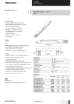
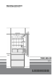
The basicDIM RCL is a digital control device which can be used to operate up to 25 DSI control gear elements
simultaneously in one luminaire group. The luminaires connected to the basicDIM RCL control device can be
daylight-linked using up to four basicDIM sensors.
The system enables lighting to be operated in an energy-saving way by switching the lighting off when nobody
is present. A further advantage of presence control is that the lighting is immediately switched on again as soon
as someone enters the detection range of the basicDIM sensor. Up to 20 basicDIM RCL control devices can be
easily wired together with the Link Line control line. Presence control can then be extended to include up to 20
luminaire groups.
basicDIM RCL overview
13
D2
Max. 25 DSI PCA
tc
Art.-No.: 86458998
T
D1
Made in Switzerland
Light set enabled
Light set disabled
130
www.tridonic.com
N416
• 0 •
• C • E
For Installation, Function selector
and Jumpers, see manual
basicDIM RCL
A
220-240V 50/60Hz
Link Line
• 8 •
4
L
N
• 4 • 6
2
3
2
1
+12V
230V 0,01A
wire preparation:
0,5 - 1,5
8 - 9 mm
LUX
ta: 0 - 60°C
tc: +70C°
PIR
5
6
7
8
GND
1. Power supply (adaptor L, N) 220/230/240 V, 50/60 Hz
2. Digital interface (Link Line) for connecting up to 20 basicDIM RCL control devices
3. Input T for direct connection of conventional 230 V, 50/60 Hz momentary-action switches for smoothly
adjusting the luminaire group
4. Outputs D1 and D2 for one luminaire group
5. Rotary switch for setting functions (presence control, daylight-linked closed-loop control, test)
6. Jumper reserved for future settings. Must always be fitted in order to operate the basicDIM RCL control device
properly
7. Jumper for enabling/disabling configuration
8. Inputs +12V, LUX, PIR and GND for connecting basicDIM sensors
basicDIM RCL Product manual 1.0 | 02.2011 | en 3
English
Introduction
INTRODUCTION
Basic functions
Output for luminaire group
No more than 25 DSI control gear elements can be connected to the output. The DSI control gear elements connected are controlled together.
Input T on the control device
Input T is designed for dimming and brightening the lighting (by holding down the switch). The input can only be
used for single momentary-action switch operation. If the lighting is switched off manually, briefly pressing the
switch recalls the last value set for the luminaire group. Multiple conventional 230 V, 50/60 Hz momentary-action
switches can be connected to the input in parallel.
Inputs PIR and LUX on the control device
Up to four basicDIM sensors can be connected to the PIR and LUX inputs in parallel.
Presence control
The basicDIM RCL control device enables lighting to be controlled by the presence/absence of people. In addition
to the basicDIM RCL control device, basicDIM sensors are also required for this function.
Link Line digital interface
Up to 20 basicDIM RCL control devices can be electrically connected using the interface. Up-to-date presence
control information is transmitted via the Link Line to all basicDIM RCL control devices connected to the digital
interface.
Daylight-linked closed-loop control
The basicDIM RCL control device enables lighting to be regulated by the level of daylight entering the room. In
addition to the basicDIM RCL control device, at least one basicDIM sensor is required for this function.
4 basicDIM RCL Product manual 1.0 | 02.2011 | en
DESCRIPTION OF FUNCTIONS
Description of functions
Dimming
Dimming is the smooth adjustment of the brightness provided by the lighting. The basicDIM RCL control device
enables the user to smoothly adjust the lighting manually at any time.
The most expensive light is a light that is left on in unused rooms and work areas. The basicDIM RCL control
device enables lighting to be operated in an energy-saving way by switching the lighting off when nobody is
present.
A further advantage of presence control is that the lighting is immediately switched on again as soon as someone
enters the detection range of a basicDIM sensor.
2
• C • E
• 0 •
A
• 4 • 6
• 8 •
2
• C • E
• 0 •
• 4 • 6
A
Mode ON/OFF (switch on and off lighting):
If a person enters the detection range of the basicDIM sensor, the lighting is switched
on. If no one is located in the detection range, the lighting is switched off once the runon time has elapsed.
If the momentary-action switch connected to input T is briefly pressed when someone is
present in the range, the lighting is switched off for 15 minutes. If the momentary-action
switch is briefly pressed again, the lighting is switched on to the last set value.
Mode only OFF (switch off lighting):
The lighting is switched on manually. If no one is located in the detection range of the
presence detector, the lighting is switched off once the run-on time has elapsed.
• 8 •
2
• C • E
• 0 •
A
• 4 • 6
• 8 •
2
• C • E
• 0 •
• 4 • 6
A
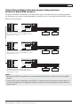
Mode ON/never OFF (switch on the lighting and change to brightness value
10%):
If a person enters the detection range of the presence detector, the lighting is switched
on. If no one is located in the detection range, the lighting is dimmed to a brightness
level of 10% once the run-on time has elapsed. The brightness level is fixed at 10%.
Mode OFF/never OFF (change to brightness value 10%):
The lighting is switched on manually. If no one is located in the detection range, the
lighting is dimmed to a brightness level of 10% once the run-on time has elapsed. The
brightness level is fixed at 10%.
• 8 •
basicDIM RCL Product manual 1.0 | 02.2011 | en 5
English
Presence control
DESCRIPTION OF FUNCTIONS
2
• C • E
• 0 •
Mode no PIR:
Presence control is disabled.
A
• 4 • 6
• 8 •
Notes:
! Mode no PIR: daylight-linked closed-loop control is enabled.
! All presence detectors and motion sensors connected to input PIR function in the operating mode are set on
the basicDIM RCL control device.
! If no basicDIM sensor is connected to input PIR, set the rotary switch to position D or E (mode no PIR).
Presence control via Link Line digital interface
If multiple basicDIM RCL control devices are connected to the Link Line digital interface in parallel, information
that the presence of a person has been detected is transmitted to all basicDIM RCL control devices that are
connected.
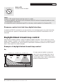
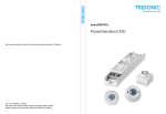
Daylight-linked closed-loop control
Optimal lighting conditions promote a feeling of wellbeing and boost motivation. The best light of all is natural
daylight. However, if daylight is not available in sufficient quantity or quality, it is necessary to supplement it with
artificial light. Throughout the day, the basicDIM RCL control device automatically balances the level of artificial
light in a room against the amount of daylight.
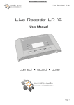
Example of daylight-linked closed-loop control
Day
basicDIM RCL (Grp1) basicDIM RCL (Grp2) basicDIM RCL (Grp3)
Required illuminance
Daylight
Artificial light
6 basicDIM RCL Product manual 1.0 | 02.2011 | en
If a large amount of daylight is entering the
room, the first luminaire group (Grp1) next to
the window is dimmed. The luminaires in the
luminaire groups (Grp2, Grp3) are brightened to
provide the required illuminance.
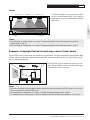
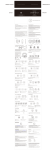
DESCRIPTION OF FUNCTIONS
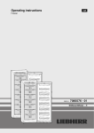
Twilight
basicDIM RCL (Grp1) basicDIM RCL (Grp2) basicDIM RCL (Grp3)
If the level of daylight in the room falls, the luminaires in the other groups (Grp1, Grp2, Grp3) are
brightened as necessary to provide the required
illuminance.
Daylight
English
Required illuminance
Artificial light
Notes:
! F or information on project design see section "Incorporating daylight-linked closed-loop control into the
project design", page 13.
! F or information on configuration see section "Configuring daylight-linked closed-loop control", page 21.
Example of daylight-linked closed-loop control (look down)
The basicDIM sensor is mounted on the ceiling over the workspace. The light reflected from the workspace (both
artificial and natural daylight) is detected by the basicDIM sensor and used to regulate the artificial light to maintain the required illuminance.
basicDIM RCL (Grp1)
basicDIM RCL (Grp2)
basicDIM sensor
basicDIM sensor
One basicDIM sensor is required for each area in the
room. The basicDIM sensor can also be used for presence detection at the same time.
Notes:
! For more information relating to project design, positioning and mounting the basicDIM sensor, see the installation instructions for the basicDIM sensor.
! For information on configuration see section "Daylight-linked closed-loop control", page 6.
! If a daylight-linked luminaire group is adjusted, daylight-linked closed-loop control continues at this value.
basicDIM RCL Product manual 1.0 | 02.2011 | en 7
PROJECT DESIGN
Project design
Recommended procedure
1. Ascertain the customer's needs and requirements
2. Incorporate luminaire groups into the project design
3. Incorporate operation into the project design
4. Incorporate presence detectors into the project design
5. Incorporate daylight-linked closed-loop control into the project design
Incorporating luminaire groups into the project
design
A separate basicDIM RCL control device must be included in the project design for each luminaire group.
Luminaires within a luminaire group cannot be controlled individually.
No more than 25 DSI control gear elements can be connected to the output.
Notes:
!O
nly DSI control gear may be connected to the output of the basicDIM RCL control device.
! A separate basicDIM RCL control device must be included in the project design for each luminaire group. If
multiple luminaire groups are required, it must first be determined which luminaires belong to which luminaire
groups and the cabling must be planned accordingly.
! If daylight-linked closed-loop control is included in the project design, it must be taken into account that each
luminaire group will be controlled individually. When luminaire groups are being incorporated into the project
design, it must be noted that daylight affects the different areas of the room in different ways, see section
"Configuring daylight-linked closed-loop control", page 21. Plan the cabling accordingly.
! If presence control is included in the project design, it must be taken into account that each luminaire group
will be controlled individually. If multiple control devices are connected to each other via the Link Line interface, multiple luminaire groups can be controlled in parallel.
! F or details on the type of cabling (DSI control line) and installation material required, see section "Carrying out
an installation test", page 16.
8 basicDIM RCL Product manual 1.0 | 02.2011 | en
PROJECT DESIGN
Incorporating operation into the project design
Operating individual luminaire groups manually
Daylight-linked closed-loop control mode "OFF": briefly pressing the momentary-action switch alternates
between recalling the value last set for the luminaires (luminaire group) connected to the basicDIM RCL control
device and switching off the luminaires (luminaire group). Holding down the momentary-action switch alternates
between dimming and brightening the luminaires (luminaire group) between 1% and 100%.
Daylight-linked closed-loop control mode "ON": briefly pressing the momentary-action switch alternates
between enabling and disabling daylight-linked closed-loop control. When enabled, the lighting is smoothly adjusted to maintain the required illuminance. Holding down the momentary-action switch alternates between dimming and brightening the luminaires (luminaire group) between 1% and 100%.
Example: operating luminaire groups individually
L
L
N
220-240V 50/60Hz
Link Line
T
D2
L
N
Max. 25 DSI PCA
220-240V 50/60Hz
Link Line
T
D2
L
N
Max. 25 DSI PCA
220-240V 50/60Hz
Link Line
T
Made in Switzerland
D2
Max. 25 DSI PCA
N416
D000 0000 0000000
+12V
8 - 9 mm
LUX
PIR
ta: 0 - 60°C
tc: +70C°
GND
For Installation, Function selector
and Jumpers, see manual
basicDIM RCL
tc
Light set enabled
basicDIM RCL control device: individual operation of luminaire group 2 (Grp 2)
Art.-No.: 86458998
Light set disabled
Made in Switzerland
+12V
230V 0,01A
wire preparation:
0,5 - 1,5
130
www.tridonic.com
N416
D000 0000 0000000
8 - 9 mm
LUX
PIR
ta: 0 - 60°C
tc: +70C°
GND
For Installation, Function selector
and Jumpers, see manual
basicDIM RCL
tc
Light set enabled
basicDIM RCL control device: individual operation of luminaire group 3 (Grp 3)
Art.-No.: 86458998
13
D1
Light set enabled
Light set disabled
230V 0,01A
wire preparation:
0,5 - 1,5
130
www.tridonic.com
13
D1
tc
basicDIM RCL control device: individual operation of luminaire group 1 (Grp 1)
Art.-No.: 86458998
13
D1
For Installation, Function selector
and Jumpers, see manual
basicDIM RCL
Light set disabled
130
www.tridonic.com
Made in Switzerland
N416
D000 0000 0000000
+12V
230V 0,01A
wire preparation:
0,5 - 1,5
8 - 9 mm
LUX
ta: 0 - 60°C
tc: +70C°
PIR
GND
basicDIM RCL Product manual 1.0 | 02.2011 | en 9
English
Conventional 230 V, 50/60 Hz momentary-action switches can be connected to input T on the basicDIM RCL
control device. The momentary-action switch connected to input T functions in the operating mode set by the
rotary switch on the basicDIM RCL control device.
PROJECT DESIGN
Operating multiple luminaire groups manually
Conventional 230 V, 50/60 Hz momentary-action switches can be connected to input T on the basicDIM RCL
control device. One momentary-action switch, connected to the T inputs of the basicDIM RCL control devices
in the system, can be used to operate all luminaires (all luminaire groups) simultaneously. The momentaryaction switch connected to input T functions in the operating mode selected using the rotary switch on the
basicDIM RCL control device.
Daylight-linked closed-loop control mode "OFF": briefly pressing the momentary-action switch alternates
between recalling the value last set for all luminaire groups and switching off all lighting. Holding down the
momentary-action switch alternates between dimming and brightening all lighting (all luminaire groups) between
1% and 100%.
Daylight-linked closed-loop control mode "ON": briefly pressing the momentary-action switch alternates
between enabling and disabling daylight-linked closed-loop control for all basicDIM RCL control devices. When
enabled, all lighting is smoothly adjusted to maintain the required illuminance. Holding down the momentaryaction switch alternates between dimming and brightening all luminaire groups between 1% and 100%.
Example: operating all luminaire groups simultaneously
L
N
220-240V 50/60Hz
Link Line
T
D2
L
N
Max. 25 DSI PCA
220-240V 50/60Hz
Link Line
T
D2
L
N
L
Max. 25 DSI PCA
220-240V 50/60Hz
Link Line
T
Made in Switzerland
D2
Max. 25 DSI PCA
N416
D000 0000 0000000
8 - 9 mm
+12V
LUX
PIR
ta: 0 - 60°C
tc: +70C°
GND
For Installation, Function selector
and Jumpers, see manual
basicDIM RCL
tc
Light set enabled
basicDIM RCL control device: luminaire group 2 (Grp 2).
Art.-No.: 86458998
Light set disabled
230V 0,01A
wire preparation:
0,5 - 1,5
130
www.tridonic.com
Made in Switzerland
N416
D000 0000 0000000
8 - 9 mm
+12V
LUX
PIR
ta: 0 - 60°C
tc: +70C°
GND
For Installation, Function selector
and Jumpers, see manual
basicDIM RCL
tc
Light set enabled
basicDIM RCL control device: luminaire group 3 (Grp 3).
Art.-No.: 86458998
13
D1
Light set enabled
Light set disabled
230V 0,01A
wire preparation:
0,5 - 1,5
130
www.tridonic.com
13
D1
tc
Art.-No.: 86458998
13
D1
For Installation, Function selector
and Jumpers, see manual
basicDIM RCL
basicDIM RCL control device: luminaire group 1 (Grp 1).
Light set disabled
130
www.tridonic.com
Made in Switzerland
N416
D000 0000 0000000
230V 0,01A
wire preparation:
0,5 - 1,5
8 - 9 mm
ta: 0 - 60°C
tc: +70C°
+12V
LUX
PIR
GND
Notes:
! A ny number of momentary-action switches can be connected to input T on the basicDIM RCL control device
in parallel.
! T he phase (L) adjacent to the inputs does not have to be the same as the phase used to supply power to the
basicDIM RCL control device. However, only phases assigned to the same sub-circuit may be connected.
10 basicDIM RCL Product manual 1.0 | 02.2011 | en
PROJECT DESIGN
Incorporating presence detectors (basicDIM
sensor) into the project design
Controlling individual luminaire groups using presence
detectors (basicDIM sensor)
English
The basicDIM sensor controls the luminaire group connected to the basicDIM RCL control device.
Input PIR
• C • E
• 0 •
A
• 4 • 6
• 8 •
Light set enabled
2
or Installation, Function selector
nd Jumpers, see manual
Light set disabled
230V 0,01A
wire preparation:
0,5 - 1,5
8 - 9 mm
+12V
LUX
PIR
ta: 0 - 60°C
tc: +70C° GND
basicDIM sensor
basicDIM sensor
Notes:
! U p to four basicDIM sensors can be connected to each basicDIM RCL control device in parallel.
! T he basicDIM sensors 5DP 19f, 5DP 41rc and 5DP 41rs can be connected in parallel.
! In the project design, position the basicDIM sensor so that it is located above the workspace.
! R eception characteristics are changed by reflections on the walls, furniture or floor.
! T he detection ranges of several basicDIM sensors installed close to each other can overlap.
! A void sources of heat within the detection range (e.g. printers, copiers, fax machines).
! F or information regarding project design, installation materials (cable), and positioning and mounting the
basicDIM sensor, consult the data sheet for the basicDIM sensor.
basicDIM RCL Product manual 1.0 | 02.2011 | en 11
PROJECT DESIGN
Controlling multiple luminaire groups using presence
detectors (basicDIM sensors)
If multiple basicDIM RCL control devices are connected by the Link Line digital interface in parallel, information
that the presence of a person has been detected by a basicDIM sensor is transmitted to all basicDIM RCL control
devices that are connected.
• C • E
A
tc
Art.-No.:Light
86458998
set disabled
T
D2
For Installation, Function selector
and Jumpers, see manual
basicDIM
RCL
Light set
enabled
• 8 •
tc
Link Line
D1
• 0 •
For Installation, Function selector
and Jumpers, see manual
230V 0,01A
130
13
wire preparation:
0,5 - 1,5
• 4 • 6
220-240V 50/60Hz
2
L
N
230V 0,01A
wire preparation:
0,5 - 1,5
LUX
PIR
N416
www.tridonic.com
ta: 0 - 60°C
GND0000 0000000
tc: +70C° D000
8 -Made
9 mm in Switzerland
Max. 25 DSI PCA
Light set enabled
Light set disabled
+12V
8 - 9 mm
+12V
LUX
PIR
ta: 0 - 60°C
tc: +70C°
GND
basicDIM RCL control device: luminaire group 1 (Grp 1).
The connected presence detectors (basicDIM sensor) control
luminaire groups 1, 2 and 3.
tc
T
D1
D2
• 0 •
• C • E
For Installation, Function selector
and Jumpers, see manual
A
basicDIM RCL
• 8 •
Link Line
For Installation, Function selector
and Jumpers, see manual
• 4 • 6
220-240V 50/60Hz
tc
Light set enabled
Art.-No.:Light
86458998
set disabled
Light set enabled
Light set disabled
+12V
230V 0,01A 130
13
wire preparation:
LUX
0,5 - 1,5
N416
PIR
www.tridonic.com
ta: 0 - 60°C
GND0000 0000000
tc: +70C° D000
8 -Made
9 mm in Switzerland
Max. 25 DSI PCA
230V 0,01A
wire preparation:
0,5 - 1,5
8 - 9 mm
+12V
LUX
PIR
ta: 0 - 60°C
tc: +70C°
GND
basicDIM RCL control device: luminaire group 2 (Grp 2).
The connected presence detectors (basicDIM sensor) control
luminaire groups 1, 2 and 3.
T
D1
D2
Max. 25 DSI PCA
tc
• 0 •
• C • E
For Installation, Function selector
and Jumpers, see manual
Art.-No.:Light
86458998
set disabled
+12V
230V 0,01A 130
13
wire preparation:
LUX
0,5 - 1,5
N416
PIR
www.tridonic.com
ta: 0 - 60°C
GND0000 0000000
tc: +70C° D000
8 -Made
9 mm in Switzerland
A
basicDIM
RCL
Light set enabled
• 8 •
Link Line
For Installation, Function selector
and Jumpers, see manual
basicDIM sensor
• 4 • 6
220-240V 50/60Hz
basicDIM sensor
2
L
N
basicDIM sensor
2
L
N
basicDIM sensor
tc
Light set enabled
Light set disabled
230V 0,01A
wire preparation:
0,5 - 1,5
8 - 9 mm
basicDIM RCL control device: luminaire group 3 (Grp 3).
The connected presence detectors (basicDIM sensor) control
luminaire groups 1, 2 and 3.
ta: 0 - 60°C
tc: +70C°
+12V
LUX
PIR
GND
basicDIM sensor
basicDIM sensor
Notes:
! U p to 20 basicDIM RCL control devices can be connected by wiring them in parallel to the Link Line digital
interface.
! T he basicDIM sensors connected to the basicDIM RCL control device only control other luminaire groups via
the Link Line control line if the lighting was previously switched on using the momentary-action switch connected to input T.
12 basicDIM RCL Product manual 1.0 | 02.2011 | en
PROJECT DESIGN
Incorporating daylight-linked closed-loop control
into the project design
In addition to the basicDIM RCL control device, a basicDIM sensor is required for daylight-linked closed-loop control. The basicDIM sensor detects both artificial and natural light reflected from the workspace.
Input LUX
English
• C • E
• 0 •
A
• 8 •
Light set enabled
• 4 • 6
tc
2
For Installation, Function selector
and Jumpers, see manual
Light set disabled
N416
+12V
230V 0,01A
wire preparation:
0,5 - 1,5
8 - 9 mm
LUX
ta: 0 - 60°C
tc: +70C°
PIR
GND
basicDIM sensor
basicDIM sensor
Notes:
! U p to four basicDIM sensors can be connected to each basicDIM RCL control device in parallel.
! F or information regarding project design, and positioning and mounting the basicDIM sensor, see the installation instructions for the basicDIM sensor.
! T he basicDIM sensors 5DP 19f, 5DP 41rc and 5DP 41rs can be connected in parallel.
Working range for daylight-linked closed-loop control
basicDIM RCL (Grp1)
basicDIM RCL (Grp2)
basicDIM sensor
basicDIM RCL (Grp1)
basicDIM RCL (Grp2)
basicDIM sensor
basicDIM sensor
basicDIM sensor
Notes:
! Only the luminaires illuminating a workspace monitored by a basicDIM sensor should be regulated using
daylight-linked closed-loop control. Adjacent luminaires that are regulated via a second sensor should not
illuminate the workspace monitored by the first sensor, in order to enable efficient daylight-linked closed-loop
control.
! Daylight-linked closed-loop control relies on the measurement of the artificial and natural daylight reflected
from a workspace. This measuring procedure does not give exact data for the actual illuminance on the
workspace.
! Daylight-linked closed-loop control deliberately reacts to changes in the daylight levels slowly in order for
these reactions to be perceived as little as possible.
basicDIM RCL Product manual 1.0 | 02.2011 | en 13
I N S TA L L AT I O N
Installation
DSI control lines, Link Line control line
The DSI control lines can be laid together with a 230 V AC power supply line, provided that it is sufficiently insulated (2 x basic insulation). The control lines can consist of conventional installation material and do not have to
be braided or shielded. When selecting the control line, ensure that the maximum resistance is 8 ohm per 300 m
length of control line.
The installation material must be approved for low-voltage installation up to 1000 V (DIN VDE 0472, Part 508).
e. g. H05V V-U 2 x 0.75 mm2
H05V V-U 2 x 1.50 mm2
Insulation of DSI interfaces
The insulation of the digital interfaces meets the requirements for basic insulation and was tested in
accordance with EN 60928. There is no guarantee of compliance with SELV standards.
Line cross-sections and lengths
DSI control line:
Line cross-section
2 x 0.50 mm2
2 x 0.75 mm2
2 x 1.00 mm2
2 x 1.50 mm2
Maximum line length
125 m
125 m
125 m
250 m
Link Line control line:
Line cross-section
1 x 0.50 mm2
1 x 0.75 mm2
2
1 x 1.00inmm
tree structure
1 x 1.50 mm2
Maximum line length
125 m
125 m
125 m
250 m
Wiring topology
in tree structure
The following topologies may be used for DSI wiring:
in star structure
in line structure
in tree structure
in star structure
Notes:
! E very output on the basicDIM RCL controlindevice
must be wired separately. The outputs cannot be connected
line structure
to each other electrically.
! R ing topologies are not permitted.
in star structure
14 basicDIM
in line RCL
structure Product manual 1.0 | 02.2011 | en
I N S TA L L AT I O N
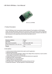
Wiring diagram
Netz/
Mains/
Réseau/ L
Rete/ N
Red/ PE
Net
220 - 240 V AC
50/60 Hz
max. 4 Sensoren basicDIM Sensor
D1
D2
PE
N
L
PCA
max. 25 Lampenbetriebsgeräte (PCA, TE, ...)
max. 25 lamp control ballasts (PCA, TE, ...)
25 ballasts maximum (PCA,TE, ...)
max. 25 reattori (PCA, TE, ...)
máx. 25 dispositivos de control de lámparas (PCA, TE, ...)
max. 25 hulpapparaten voor lampen (PCA, TE, ...)
D1
D2
PE
N
L
English
+12 V
LUX
PIR
GND
PCA
basicDIM RCL
D1
D2
PE
N
L
T
D1
D2
PCA
L
N
basicDIM RCL Product manual 1.0 | 02.2011 | en 15
I N S TA L L AT I O N
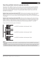
Carrying out an installation test
Carry out the installation test once electrical installation has been completed in full and tested.
Set the rotary switch on the basicDIM RCL control device to position F for the installation test.
Overview
What is tested?
Output
Input T
Presence control
Daylight-linked closedloop control
How is it tested?
What happens if the installation
is OK?
Hold down the momentary-action
All connected luminaires brighten or
switch connected to input T.
dim.
Hold down the momentary-action
All connected luminaires brighten or
switch connected to input T.
dim.
Set rotary switch on basicDIM RCL
If a person enters the detection range
control device to position F (presence of the basicDIM sensor, the lighting is
control mode: ON/OFF; run-on time: switched on. After the person exits the
15 seconds).
detection range, the lighting switches
off in 15 seconds.
Set the rotary switch on the
When the basicDIM sensor is covered,
basicDIM RCL control device to posi- the lighting slowly brightens.
tion F (daylight-linked closed-loop
When the basicDIM sensor is illumicontrol mode: ON; status: manual).
nated, the lighting slowly dims.
Note: Daylight-linked dimming/brightening may take several minutes.
Interrupting the power supply on the basicDIM RCL control
device
•D
aylight-linked closed-loop control was disabled before power supply was interrupted (mode OFF):
After power supply is restored, value is first output as 1% brightness (10% if mode OFF/never OFF is enabled).
Then the value (brightness) that was enabled before the power supply was interrupted is output.
•D
aylight-linked closed-loop control was enabled before power supply was interrupted (mode ON):
After power supply is restored, value is first output as 1% brightness (10% if mode OFF/never OFF is enabled).
Then the value (brightness) that is currently being calculated via daylight-linked closed-loop control is output.
Note:
! If the lighting was switched off before the power supply to the basicDIM RCL control device was interrupted,
the connected luminaires will go to a value of 0% when the power supply is restored.
16 basicDIM RCL Product manual 1.0 | 02.2011 | en
C O N F I G U R AT I O N
Configuration
Before beginning configuration, carry out an installation test (see section "Carrying out an installation test",
page 16).
The basicDIM RCL control device provides a range of functions. Determine which function is desired and use a
screwdriver to configure that function on the rotary switch on the basicDIM RCL control device (see section
"Description of functions", page 5).
2
• C • E
• 0 •
A
• 4 • 6
• 8 •
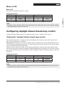
Configurable functions
Position
0
1
2
3
4
5
6
7
8
9
A
B
C
D
E
F
Presence control
Mode
Run-on time
ON/OFF
20 min
ON/OFF
20 min
ON/OFF
30 min
ON/OFF
40 min
ON/OFF
adaptive
ON/never OFF
20 min
ON/OFF
adaptive
ON/OFF
20 min
only OFF
10 min
only OFF
20 min
only OFF
30 min
OFF/never OFF
20 min
only OFF
20 min
no PIR
--no PIR
--Test
ON/OFF
15 sec
Daylight-linked closed-loop control
Mode
Status
ON
manual
ON
automatic
ON
manual
ON
manual
ON
manual
ON
manual
OFF
--OFF
--ON
manual
ON
manual
ON
manual
ON
manual
OFF
--ON
manual
ON
automatic
ON
manual
Note:
! T he rotary switch is not only used to set the mode for presence control, but also to set the mode for daylightlinked closed-loop control at the same time.
basicDIM RCL Product manual 1.0 | 02.2011 | en 17
English
Configuring functions
C O N F I G U R AT I O N
Setting illuminance
Different tasks call for different required illuminance levels (see section "Extract of required illuminance according to EN 12464", page 29). The basicDIM RCL control device can be used to recall a lighting scene and
configure it individually.
Setting illuminance and recalling the set value (without daylightlinked closed-loop control)
The output can be smoothly adjusted to achieve the required illuminance (lx) using the momentary-action switch
connected to input T. The basicDIM RCL control device records the set value.
Briefly pressing the momentary-action switch or entering the detection range of the presence detector recalls the
last set value. Briefly pressing the momentary-action switch again or leaving the detection range of the presence
detector switches off the lighting.
To enable the "Set illuminance and recall set value (without daylight-linked closed-loop control)" function, select
one of the following settings and configure it on the rotary switch.
Configurable functions
Position
6
7
C
Presence control
Mode
Run-on time
ON/OFF
adaptive
ON/OFF
20 min
only OFF
20 min
Daylight-linked closed-loop control
Mode
Status
OFF
--OFF
--OFF
---
Note:
! T he rotary switch is not only used to set the mode for presence control, but also to set the mode for daylightlinked closed-loop control at the same time.
Configuring presence control
Configure the desired presence control function using the rotary switch on the basicDIM RCL control device.
Mode ON/OFF (recall lighting scene and switch off lighting)
Mode ON/OFF
(see section "Description of functions", page 5)
Run-on times for mode ON/OFF
The run-on time can be fixed or adaptive as required. If the run-on time is set to "adaptive", the system differentiates between times when people rarely enter the detection range of the presence detector, and times when the
range is quite active. The duration of the run-on time (between 4 min and 20 min) is then adapted via presence
control to suit the situation.
18 basicDIM RCL Product manual 1.0 | 02.2011 | en
C O N F I G U R AT I O N
Configurable functions
Position
0
1
2
3
4
6
7
Presence control
Mode
Run-on time
ON/OFF
20 min
ON/OFF
20 min
ON/OFF
30 min
ON/OFF
40 min
ON/OFF
adaptive
ON/OFF
adaptive
ON/OFF
20 min
Daylight-linked closed-loop control
Mode
Status
ON
manual
ON
automatic
ON
manual
ON
manual
ON
manual
OFF
--OFF
---
Note:
! T he rotary switch is not only used to set the mode for presence control, but also to set the mode for daylightlinked closed-loop control at the same time.
Mode only OFF (switch off lighting)
Mode only OFF
(see section "Description of functions", page 5)
Run-on times for mode only OFF
The run-on times are fixed.
Available settings: 10 min, 20 min, 30 min.
Configurable functions
Position
8
9
A
C
Presence control
Mode
Run-on time
only OFF
10 min
only OFF
20 min
only OFF
30 min
only OFF
20 min
Daylight-linked closed-loop control
Mode
Status
ON
manual
ON
manual
ON
manual
OFF
---
Note:
! T he rotary switch is not only used to set the mode for presence control, but also to set the mode for daylightlinked closed-loop control at the same time.
basicDIM RCL Product manual 1.0 | 02.2011 | en 19
English
Available settings: 20 min, 30 min, 40 min, adaptive (between 4 min and 20 min).
C O N F I G U R AT I O N
Mode ON/never OFF (switch on the lighting and change to
brightness value 10%)
Mode ON/never OFF
(see section "Description of functions", page 5)
Run-on times for mode ON/never OFF
The run-on time is fixed at 20 min.
Configurable functions
Position
5
Presence control
Mode
Run-on time
ON/never OFF
20 min
Daylight-linked closed-loop control
Mode
Status
ON
manual
Note:
! T he rotary switch is not only used to set the mode for presence control, but also to set the mode for daylightlinked closed-loop control at the same time.
Mode OFF/never OFF (change to brightness value 10%)
Mode OFF/never OFF
(see section "Description of functions", page 5)
Run-on times for mode OFF/never OFF
The run-on time is fixed at 20 min.
Configurable functions
Position
B
Presence control
Mode
Run-on time
OFF/never OFF
20 min
Daylight-linked closed-loop control
Mode
Status
ON
manual
Note:
! T he rotary switch is not only used to set the mode for presence control, but also to set the mode for daylightlinked closed-loop control at the same time.
20 basicDIM RCL Product manual 1.0 | 02.2011 | en
C O N F I G U R AT I O N
Mode no PIR
Mode no PIR
(see section "Description of functions", page 5)
D
E
Presence control
Mode
Run-on time
no PIR
--no PIR
---
Daylight-linked closed-loop control
Mode
Status
ON
manual
ON
automatic
Note:
! T he rotary switch is not only used to set the mode for presence control, but also to set the mode for daylightlinked closed-loop control at the same time.
Configuring daylight-linked closed-loop control
Daylight-linked closed-loop control has two operating modes (status): "automatic" and "manual".
"Automatic" daylight-linked closed-loop control
Every time the illuminance is changed manually by holding down the momentary-action switch connected to
input T, the ideal illuminance is changed.
Holding down the momentary-action switch smoothly adjusts the lighting to achieve the required illuminance (lx).
The basicDIM RCL control device records this set value automatically and then considers it to be the ideal illuminance for daylight-linked closed-loop control.
Briefly pressing the momentary-action switch or entering the detection range of the presence detector causes
the value currently being calculated via daylight-linked closed-loop control to be output at the luminaires. Briefly
pressing the momentary-action switch again or leaving the detection range of the presence detector switches off
the lighting.
Configurable functions
Position
1
E
Presence control
Mode
Run-on time
ON/OFF
20 min
no PIR
---
Daylight-linked closed-loop control
Mode
Status
ON
automatic
ON
automatic
Note:
! T he rotary switch is not only used to set the mode for daylight-linked closed-loop control, but also to set the
mode for presence control at the same time.
basicDIM RCL Product manual 1.0 | 02.2011 | en 21
English
Configurable functions
Position
C O N F I G U R AT I O N
Setting and saving the ideal illuminance
The ideal illuminance is set by holding down the momentary-action switch connected to input T.
1. Switch on the lighting by briefly pressing the momentary-action switch.
2. Smoothly adjust the lighting to achieve the desired illuminance (lx) by holding down the momentary-action
switch.
3. Save the current illuminance (lx) as the ideal illuminance by releasing the momentary-action switch.
"Manual" daylight-linked closed-loop control
Every time the illuminance (lx) is changed manually by holding down the momentary-action switch connected to
input T, daylight-linked closed-loop control is disabled.
Holding down the momentary-action switch smoothly adjusts the lighting to achieve the desired illuminance (lx).
When the illuminance is changed, daylight-linked closed-loop control is disabled until the momentary-action
switch is briefly pressed or the lighting is switched on/off via presence control.
Configurable functions
Position
0
2
3
4
5
8
9
A
B
D
Presence control
Mode
Run-on time
ON/OFF
20 min
ON/OFF
30 min
ON/OFF
40 min
ON/OFF
adaptive
ON/never OFF
20 min
only OFF
10 min
only OFF
20 min
only OFF
30 min
ON/never OFF
20 min
no PIR
---
Daylight-linked closed-loop control
Mode
Status
ON
manual
ON
manual
ON
manual
ON
manual
ON
manual
ON
manual
ON
manual
ON
manual
ON
manual
ON
manual
Note:
! T he rotary switch is not only used to set the mode for daylight-linked closed-loop control, but also to set the
mode for presence control at the same time.
22 basicDIM RCL Product manual 1.0 | 02.2011 | en
C O N F I G U R AT I O N
Enabling and disabling configuration of the ideal illuminance
Configuration must be enabled in order to set the ideal illuminance. Insert the "Light set" jumper into the
basicDIM RCL control device to enable configuration.
Enable:
• C • E
• 8 •
Light set enabled
Enabling configuration: jumper is fitted.
Light set disabled
230V 0,01A
wire preparation:
0,5 - 1,5
N416
D000 0000 0000000
8 - 9 mm
+12V
LUX
PIR
ta: 0 - 60°C
tc: +70C°
GND
Disable:
• C • E
A
• 4 • 6
• 8 •
tc
• 0 •
2
For Installation, Function selector
and Jumpers, see manual
Light set enabled
Disabling configuration: jumper is not fitted.
Light set disabled
230V 0,01A
wire preparation:
0,5 - 1,5
N416
D000 0000 0000000
8 - 9 mm
ta: 0 - 60°C
tc: +70C°
+12V
LUX
PIR
GND
Note:
! E nabling and disabling configuration is only possible in "manual" operating mode (status).
Setting the ideal illuminance
The ideal illuminance is set when the lowest illuminance in operation occurs in the workspace. Darken the room
by closing the blinds, curtains, etc. If it is impossible to darken the room artificially, set the ideal illuminance in
the evening or at night.
1. Place a luxmeter on the work surface (e.g. desk) situated under the luminaire group.
2. Use the momentary-action switch to smoothly adjust the lighting until the ideal illuminance is reached. This
can be seen on the luxmeter.
3. Wait approx. 40 seconds.
4. Compare the illuminance on the luxmeter with the desired ideal illuminance. Repeat steps 2 and 3 if there is
any deviation.
Saving the ideal illuminance
1. Briefly press the momentary-action switch connected to input T twice.
2. The connected luminaires blink twice to confirm that the ideal illuminance has been successfully saved.
basicDIM RCL Product manual 1.0 | 02.2011 | en 23
English
A
• 4 • 6
tc
• 0 •
2
For Installation, Function selector
and Jumpers, see manual
C O N F I G U R AT I O N
Setting the ideal illuminance using the light/dark procedure of a
basicDIM sensor
If the "Light set" jumper is not or cannot be fitted on the basicDIM RCL control device for setting the ideal illuminance (e.g. because the basicDIM RCL control device is installed somewhere difficult to access, such as in a
luminaire or in a suspended ceiling), the ideal illuminance can alternatively be set using the light/dark procedure
of a basicDIM sensor.
Enabling configuration of the ideal illuminance
Configuration must first be enabled in order to set the ideal illuminance. Carry out a light/dark procedure using a
basicDIM sensor connected to the basicDIM RCL control device to enable configuration.
Enable:
1. Brighten the luminaires to 100%.
2. Shine a bright torch on the basicDIM sensor three times at intervals of approximately one second (light/dark
procedure).
3. The connected luminaires blink once to confirm that the light/dark procedure was successful.
4. Briefly press the momentary-action switch twice ("double-click") within 60 seconds.
5. The connected luminaires blink once to confirm that configuration has been successfully enabled.
Setting the ideal illuminance
The ideal illuminance is set when the lowest illuminance in operation occurs in the workspace. Darken the room
by closing the blinds, curtains, etc. If it is impossible to darken the room artificially, set the ideal illuminance in
the evening or at night.
1. Place a luxmeter on the work surface (e.g. desk) situated under the luminaire group.
2. Use the momentary-action switch to smoothly adjust the lighting until the ideal illuminance is reached. This
can be seen on the luxmeter.
3. Wait approx. 40 seconds.
4. Compare the illuminance on the luxmeter with the desired ideal illuminance. Repeat steps 2 and 3 if there is
any deviation.
Saving the ideal illuminance
1. Briefly press the momentary-action switch connected to input T twice.
2. The connected luminaires blink twice to confirm that the ideal illuminance has been successfully saved.
Disabling configuration of the ideal illuminance
1. Briefly press the momentary-action switch connected to input T.
2. The lighting switches off.
Notes:
! T he brightness values detected by the basicDIM sensors are processed by the basicDIM RCL control device
and used for daylight-linked closed-loop control.
! T he basicDIM sensors should not be covered to set the ideal illuminance.
!C
hanges to workspaces or in the surrounding area (e.g. turning pages of a newspaper) can cause deviations
from the set ideal illuminance.
!M
ake sure that the same lighting conditions in the room (darkening) exist for all basicDIM sensors during
configuration (daylight-linked closed-loop control).
!M
ake sure that no artificial or natural daylight reaches the lens of the basicDIM sensor directly.
24 basicDIM RCL Product manual 1.0 | 02.2011 | en
C O N F I G U R AT I O N
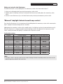
Daylight-linked dimming off and on (Bright-Out/Bright-In)
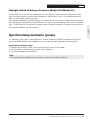
Synchronising luminaire groups
If a momentary-action switch is connected to the T inputs of multiple basicDIM RCL control devices, the luminaires may exhibit different levels of brightness after a number of smooth adjustments have been made.
Synchronising luminaire groups
1. Hold down the momentary-action switch connected to the T inputs for 20 seconds.
2. After 20 seconds, all luminaire groups switch to 50% brightness.
3. The luminaire groups are synchronised.
Note:
! After synchronisation, holding down the momentary-action switch will dim the lighting.
basicDIM RCL Product manual 1.0 | 02.2011 | en 25
English
The basicDIM RCL control device is configured so that if the lighting is switched on and a large amount of daylight is entering the room, the artificial light is dimmed off, and then later, if there is less daylight entering the
room, the artificial light is dimmed on again.
If the lighting is dimmed off via daylight linking, it will remain off even if a presence is detected via presence control. If the lighting is dimmed off via daylight linking, it will switch on if the momentary-action switch connected to
input T is briefly pressed. The lighting is dimmed off again via daylight linking after 10 minutes have passed and
if the daylight conditions have not changed.
C O N F I G U R AT I O N
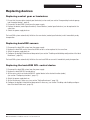
Replacing devices
Replacing control gear or luminaires
1. Ensure that the new device (control gear/luminaire) can be used (see section "Incorporating luminaire groups
into the project design", page 8).
2. Disconnect the basicDIM system from the power supply.
3. Replace the device (control gear/luminaire). Several devices (control gear/luminaires) can be replaced at the
same time.
4. Switch the power supply back on.
The basicDIM system automatically initialises the new device (control gear/luminaire) and is immediately ready
for operation.
Replacing basicDIM sensors
1. Disconnect the basicDIM system from the power supply.
2. Replace the basicDIM sensor. Several basicDIM sensors can be replaced at the same time.
3. Switch the power supply back on.
4. Configure the daylight-linked closed-loop control (see section "Enabling and disabling configuration of the ideal
illuminance", page 23)
The basicDIM system automatically initialises the new basicDIM sensor and is immediately ready for operation.
Replacing the basicDIM RCL control device
1. Disconnect the basicDIM system from the power supply.
2. Replace the basicDIM RCL control device.
3. Set the rotary switch on the basicDIM RCL control device to the desired function (mode)
(see section "Configuring functions", page 17).
4. Switch the power supply back on.
5. Set the illuminance if necessary (see section "Setting illuminance", page 18).
6. Configure the daylight-linked closed-loop control if necessary (see section "Enabling and disabling configuration of the ideal illuminance", page 23)
26 basicDIM RCL Product manual 1.0 | 02.2011 | en
T E C H N I C A L D ATA
Nominal voltage . . . . . . . . . . . 220/230/240 V AC, 50/60 Hz
Permitted input voltage . . . . . . . 198–264 V AC, 50–60 Hz
Power loss . . . . . . . . . . . . . < 1.5 W
Outputs . . . . . . . . . . . . . . . D1, D2, DSI control line
Capacity . . . . . . . . . . . . . . Max. 25 DSI-compatible control gear elements
DSI signal . . . . . . . . . . . . . . 12 V (Manchester Code)
DSI control line . . . . . . . . . . . NYM 2 x 1.5 mm2 (H05VV-U 2 x 1.5 mm2)
Mains line . . . . . . . . . . . . . . NYM 2 x 1.5 mm2 (H05VV-U 2 x 1.5 mm2)
Terminals . . . . . . . . . . . . . . 0.75–2.5 mm2
Housing material . . . . . . . . . . Flame-retardant polycarbonate; halogen-free
Weight . . . . . . . . . . . . . . . approx. 350 g
Permitted ambient temp. . . . . . . . 0 to 60°C
Storage temperature . . . . . . . . . -25 to 55°C
Protection type . . . . . . . . . . . IP20
Line length . . . . . . . . . . . . . DSI control line:
Line cross-section
Maximum line length
2 x 0.50 mm2
125 m
2 x 0.75 mm
2
125 m
2 x 1.00 mm2
125 m
2 x 1.50 mm
250 m
2
Conformity:
EN 61547 Equipment for general lighting purposes. EMC immunity requirements
EN 61347-1 Lamp controlgear (General and safety requirements)
EN 61347-2-11 Lamp controlgear (Particular requirements for miscellaneous electronic circuits used with
luminaires)
EN 55015 Limits and methods of measurement of radio disturbance characteristics of electrical lighting and
similar equipment
ICE 60695-2-11 Fire hazard testing. Test methods. Glowing/hot-wire based test methods. Glow-wire flammability
test method for end-products

13
basicDIM RCL Product manual 1.0 | 02.2011 | en 27
English
Technical data
APPENDIX
Frequently asked questions
How many luminaires (control gear elements) can I connect to one output?
• A maximum of 25 DSI control gear elements can be connected.
How can I connect more than 25 DSI loads to one output?
• Use the DSI-V/T amplifier (art. no. 86458690) to connect up to 50 additional control gear elements.
I have luminaires with both DALI and DSI control gear. Can I run both control gear types from one
basicDIM RCL control device?
• No. Only DSI control gear may be connected.
How many sensors can be connected to a basicDIM RCL control device?
• A maximum of four basicDIM sensors may be connected.
Can I assign one presence detector (basicDIM sensor) to multiple luminaire groups (basicDIM RCL
control devices)?
• Yes. If multiple basicDIM RCL control devices are connected to the Link Line digital interface in parallel, information that the presence of a person has been detected is transmitted to all basicDIM RCL control devices that
are connected.
What components do I have to reconfigure when replacing a basicDIM RCL control device?
• see section "Replacing the basicDIM RCL control device", page 26
Are the current user settings saved if the power is interrupted?
• Yes. When power is restored, the settings that were active before the power supply was interrupted are
recalled.
28 basicDIM RCL Product manual 1.0 | 02.2011 | en
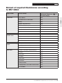
APPENDIX
Type of room
Task or activity
Maintained illuminance [ ] in
the task area [lx]
Office work
Filing, copying
300
Circulation areas in work rooms
300
Writing
500
Reading, data processing
500
CAD workstations
500
Conference and meeting rooms
500
Reception desks
300
Archives
200
Entrance halls
100
Cloakrooms
200
Waiting rooms
200
Cash desks and counters
300
Drawing rooms
500
Drawing rooms in art colleges
750
Technical drawing rooms
750
Stairwells, escalators, moving walkways
150
Canteens
200
Buffet areas
300
Staffrooms
100
Gymnasiums
300
Kitchenettes
200
Catering kitchens
500
Changing rooms, wash rooms and restrooms
200
First-aid rooms
500
Public areas, service
counter areas
Design and drawing
rooms
Side rooms
basicDIM RCL Product manual 1.0 | 02.2011 | en 29
English
Extract of required illuminance according
to EN 12464
APPENDIX
Disposal
CE conformity
For disposal in accordance with the WEEE
Directive:
• Return the device to Tridonic or dispose
of the device in accordance with national
regulations.
• Do not dispose of the device in nonrecyclable waste.
• Do not burn the device.
Tridonic hereby declares that the basicDIM RCL
complies with the relevant EU Directives.
Glossary
Control gear
An electrical device used to operate a lamp. Includes electronic ballasts, smoothly adjustable electronic ballasts,
DSI-compatible electronic ballasts, transformers, phase dimmers, switching actuators, etc.
Illuminance in lux (lx)
Illuminance describes the amount of luminous flux falling on a surface.
DSI
Digital Serial Interface. A standardised interface for digitally operating control gear.
DSI load
A DSI load is a DSI-compatible lamp control gear such as an electronic ballast or electronic transformer. Usually,
lamp control gear counts as one DSI load. See the technical data for further information.
Wiring topology
Types and options for laying the DSI control line (star, linear and/or tree topologies).
Luminaire group
A group of luminaires that can be jointly controlled.
30 basicDIM RCL Product manual 1.0 | 02.2011 | en
Go to www.tridonic.com to find your personal contact at Tridonic.
Art. no. 24166467 01/2011
We reserve the right to make technical changes without notice.
Please contact your local sales office for further information.