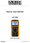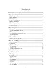
1
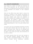
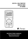
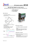
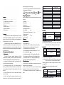
VICTOR 88C User’s Manual for VICTOR 88C Digital Multimeter device has range protection functions. 1-5. Never input current higher than 20A when measuring current; 1-6. Introduction for safety sign “ “ Dangerous voltage existing; “ isolation; “ ” Earthing; “ ” Double ” Shall refer to the user’s manual; ” ” Low battery. III. Unpacking inspection Contents Open the package to check if all parts and accessories are all right I. Summary ………………………………………… in the box II. For purchasers of this multimeter …………… 1. Multimeter III. Unpacking inspection ………………………… 2. Battery (9V) IV. Features ……………………………………… 3. Leather case V. Operation method …………………………… 4. Vibration proof sheath VI. Device maintenance ………………………… 5. Acceptance certificate VII. Trouble shoot ………………………………… 6. Crocodile clip 1 1 1 1 1 1 pair 7. Temperature probe (banana type) I. Summary VICTOR 88C ▲ ▲ ▲ ▲ ▲ ▲ ▲ ▲ ▲ ▲ ▲ ▲ ▲ ▲ 2-3-1. DCV 1 pair Accuracy Resolution 100uV 1mV 10mV 100mV 1V 9. Pencil (20A) 1 pair multimeter with high reliability. It adopts LCD screen with character 10. User’s manual 1 height of 28mm; with functions including unit sign/backlight and IV. Features overload protection, it is easy to use. 1. General features 1-1. Display mode: LCD; Over load protection: 250V DC or 205 V AC peak value for range This series of device can be used to measure DCV, ACV, DC, 1 Range 200mV 2V ±(0.5%+3) 20V 200V 1000V ±(1.0%+5) Input impedance: All range is10MΩ; This series product is a stable and battery-driven 3 1/2 digital 8. Testing accessory Model Function DCV ACV DCA ACA Resistance Ω Diode/ Open circuit Triode hFE Capacitance C Temperature ℃ Frequency f Inductance L Auto power off Backlight Peak value holding 2-3. Technical index AC, resistance, capacitance, inductance, diode, triode, open circuit, 1-2. Max display: 1999 (3 1/2) digits automatic polarity display; temperature and frequency, as well as hold peak value. As an 1-3. Measurement method: double integral A/D conversion; instrument with excellent performance it adopts double integral A/D 1-4. Sampling rate: about 3 time per second; converter as its core. 1-5. Over-range display: the highest digit displays “OL” or “-OL” II. For purchasers of this multimeter 1-6. Low voltage display:” ”; 1. Safety notice 1-7. Working environment: (0~40)℃, relative humidity: <80%; This series of device is designed according to IEC1010 1-8. Power supply: one 9V battery (6F22 or equivalent model); standard (safety standard issued by International Electrotechnical 1-9. Dimension: 189mm * 97mm * 35mm (length*width*height); Committee). Please read these safety notices before using it. 1-10. Weight: about 400g (including 9V battery); 1-1. Never input DC higher than 1000V or AC higher than 750V 2. Technical features virtual voltage as measuring voltage; 2-1. Accuracy: ±(a% × reading data + character number), ensure in 1-2. The voltage lower than 36V is safe. Please confirm the accuracy environment temperature: earthing, connection and isolation of pencils to avoid electric shock (23±5)℃, relative humidity <75%, and the calibration warranty when measuring the voltage of DC higher than 36V or AC higher period lasts for one year from the date of leaving the factory. than 25V; 2-2. Performance (▲ indicates the function is available for this 1-3. Pencils should be away from test points when switching model) function or range; 1-4. Select correct function and range and beware of missoperation. You may still be careful to ensure the safety even the 200mV; 1000V DC or 1000V AC peak value for other. 2-3-2. ACV Range Accuracy 200mV ±(1.2%+3) 2V 20V ±(0.8%+5) 200V 750V 750V Input impedance: All range is10MΩ; Resolution 100uV 1mV 10mV 100mV 1V Over load protection: 250V DC or 205 V AC peak value for range 200mV; 1000V DC or 1000V AC peak value for other. Frequency response: 40~400Hz for range under 200V; 40~100Hz for range 750V; Display: Sine wave virtual value (AVG value response). 2-3-3. DCA Range Accuracy 2mA ±(0.8%+3) 20mA 200mA ±(1.2%+4) 20A ±(2.0%+5) MAX measurement voltage drop: 200mV; Resolution 1uA 10uA 100uA 10mA Max input current: 20A (no more than 10 seconds); Over load protection: 0.2A / 250V self-healing fuse for ranges under 200mA, 12A / 250V quick acting fuse for range 20A. Range 2mA ±(1.0%+5) 20mA 200mA ±(2.0%+5) 20A ±(3.0%+10) MAX measurement voltage drop: 200mV; 10nF 100nF 1uA 10uA 100uA 10mA Range 2-1. Power switch: turn on /turn off power; Resolution Accuracy Max input current: 20A (no more than 10 seconds); 2mH 20mH 200mH ±( 2.5%+20) 2H 20H Testing frequency: 100Hz; Over load protection: 0.2A / 250V self-healing fuse for ranges under Over load protection: 36V DC or AC peak value; 200mA, 12A / 250V quick acting fuse for range 20A. 2-3-8. Temperature (℃) Frequency response: 40~200Hz; Display: Sine wave virtual value (AVG value response). 2-3-5. Resistance (Ω) Range 200Ω 2kΩ 20kΩ 200kΩ 2MΩ 20MΩ 2000MΩ Accuracy Resolution ±(0.8%+5) ±(0.8%+3) ±(1.0%+15) ±[5%(读数 –10 )+ 20] 0.1Ω 1Ω 10Ω 100Ω 1kΩ 10kΩ 1MΩ Open circuit voltage: lower than 3V; Over load protection: 250V DC or AC peak value; Caution: a) If in range 200Ω, please short pencils and measure lead resistance, and then subtract the resistance from the value measured. 1uH 10uH 100uH 1mH 10mH in the screen showing sign “PH”; press again, "PH" will disappear and exit the status of peak value holding. 2-3. B/L switch to enable backlight which will be turned off auto after about 5 seconds. 2-4. DC/AC: select DC/AC working mode. 3. Rotary switch: to change measurement function and range; Resolution ±(1.0%+4) < 400℃ (-20 ~ 1000)℃ ±(1.5%+15) ≥ 400℃ Thermocouple (plug of banana type). 1℃ 5. Common ground: positive input for capacitance (Cx), inductance (Lx), triode and temperature. 6. Positive jack for current lower than 200mA; negative input for capacitance (Cx), inductance (Lx), triode and temperature. 2-3-9. Frequency (f) Range 2-2. PK HOLD: Pressing this key will hold all max value measured 4. Jack for measurement of voltage, resistance and frequency; Accuracy Range 5-1. Operation panel introduction 2. Function keys 2-3-7. Inductance (L) Resolution V. Operation method 1. LCD: display the measured value and the unit; Over load protection: 36V DC or AC peak value; 2-3-4. ACA Accuracy 20uF 200uF ±(5.0%+5) Testing frequency: 100Hz; Accuracy 2kHz 20kHz 200kHz ±(0.5%+4) 2000kHz 10MHz Input sensitivity: higher than 3.5V VP-P; Resoluti on 1Hz 10Hz 100Hz 1KHz 10KHz 7. Jack for current 20A. Please refer to the figure: Over load protection: 250V DC or AC peak value(less than 10 seconds); 2-3-10. Diode and open circuit test Value displayed Test condition Diode forward voltage drop (Unit: mV) Forward DC: about 1mA, reverse voltage: about 3V. 1. Insert the black pencil into the “COM” jack, and the red one into 2. Turn the switch to position “V”. If the level of voltage to be resistance higher than 1MΩ. Please wait until the display is Buzzer sounds continuously, resistance Open circuit voltage between two test points is about 3V. is less than 70Ω±20Ω. Over load protection: 250V DC or AC peak value; stable. Warning: Never input voltage in this range. 3. Popup the key “DC/AC” to enter into DC mode if measuring DC; 2-3-11 Measuring triode’s hFE parameter Display Range Test condition range base electrode current is hFE, NPN or PNP 0 ~ 1000 about 10uA, and Vce is about 3V Press down the key “DC/AC” to set into AC mode. b) It is normal to show 10MΩ when pencils shorted in range 2000MΩ, it will not effect the accuracy and shall be subtracted from the value measured. For example: The object resistance is 1000MΩ, the reading value is 1010MΩ, then the correct value shall be 1010 – 10 = 1000MΩ. c) Lagged showing of value is normal when measuring 2-3-6. Capacitance (C) Range 20nF 200nF 2uF Accuracy Resolution ±(2.5%+20) 10pF 100pF 1nF Range 5-2. Voltage measurement the “V/Ω/Hz” jack; measured is unknown then select the biggest range and then decrease the range step by step until getting the value with the highest resolution. 4. The screen will show the voltage measured if touch the testing point using the pencils; the point touched by the red pencil is in positive voltage if the value showed is positive. Notice: 1. As showed, “OL” indicates the range is over and shall switch to a higher range. 5. It normal for resistance higher than 1MΩ that the reading data is not stable for the first several seconds; 2. The voltage to be tested shall not over DC 1000V or AC 750V. 5-5 Capacitance measurement The pencils shall be away from the testing point as switching 1. Switch to a proper range, and insert pencils into “mA” and “com” functions or ranges. jack. Notice: 1. As the input end is open, it will show environment temperature if the operation temperature is higher than 18 18℃, or normal temperature if lower than 18 18℃. 2. Please never replace temperature sensor, or the accuracy is not guaranteed; 3. When measuring high voltage circuit, any parts of your body 2. Connect the two pencils in parallel to the two ends of the should not touch the high voltage circuit, otherwise it may hurt your capacitor. Please pay attention to the polarity, as the “com” for 3. Never input voltage if in temperature mode. body. positive and “mA” for negative. 5-8. Frequency measurement 5-3. Current measurement Notice: 1. Insert pencils or shielded cable into “COM” and “V/Ω/Hz“ jack; 1. Insert the black pencil into the “COM” jack, and the red one into 1. If capacitance exceeds the range selected, “OL” will be displayed 2. Turn range switch to frequency position and bridge pencils or the “mA” or “20A” jack. in screen,then you shall increase the range by one step. 2. Turn the switch to position “A”. If the level of current to be 2. The LCD may show some rudimental digits upon the starting of measured is unknown then select the biggest range and then capacitance measurement. It’s normal and will not affect the decrease the range step by step until getting the value with the testing result; highest resolution. 3. Popup the key “DC/AC” to enter into DC mode if measuring DC; press down the key “DC/AC” to set into AC mode. 4. The screen will show the value of current measured if connect in parallel the pencil to the circuit to be tested; the point touched by 3. If there is serious creepage or capacitor broken down in high capacitance range, the digits showed will be random and unstable. 4. Please discharge capacitor completely to avoid device damage before measuring capacitance. the red pencil is in positive voltage if the value showed is positive. 5-6. Inductance measurement Notice: 1. Switch to a proper range, and insert pencils into “mA” and “com” 1. As showed, “OL” indicates the range is over and shall switch to a jack. cables over the signal source or load tested. Notice: 1. The device can still work if the input is higher than 10V virtual value, but the accuracy is not guaranteed; 2. In noise environment, you'd better use shield cable to measure small signal; 3. When measuring high voltage circuit, any parts of your body should not touch the high voltage circuit, otherwise it may hurt your body. 4. Never input voltage higher than 250V DC or AC peak value, otherwise it may damage your device. 5-9. Triode hFE higher range. 2. Bridge the pencils on the two ends of inductor. 1. Turn the range switch to “hFE” position; 2. The input in “mA” jack shall not over 200mA and “20A” not over Notice: 2. Insert testing accessory into “mA” and “com” jack. Please pay 20A (less than 10 seconds of testing duration) as measuring 1. If inductance exceeds the range selected, “OL” will be displayed current; the pencils shall be away from testing points as switching function or range. 5-4 Resistance measurement 1. Insert the black pencil into the “COM” jack, and the red one into the “V/Ω/Hz” jack; 2. Turn the range switch to resistance position, then bride two pencils at the two ends of the resistor. Notice: 1. "OL” will be displayed in screen if the resistance is over the range, then you shall increase the range by one step; 2. When input is open circuit, it will display status of overload; in screen,then you shall increase the range by one step. 2. The inductance value measured for identical inductor may be different if there is different impendence; 3. If in range 2mH, please short pencils and measure lead attention to the polarity, as the “com” for positive and “mA” for negative. 3. To determine the triode's type, NPN or PNP, insert the emitting, base and collector electrode into the corresponding jacks in testing accessory. inductance, and then subtract the inductance from the value 5-10. Diode and open circuit test measured. 1. Insert the black pencil into “COM“ jack, and the red one into the 4. Avoid measuring small inductor in high range, or the accuracy is not guaranteed. 5-7. Temperature measurement Turn range switch to “℃”, insert the cathode(black pin) of cold end (free end) of thermocouple into “mA” jack, anode (red “V/Ω/Hz“ jack (Notice: the red pencil is anode); 2. Turn the range switch to position “ ”, connect pencils in parallel to the diode tested, with the red pencil to the anode and the black to cathode, then the reading value will be approximate forward voltage drop of the diode; 3. When measuring resistance on line, ensure that all power of pin) into “COM” jack, put the working end (temperature 3. Connect pencils to two points of the circuit to be tested, if buzzer circuit tested are turn down and all capacitor are discharged measurement end) of thermocouple on the surface or inside the sounds, then the resistance between the two points is lower completely; object to be tested. Then you can read temperature from the 4. Never input voltage if in resistance measurement mode! screen, and the data is in centigrade. than (70±20)Ω. 5-11. Peak value holding Press HOLD, the peak value of current data will be keep displaying in screen; press again to cancel this function. Fault symptom 5-12. Auto power off After about (20±10)minutes device not being used, it will be powered off automatically and enter into dormant status, and No display press “POWER” again for two times to turn on power. sign appears No current input Too great error displayed 5-13. Backlight Press “B/L” key to turn on backlight. After 20 seconds, the backlight will be turn down automatically. Notice: When backlight is bright, working current becomes higher, and Inspection area and method Power is not on Holding switch; Replacing battery Replacing battery Replacing fuse Replacing battery it will short the service life of battery and the error for some other functions will increase. We will not give a further notice for any change of this manual. VI. Device maintenance We have tried our best to confirm the correction of this manual manual’’s content. If This series of device is a kind of precise instrument; please do you find any mistake or omit, please contact us. not change the internal circuit by your self. We will not be responsible for any accidents or damages caused by miss- 6-1. Pay attention to the waterproof, dustproof and breakproof of operation. the device; Functions described in this book can not be used as reason for special 6-2. Please do not store or use it in environment of high purpose. temperature, high humidity, high flammability or strong magnetic. 6-3. Please clear the device using wet cloth and soft detergent, and abrasive and drastic solvent such as alcohol are forbidden. 6-4. Please take out battery to prevent device from being eroded by battery weeping if the device will not be used for a long time; 5-4-1. Be care of the status of batteries. When sign “ “ is showed in screen, please replace batteries. 6-4-1-1. Remove vibration proof sheath, screw out nut that fixing battery lid, and remove battery cap; 6-4-1-2. Take off 9V batteries, replace with new one. It is recommended to use alkaline battery for long time of operation; even any 9V battery is adoptable. 6-4-1-3. Close the battery cap and tighten the screws.(refer to Figure 2) 6-4-1-4. Take on vibration proof sheath. 6-4-2. Replacing fuse Please replace fuse with an identical one if necessary. VII. Trouble shooting If you device can not work normally, the methods bellow may help you to solve general problems. If these methods do not work, please contact service center or dealer. MB-0088-30