1
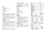
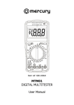
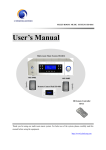
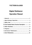
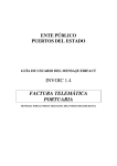
99 Washington Street
Melrose, MA 02176
Phone 781-665-1400
Toll Free 1-800-517-8431
BENCHTOP INSTRUMENT
Visit us at www.TestEquipmentDepot.com
BENCH TYPE DIGITAL
MULTIMETER
DM-1140B
OPERATION MANUAL V2.0
Test Equipment Depot - 800.517.8431 - 99 Washington Street Melrose, MA 02176
TestEquipmentDepot.com
Take off the fuse, and replace an equivalent one then turn on the fuse jack.
Take on the shell, .Screw on the four screws on the button shell by Phillips screwdriver.
1. GENERAL
6. TROUBLE SHOOTING
If the meter does not work properly, take actions as described in this manual to check out if the meter is
defective or not.
Once defective or malfunctioning is confirmed, please contact your local distributor or the manufacturer for
repairing.
The specifications are subject to change without notice.
The content of this manual is regarded as correct. If any error or omits is found, please contact with the
manufacturer.
We hereby will not be responsible for the accident and damage caused by improper operation.
The function stated for this User Manual cannot be the reason of special usage.
This bench type digital multimeter is a steady performance, 4 1/2 digital multimeter. It uses the LCD with
23mm-high figure to make the reading clear and make operation more convenient. A 30mm size LCD with
backlight display makes the reading clear and make operation more convenient.
This instrument has the function of measuring DC and AC voltage, DC and AC current, Resistance, Capacitance,
Hz, hFE, Diodes and Continuity. For AC measuring, it is performed by high accuracy true rms, has the feature of
wide bandwidth measuring and to get accurate rms for AC flow of any waveform or AC+DC.
This instrument adopts double integral A/D converter as its core. It is an ideal tool for labs, factories and
radio-technology.
2. WARNING
The instrument is designed according to IEC1010 standard (safety standard issued by International Electro
technical Committee). Please read the following before operation:
Do not input a value beyond the limited ones when measuring each range.
The voltage less than 36V is the safe voltage. Please check the connection and insulation of test leads to
avoid electric shock when measure the voltage higher than DC36V and AV25V.
The test leads should be far away the test points when change the function and range.
Select correct function and range to avoid fault operation.
Please don’t input voltage value when measuring resistance.
The test leads should be far away the test points and turn off the power when change the fuse.
Introduction for safety symbol:
exists high voltage;
GND
dual insulation
must refer to manual.
3. SPECIFIFACTION
3-1. GENERAL SPECIFICATION
Display: LCD
Max. display: 19999 (4 1/2) digit large LCD with back light and auto polarity display
Measuring method: double integral A/D converter;
Sampling rate: approx. 3 times/sec;
Over range display: “1”;
Working environment: (0~40)℃, R.H<80% ;
Power supply: DC 220V/ 110V, 50/60Hz;
Dimension: 260mm×220mm×82mm.
Weight: approx.2kgs;
Accessories: manual, test leads, power cord, box.
DM-1140B V2.0
3-2. TECHNICAL SPECIFICATION
3-2-1. Accuracy; ±(reading % + the lowest effective digit), temperature for accuracy guarantee (23±5)℃,
R.H<80%, one year guaranteed from the production date.
-8-
Test Equipment Depot - 800.517.8431 - 99 Washington Street Melrose, MA 02176
TestEquipmentDepot.com
-1-
3-2-2. Technical data
DC voltage (DCV)
Range
200mV
2V
20V
200V
1000V
than approx. (30±10) Ω.
Accuracy
±(0.05%reading+3)
±(0.1%reading+5)
Resolution
10uV
100uV
1mV
10mV
100mV
Input impedance: 10MΩ for all ranges;
Overload protection: 200mV range: 250VDC or AC peak value. Other range: 1000V DC or AC peak value.
AC voltage (ACV)
4-10.Frequency measurement
Connect the test leads or shielded cable to COM and VΩHz terminal.
Set the function knob to frequency range, connect test leads or cable across to the signal source or load under
tested.
NOTE:
In noisy environment, it is preferable to use shielded cable for measuring small signal.
Be careful when measuring high voltage circuit.
Do not input voltage over DC 250V or AC peak value voltage aviod to damaging the meter.
4-11.Data hold
Press the hold switch, the data will keep on LCD.
Range
200mV
2V
20V
200V
750V
Input frequency
50Hz–50kHz
Accuracy
50Hz–20kHz
±(0.8%reading+80)
50Hz–5kHz
50Hz–400Hz
±(1.0%reading+50)
Resolution
10uV
100uV
1mV
10mV
100mV
4-12. Backlight displaying
Press
switch, backlight will turn on, press it again, it will turn off.
5. MAINTENANCE
The input value for accuracy guarantee should be larger than 10% of full range.
Input impedance: 2MΩ for all ranges.
Overload protection:200mV range: 250V DC or AC peak value, other range: 1000V DC or AC peak value.
Do not verify the circuit to avoid damaging. Power fuse:200mA/250V; Fuse for measuring current: 2A/250V (this
fuse locate in the current input terminal), 13A/250V fuse locate the main circuit, must be replaced by qualified
personal.
DC current (DCA)
NOTE:
Do not connect the voltage higher than DC1000V or AC 1000V rms.
Do not measure voltage at the Ω range.
When replacing fuse, please take away the test leads from the measuring point and power off at first.
Keep the instrument away from water, dust and shock.
Do not operate the meter in high temperature or strong magnetic place.
Do not use the abrasives or solvents to clean the meter.
Range
20mA
200mA
2A
20A
Accuracy
±(0.35%reading+10)
±(0.8%reading+10)
Resolution
1uA
10uA
100uA
1mA
Max. input voltage drop: 200mV
Max. input current: 20A(within 10s)
Overload protection: 2A/250V fuse,13A/250V fuse
5-1. Fuse replacement
NOTE: Please select fuse of the same specification to replace it.
AC current (ACA)
Range
200mA
2A
20A
Input frequency
50Hz–5kHz
Accuracy
±(0.8%reading+80)
50Hz–400Hz
±(1.0%reading+50)
Max. input voltage drop: 200mV
Max. input current: 20A(within 10s)
Overload protection: 2A/250V fuse,13A/250V fuse
Resistance (Ω)
-2-
Resolution
10uA
100uA
1mA
Power fuse: 200mA/250V; Fuse for measuring current: 2A/250V (this fuse locate in the current input terminal),
13A/250V fuse locate the main circuit.
Power fuse replacement:
Pull out the power cord firstly, takes out the fuse jack on the top of power plug.
Take off the fuse, and replace an equivalent one then turn on the fuse jack.
2A fuse replacement
Press “mA” input jack by finger; take out the fuse jack after turning 90°angle by an inverse hour direction.
Take off the fuse, and replace an equivalent one then turn on the fuse jack.
After press the fuse into the fuse jack, turning 90°angle by an inverse hour direction.
13A fuse replacement (must be replaced by qualified personal.)
Screw off the four screws on the button shell by Phillips screwdriver, take off the upper shell.
Test Equipment Depot - 800.517.8431 - 99 Washington Street Melrose, MA 02176
TestEquipmentDepot.com
-7-
To get more accuracy, it’s better to select the range which the reading is more than 10% of full range.
The max. input current is 2A or 20A (It decided by the COM of red test lead insert into), large current will
blow the fuse. Be careful when measuring 20A range, running large current will make the circuit heat, even
make the circuit damaged.
4-6. Resistance measurement
Connect the black one to “COM” terminal, the red test lead to VΩHz terminal.
Set the knob to Ω range; connect the test leads across to the resistance under measured.
NOTE:
If the resistance is larger than the value of selected range, “1” displays. Set the function knob to a higher
range. When the resistance is larger than 1MΩ, it will take a few seconds to be stable, it’s normal in high
resistance measuring.
When the input terminal is in open circuit, OL displays.
When measuring resistance in-line, be sure that power of the circuit under measured is turned off and all
capacitors are released completely.
If big error occurs, perhaps it effected by other elements in –line or there resist voltage on the ends of this
resistance.
Do not input voltage at the resistance range!
4-7. Capacitance measurement
Set the knob to “F”range. Insert the capacitor under tested to “Cx” terminal according to the polarity,and turn on
the AC+DC measurement switch.
Connect test leads across to the two capacitors. It be careful the polarity.
NOTE:
Set the knob to a higher range when the LCD only displays “1” if the capacitance under tested exceeds the
max. value of selected ranges.
When pressing AC+DC switch before testing, the LCD will not display “0”, which resulted in the higher
input value displaying. If AC+DC switch is at the state of jumping, LCD display the remnant data, which is
normal, won’t affect the test result.
The LCD will not display stable data if it resists creep age badly or destroy the capacitance when measuring
at the higher capacitance range.
Release the capacitor completely to avoid damaging the meter before measuring.
4-8. hFE
Set the function knob to hFE range.
Be sure the transistor is NPN style or PNP style,insert the transmit polarity ,basic polarity, collector to the correct
COM.
4.9. Diode and continuity test
Connect the black one to “COM” terminal and the red test lead to VΩHz terminal(note: the polarity of the red
lead is +).
range, connect the test leads across to the diode (the red one connect anode
Set the function knob to
polarity), the reading is the value of forward voltage drop.
When measuring diode, if making continuity test, buzzer sounds when the resistance between the test leads is less
-6-
Range
200Ω
2kΩ
20kΩ
200kΩ
2MΩ
20MΩ
Accuracy
±(0.1%reading+20)
±(0.1%reading+5)
±(0.5%reading+5)
Resolution
0.01Ω
0.1Ω
1Ω
10Ω
100Ω
1kΩ
Open circuit voltage: less than 3V
Over load protection: 250V DC or AC peak value;
NOTE: At range 200 Ω, short-circuit the test leads to measure the wire resistance and then subtracts it from the
real measurement.
Capacitance (C)
Range
20nF
2uF
200uF
Accuracy
±(3.5%+20)
±(5%+30)
Resolution
1pF
100pF
10nF
Measuring frequency: approx. 400Hz
Measuring voltage: approx. 40mV,
Overload protection: 36V DC or AC peak value
Frequency (FREQ.)
Range
Accuracy
20kHz
200kHz
±(1.0%reading+20)
Resolution
1Hz
10Hz
Input sensitivity: 500mV rms
Overload protection: 250V DC or AC peak value(within 15s)
hFE measuring
Range
Displaying
hFE NPN or PNP
0~1000.0
Test condition
Base current is approx. 10μA,Vce is approx.
3V.
Diode and continuity test
Range
Description
The measuring value is the approx. value
-3-
Test Equipment Depot - 800.517.8431 - 99 Washington Street Melrose, MA 02176
TestEquipmentDepot.com
Test condition
Forward
DCA
is
for forward voltage drop. When the
resistance under tested is less than
30Ω±10Ω, buzzer sounds and display the
approx. value. The open circuit voltage is
approx. 3V.
approx.
1mA,
backward DCV
is
less than 3V.
NOTE: Before connecting the circuit under measured, be sure that the measured value should not exceed the limit
specified in front panel.
4-2 DCV measurement
Connect the black test lead to “COM” terminal and the red one to “VΩHz” terminal.
range, connect the test leads across to the circuit under measured, the polarity will
Set the function knob to
be displayed with the voltage reading value.
Overload protection: 250V DC and AC peak value.
NOTE:
If the voltage under measured is unknown beforehand, start from the highest range and work down.
If only MSD displays “1”, it means over range, should set to a higher range.
Do not input a voltage over 1000V,otherwise, the circuit might be damaged.
Be careful when measuring high voltage circuit.
4. OPERATION
4-1. PANEL DESCRIPTION
4-3 ACV measurement
Connect the black test lead to “COM” terminal and the red one to “VΩHz” terminal.
range, connect the test leads across to the circuit under measured.
Set the function knob to
HOLD
NOTE:
If the voltage under measured is unknown beforehand, start from the highest range and work down.
If only MSD displays “1”,it means over range, should set to a higher range.
To get more accuracy, it’s better to select the range which the reading is more than 10% of full range.
Do not input a voltage over 1000Vrms,otherwise, the circuit might be damaged.
Be careful when measuring high voltage circuit.
AC+DC
4-4. DCA measurement
Connect the black test lead to “COM” terminal and the red one to "mA" terminal(max.2A)or “20A” terminal
(max. 20A).
range, connect the test leads across to the circuit under measured, the polarity will
Set the function knob to
be displayed with the voltage reading value.
WARNING
GROUNDING CONDUCTOR IN POWER CORD
MUST BE CONNECTED TO ENSURE
PROTECTION FROM ELECTRICAL SHOCK.
CAUTION
FOR FIRE PROTECTION REPLACE ONLY WITH:
200mA SLOW FUSE,100/120V
100mA SLOW FUSE,220/240V
NOTE:
If the current under measure is unknown beforehand, start from the highest range and work down.
If only the MSD displays“1”, it means over range, should set to a higher range.
The max. input current is 2A or 20A (It decided by the COM of red test lead insert into), large current will
blow the fuse. Be careful when measuring 20A range, running large current will make the circuit heat, even
make the circuit damaged.
1. LCD
2. Power switch
3. Function knob
5. COM
6. Current (<2A) input terminal and 2A fuse socket
8. Backlight switch 9. Hold switch
10. AC+DC measuring switch
12. Capacitance measuring plug
13. Bracket
14. 110V/220V selector switch
15. Fuse
4. V Ω Hz input terminal
7. 20A current input terminal
11. hFE plug
16. Power plug
The meter is driven by 220V or 110V AC voltage. The voltage is set on 220V when leave factory. If the local line
voltage is 110V, please set the line voltage to 110V by the selector switch on rear panel.
When operating, first connect the power line to power plug, then turn on the power.
-4-
4-5. ACA measurement
Connect the black test lead to “COM” terminal and the red one to "mA" terminal(max. 2A)or “20A” terminal
(max.20A).
range, connect the test leads across to the circuit under measured.
Set the knob to
NOTE:
If the current under measure is unknown beforehand, start from the highest range and work down.
If only the MSD displays“1”, it means over range, should set to a higher range.
Test Equipment Depot - 800.517.8431 - 99 Washington Street Melrose, MA 02176
TestEquipmentDepot.com
-5-