1
MAMI
MANUFACTURING AND MINOR INVENTIONS
Mini-TRACER user manual
X00308
SUPER_TRACER_2ZA5.CDR
O P E R A T I O N
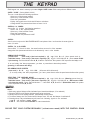
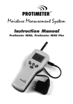
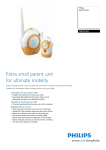
After the installation completed the remote KEYPAD/DISPLAY/S should indicate the following:
Note:Some of the warning (yellow) lights may temporarily be ON to indicate that some of the zones (doors,
windows or motion detectors) are still activated or settling down.
ARM
PER 1
WARN
“MAINS” indication = OFF
‘SYSTEM LOW BATTERY” indication) = OFF
‘LOW BATTERY” in sensors indication) = OFF
“SYSTEM ARMED” indication = OFF
“TRIGGERED” indication = OFF
“DELAY” indication = OFF
“RUNNING” indication = FLASHING
3
2
4
5
“ARMED” indication = OFF
“PERIMETER” indication = OFF
“WARNING” indication = OFF
6
1
5
9
A
A
R
M
2
6
0
B
W
A
R
N
3
7
4
8
*
C
MAINS
BCKUP
WL-TBL
ARMED
TRIGG
DELAY
RUNNG
#
D
Note:
MAINS, BCKUP, WL_TBL, TRIGG and DELAY
indications can individually be made to beep
together with the corresponding display.
(This can only be changed by the installer)
ARMED ZONES 1 TO 6
The RED lights indicate which of the zones are armed.
- A steady light indicates that the zone is permanently armed (24 hrs).
- A running light indicate which zones are being monitored for an alarm condition.
PERIMETER SECTORS 1 TO 6
The GREEN lights indicate which of the PERIMETER sectors are in warning mode.
WARN ZONES 1 TO 6
The YELLOW lights indicate which of the zones are in warning mode.
- The running lights indicate which zones are being monitored for a warning condition.
- A steady light indicates that the zone is currently activated .
This gives you the facility, when leaving your home to check if any windows or doors were left open.
MAINS
MAINS FAILURE indication:
This indicator will be on to indicate that either there is an AC power failure or that the
transformer supplying power to the system has been accidentally unplugged.
BCKUP
SYSTEM BATTERY LOW indication:
The system's battery is left with only 80% of its nominal capacity. (Check mains)
WL-TBL
WIRELESS-DETECTOR BATTERY-LOW/TAMPER indication:
This light will be activated by "poor condition" of the battery in the wireless sensor shown
by the digit display . (Change the battery in the sensor indicated).
ARMED
SYSTEM ARMED indication:
This light is on whenever the system is either armed or set on warning mode.
TRIGG
SYSTEM TRIGGERED indication:
This flashing light warns you that an alarm activation has occurred while you were away.
DELAY
ENTRY/EXIT DELAY indication:
It is often required that some of the zones activate only after a preset time delay. This is done
when you , the user , would like to keep the arm/disarm REMOTE CONTROL in the house
rather then carrying it around at all times. This light will warn that you have initiated a time
delay on one of the zones and that you have a limited time (programmable) to reach the
REMOTE CONTROL or the KEY-PAD and disarm the system.
SYSTEM RUNNING indication:
RUNNG This light reassures you that the system is running correctly. If this indicator does not flash
regularly, please contact your installer.
X00329
-1-
SUPERTRACER_A5_UM.CDR
THE KEYPAD
Each keypad can store in memory up to ten 4-digits USER codes. Each code performs different tasks.
USER 1 CODE : (factory default 1 1 1 1 )
The user 1 code allows the following operations:
- Select any of the 4 preset patterns.
- Select any of the individual zones .
- Reset the system/alarm.
- Display the logged record of the last 255 alarm activations.
- Change his/her own password and those of users 2 to 10.
USER 2,3 & 4 CODES :
User codes 2, 3, 4 allow the following operations:
- Select one of the 4 preset patterns.
- Select any of the individual zones .
- Reset the system/alarm.
- Change his/her own password CODE.
USER 5:
User 5 code is only used in “MULTIUSER MODE” and replaces User 1 and has then the same rights as
users 2, 3 and 4:
USER 6, 7, 8, 9 ,10 CODES:
User codes 6, 7, 8, 9 and 10 allow the same functions as users 2 to 5 but can not
change their own passwords which has to be allocated by user 1 or the installer.
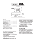
ARMING YOUR SYSTEM :
- preset levels:
(user code) + (the level required) + (A) e.g. 1 1 1 1 # a A . (Arms preset level a).
- Individual zones: (user code) + (the zones required) + (A) e.g. 1 1 1 1 # 1,2,3,5 A . (Arms zones 123&5.
- quick arming: Press and Hold button A, B , C or D to “Quick Arm” the system to the respective level a,b,c or d.
If an exit delay had been programmed, you have a preset time to leave the premises.
(pressing 1 will remove the delay)
DIS-ARMING YOUR SYSTEM
(All zones will be dis-armed).
(user code) + # + #
e.g. 1 1 1 1 # #
(if an entry delay had been programmed, you have preset time to enter the premises and disarm the system).
SELECTING THE WARNING MODE:
(user code) + (the level required) + (B) e.g. 1 1 1 1 # a B . (Warning preset level a).
- preset levels:
- Individual zones: (user code) + (the zones required) + (B) e.g. 1 1 1 1 # 1,2,3,5 B . (Warn-zones 123&5.
- quick warning mode: Press and Hold buttons “ * “ and either A, B , C or D to “Quick Warn mode” the system
to the respective level A, B, C or D.
GENERAL:
Notes :
1- Both entry and exit delays will be indicated by an intermittent bleeper (if so selected).
2- Running" LED'S on the display indicate zones being monitored.
3- Steady" LED'S on the display indicate "permanently" armed zones.
4- To silence "battery low" and "mains failure" bleeper hold "0" until the bleeper is switched off.
5- Pressing these 2 keys simultaneously will cause the following signals to be activated:
* and # will activate a panic signal.
4 and 6 will activate the transmitter for a test transmission.
PLEASE TEST YOUR SYSTEM REGULARLY ( at least once a week) WITH THE CONTROL ROOM
X00329
-2-
SUPERTRACER_A5_UM.CDR
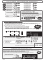
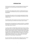
Arming by Users: 1, 2, 3 & 4
OPERATION
USER ? CODE
ARM 1
PER
WARN
1
1
1
1
#
1
A
ARM ZONE 1 BY USER 2
2
2
2
2
#
2
A
ARM ZONE ? BY USER 3
3
3
3
3
#
?
A
?
?
?
?
ARM PRESET PATTERN "A"
?
?
?
?
#
A
A
ARM PRESET PATTERN "B"
?
?
?
?
#
B
A
ARM PRESET PATTERN "C"
?
?
?
?
#
C
A
ARM PRESET PATTERN "D"
?
?
?
?
#
D
A
#
ARM
PER
WARN WARN 1
?
?
?
?
#
1
B
SET TO WARNING PRESET "A"
?
?
?
?
#
A
B
MULTIPLE ENTRIES AND
UPDATING IS ALLOWED
?
?
?
? #
2
?
?
6
#
3
4
5
6
1 3 5 B
Disarming and Resetting by Users: 1, 2, 3 & 4
?
5
1 3 5 A
SET TO WARNING ZONE 1
?
4
?
Set Warning by Users: 1, 2, 3 & 4
DISARM ALL ZONES
3
ZONES
ARM ZONE 1 BY USER 1
MULTIPLE ENTRIES AND
UPDATING IS ALLOWED
2
ALL OFF!
#
If you are User 1 you can change the Codes of users 2, 3 & 4
1 1 1
1
X
#
HOLD
TILL BEEP
THE NEW CODE WILL BE PLAYED BACK ON THE DISPLAY.
- PRESS " # " TO ACCEPT THE NEW CODE
- ANY OTHER KEY WILL ENTER A NEW CODE.
?
?
?
?
#
{
CHANGE CODES OF USER 1 TO 10
NEW CODE (4 DIGITS)
USER NO "1,2,3,4,5,6,7,8,9 or A"
If you are User 1 you can enable or disable Auto-arming
If enabled 15min or 2 hrs after the zone 1 was last triggered the system will arm automatically
ENABLE AUTO - ARM
1
1 1 1
#
A
1
NOTE: THIS OPERATION WILL
SHOW A “ 1 “ ON THE DISPLAY.
HOLD BOTH
TILL BEEP
DISABLE AUTO - ARM
1
1 1 1
#
A
New!!
0
NOTE: THIS OPERATION WILL
SHOW A “ 0 “ ON THE DISPLAY.
HOLD BOTH
TILL BEEP
X00329
-3-
SUPERTRACER_A5_UM.CDR
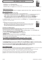
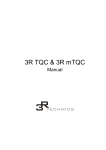
LIST OF USEFUL “QUICK SINGLE AND DOUBLE-KEYS”
HOLD BOTH
TILL BEEP
QUICK WARN LEVEL A
*
A
New!!
QUICK WARN LEVEL B
*
B
New!!
QUICK WARN LEVEL C
*
C
HOLD BOTH
TILL BEEP
New!!
QUICK WARN LEVEL D
*
D
HOLD BOTH
TILL BEEP
PANIC ACTIVATION
*
#
HOLD BOTH
TILL BEEP
HOLD BOTH
TILL BEEP
3
C
QUICK ARMING LEVEL D
D
WIRELESS SUPERVISION REPORT
HOLD
TILL BEEP
HOLD
TILL BEEP
HOLD
TILL BEEP
HOLD
TILL BEEP
*
WIRELESS DETECTOR SUPERVISION REPORT
Please note: This function will work correctly only if both
the “Wireless Zone supervision” option (Pg 10) and the active
wireless zones have been enabled by the installer.
HOLD BOTH
TILL BEEP
An “ F “ for “Faulty”is shown on the display.
New!!
ZONE 6
1
QUICK ARMING LEVEL C
ZONE 5
MEDICAL
B
ZONE 4
6
QUICK ARMING LEVEL B
ZONE 3
4
A
ZONE 2
SEND TEST TRANSMISSION
HOLD BOTH
TILL BEEP
QUICK ARMING LEVEL A
ZONE 1
New!!
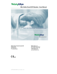
SECTIONAL PERIMETER INTRUSION System (S.P.I.)
An extra 6 perimeter beams can be connected to the new MINI-Tracer. The unit will monitor these
perimeter beams and indicate which beam was triggered. The activation of the beams will only sound locally
and will not report the activation to the control room.
The perimeter beams can be armed by following this procedure:
(Note: For this feature to work correctly you need to do the following:
1- The beams used must be programmed and be functional (aligned)
2-The SPI System option must be enabled by the installer - page 10 .
3- The number of active sectors / beams must be programmed by the installer - page 10
New!!
1 1 1 1
SET SENSITIVITY LEVELS
FOR EACH SECTION
USER1 CODE
1 3
# 9
5
6
#
2
Device
NO
4
BEAM 6
# 0
3
BEAM 5
1 1 1 1
{ {
ARM PERIMETER SECTIONAL BEAMS
2
BEAM 4
5
ARM
PER 1
WARN
BEAM 3
RX
TX
+
- OUT
+ OUT
4
6
BEAM 2
3
2
BEAM 1
1
1
Level
Use the table to select the level (interruption time before alarm)
#
1=0.3 Sec
2=0.5 Sec
3=0.8 Sec
4=1.2 Sec
5= 2 Sec
6= 5 Sec
7=10 Sec
8=20 Sec
WIRELESS ZONE SUPERVISION TEST
(Please note: Both the “Wireless Zone supervision” option (Pg 8) and the active wireless zones (pg 10)
need to be enabled by the installer before this function will work correctly.)
The MINI-TRACER is capable of reporting a faulty wireless detector.
New!!
To display the faulty (non reporting) wireless detector press and hold the * key until it beeps
WIRELESS ZONE SUPERVISION
*
-4ARM
PER
WARN
HOLD
TILL BEEP
An “ F “ is shown on the display.
X00329
-4-
Faulty detector shown on the ARM Leds
SUPERTRACER_A5_UM.CDR
THE REMOTE CONTROL
A
The remote controls are supplied with either 1 , 2 (standard) or 3 buttons:
B
C
- BUTTON A is used for Emergency/Panic.
- BUTTON B is used to arm, disarm, and reset the system.
- BUTTON A & B pressed together will send a test signal to the control room (only with radio or tele-communicator)
REMOTE PANIC BUTTON “A”:
- button “A” will ALWAYS trigger the emergency operation and send a “Panic “ signal to the control room.
ARM / DISARM BUTTON “B”
To arm the system : (see table on back page)
Press BUTTON B. You now have four options: ( not with SNIPER models)
1- Let the system automatically step through the three levels "A", "B" , "C" and automatically arm level "D".
2- While stepping through the preset levels press BUTTON A to select that level in ARM MODE
3- While stepping through the preset levels press BUTTON B to select that level in WARNING MODE
4-While stepping through the levels press both buttons at the same time to access the CUSTOMER
programming mode (see below) which allows you to change the zone configuration in that pattern.
To disarm the system, ( From armed /warning status) press BUTTON B until a two beeps are heard through the
buzzer /siren or the remote display.
NOTE:
- A single beep will indicate that the system has been armed.
When arming, 6 short beeps indicate that one or more of the zones are in the open condition.
After the warning the system will Arm regardless but will not activate if the zone stays open.
-Two beeps will indicate that the system has been disarmed.
A
B
C
ENTERING THE WARNING MODE
Note that following mode WILL NOT trigger the siren or send a signal to the Control Room.
The buzzer will warn you whenever a zone is being violated.
Select the designated level to be in the warning mode. (Refer to the above table )1. Press BUTTON B once.
The system automatically steps through levels "A" to " D."
2. Stop the display at the level required by pressing BUTTON B once .
3. The system is now SET TO WARNING MODE at this selected level.
GENERAL NOTES:
-Resetting of the system may be done at any time using BUTTON B.
-Indications on the remote display units are retained until the system is armed again. This will allow you to ascertain
the cause of the alarm even after resetting
CUSTOMER PROGRAMMING MODE (using the remote control)
Note: It is strongly recommended that this be done in consultation with your installer.
If you have entered the programming mode (4 on Page 1) a yellow light will be ON for zone No. 1.
The two remote buttons have now assumed different roles where BUTTON B will toggle the corresponding red light
and BUTTON A will step to the next zone. In this way it is possible to change the patterns to suit new requirements.
An error may be easily rectified using BUTTON A to toggle back or BUTTON B, to step right around.
To leave the programming mode PRESS BOTH BUTTONS TOGETHER (BUTTON A & BUTTON B).
Should you loose your remote, call your installer to replace the remote and change your code.
AUTO - ARMING (if enabled)
When the auto-arming feature is enabled (programmable for 2 hours or 15 minutes by installer) the system will arm itself if
no movement or any other activations have been detected within the selected time period.
This function is useful when you forget to arm your alarm system. The system will arm itself 15 min /2 hours after
you have left the house or went to bed. You can turn the auto-arming on and off as you please.
Note: Entry / Exit will only function correctly if Zone 1 is the last zone triggered when you leave your
premises. Level ‘A’ will be the “at home /sleep” arming pattern and Level ‘D’ the “away” arming pattern.
X00329
-5-
SUPERTRACER_A5_UM.CDR
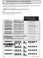
MULTI-USER Operation (ZONE-SHARING):
One important feature of MULTI-TRACER is its ability to operate in MULTI-USER or ZONE-SHARING mode.
(This option is set in the option register 1.- Page 8)
This mode allows up to 4 users to independently operate the same control panel and accessories. In this mode USER 1 (who normally
has special rights ) is replaced by a user 5 who has the same rights as users 2,3 and 4. USER 6, 7, 8, 9 & 10 are not available in this mode.
Understanding how the zone-sharing concept works is simple .... just remember the following:
Assume that users 2 and 3 are sharing some zones....
-To DISARM shared zones think of the OR function (e.g. EITHER user 2 OR user 3 can disarm )
-To ARM shared zones think of the AND function ( e.g. BOTH user 2 AND user 3 must arm)
It is possible to provide each user with a specially coded remote control. (Ask your installer about it.)
EXAMPLE:
USER 2 HAS ACCESS TO ZONES 2, 3 and 4 in common with user 3
USER 3 HAS ACCESS TO ZONES 6, 7 and 4 in common with user 2
ZONE 4 can be activated only if user 2 AND 3 have armed it.
but can be deactivated either by user 2 OR 3.
ARM
ARM
PER 1
WARN
WARN
OPERATION
USER CODE
PATTERN
2
2
2
2
#
A
DISARM PRESET PATTERN "B"
2
2
2
2
#
#
ARM PRESET PATTERN "C"
X3
X3
X3
X3
#
A
DISARM PRESET PATTERN "C"
X3
X3
X3
X3
#
#
ARM PRESET PATTERN "D"
X4
X4
X4
X4
#
A
DISARM PRESET PATTERN "D"
X4
X4
X4
X4
#
#
ARM PRESET PATTERN "A"
X5
X5
X5
X5
#
A
DISARM PRESET PATTERN "A"
X5
X5
X5
X5
#
#
ARM PRESET PATTERN "B"
1
4
5
6
2 3 4
5
6
2
3
Every time one of the users arms/disarms the system , the new condition is reported to the control room.
MULTIPLE ENTRIES ARE ALLOWED
(ONLY WITHIN ALLOWED MASK IN MULTIUSER)
SET TO WARNING (YELLOW LEDS)
CHANGE CODE OF USER 2
2
2
2
2
2
2
2
2
2
#
1 3 5 A
#
2
2
2
EXISTING USER 2 CODE
THE NEW CODE WILL BE PLAYED BACK ON THE DISPLAY.
- PRESS " # " TO ACCEPT THE NEW CODE
- ANY OTHER KEY WILL ENTER E NEW CODE.
CHANGE CODE OF USER 3
3
3
3
3
EXISTING USER 2 CODE
CHANGE CODE OF USER 4
4
4
4
4
EXISTING USER 2 CODE
CHANGE CODE OF USER 5
5
5
5
5
EXISTING USER 2 CODE
X00329
-6-
B
?
?
?
#
#
?
HOLD
TILL BEEP
NEW CODE (4 DIGITS)
#
?
?
?
?
#
?
?
?
?
#
?
?
?
?
#
HOLD
TILL BEEP
#
HOLD
TILL BEEP
#
HOLD
TILL BEEP
mini TRACER_A5_UM.CDR
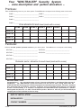
Your "MINI-TRACER" Security System
- zone description and pattern allocation –
Premises:
There are SIX working zones on your alarm system. These SIX zones correspond to the following areas in the house.
ZONE 1. _________________________________ZONE 5. _________________________________
ZONE 2. _________________________________ZONE 6. _________________________________
ZONE 3. _________________________________
ZONE 4. _________________________________
Zone allocation for each level (mark with a cross)
ZONE 1 ZONE 2 ZONE 3 ZONE 4 ZONE 5 ZONE 6
Level “A
Level “B”
Level “C”
Level “D”
Perimeter:
. are also SIX optional perimeter sectors on your alarm system. These SIX sectors correspond to the following
There
SECTOR 1__________________________________ SECTOR 5 _________________________________
SECTOR 2 _________________________________ SECTOR 6. _________________________________
SECTOR 3 _________________________________
SECTOR 4 _________________________________
Perimeter sector allocation for each level (mark with a cross)
SECTOR 1
SECTOR 2
SECTOR 3
SECTOR 4
SECTOR 5
SECTOR 6
Level “A
Level “B”
Level “C”
Level “D”
MANUFACTURER'S NOTE
Congratulations !! You are now the owner of one of the most sophisticated and featured alarm systems in
South Africa. The “ MINI-TRACER” system has evolved over the last 15 years, during which time the
STATE OF THE ART technology was continuously applied and manufacturing perfected. This latest model has
been developed with the End-user, insurance companies and corresponding armed response pre-requisites
in mind - it is user friendly, it is versatile, it encompasses all latest features and requirements of a modern
alarm system and above all, it is 100% a South African product. We trust it will serve you well and afford you
complete peace of mind, whether at home or away
DATE OF INSTALLATION: ____________________________________
INSTALLED BY: ____________________________________________
CONTACT NUMBER: ________________________________________
X00329
SUPERTRACER_A5_UM.CDR