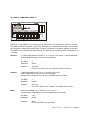
1
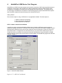
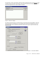
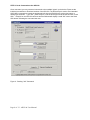
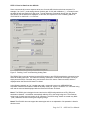
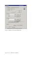
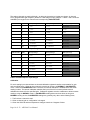
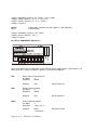
ADU100 USB Data Acquisition Interface
User Manual
Ver 1.2
www.ontrak.net
Ontrak Control Systems reserves the right to change product specifications to improve
the product.
Although every attempt has been made to ensure the accuracy of the material contained in
this manual, Ontrak Control Systems assumes no liability for inadvertent errors.
Warranty : This ADU100 is warranted from defects in workmanship and materials for a
period of 90 days. Liability for defects is limited to the purchase price of the product. This
warranty does not apply to defects resulting from improper modifications or use outside
published specifications.
Copyright 2003 ONTRAK CONTROL SYSTEM S INC.
Page 2 of 23 ADU100 User Manual
Table Of Contents
1.
W hat is Included and W here to Start
4
2.
ADU100 USB Data Acquisition Interface Features
4
3.
Connecting the ADU100 to a USB Bus
5
4.
AduHidTest USB Device Test Program
6
5.
ADU100 Command Summary
11
6.
ADU100 Command Descriptions
11
6a) Analog Commands
6b) Relay Commands
6c) Digital I/O Commands
6d) Event Counter Commands
6e)Special Feature Commands
11
16
17
19
20
7.
The ADU100 Software Development Kit ( SDK )
21
8.
Electrical Specifications
22
Page 3 of 23 ADU100 User Manual
1.
What is Included and Where to Start
The ADU100 ships complete with a 10' USB cable, this User Manual and a 3.5" diskette titled ADU-SDK.
The ADU-SDK diskette inlcudes the following files;
AduHid.dll
AduHidTest.exe
AduHidHelp.chm
VisualC-EG
VisualBasic-EG
BorlandC-EG
Various support files
DLL to allow applications to communicate with the ADU100 on the USB bus.
Software application used to test ADU products and allow programmers to
become familiar with the ADU ASCII commands.
Software development kit ( SDK ) in CHM ( Windows Help File ) format.
( folder)
Visual C program examples from SDK
( folder)
Visual Basic program examples from SDK
( folder)
Borland C program examples from SDK
First time users should first review the ASCII command set for the ADU100 and then use AduHidTest to
become familiar with the operation of the various features of the product.
Note: The AduHid DLL requires one of the following Windows operating systems. 98SE, 2000 or XP
Application programs should be written using the Software Design Kit ( SDK ) located on the ADU-SDK
diskette. The SDK contains explanations of how the various communication pipes can be accessed using
the AduHid DLL. Example code is given for Visual Basic, Visual C and Borland C. The SDK help file is
designed to be run on the development PC when programming. This allows programmers to cut-andpaste specific functions directly into an application. Additional examples and applications are posted on
our web site at www.ontrak.net
2.
ADU100 USB Data Acquisition Interface
-3, ISOLATED ( 3000V ) 16-Bit Analog Inputs.
-Programmable PGA gives full scale input ranges from 0-19mV to +/-10V
-Low noise Sigma Delta A/D
-Internal self-calibration function for true 16-bit resolution
-2.5000V and 5.00V reference outputs to allow direct connection of strain gauges.
-High quality Aromat PA-series relay offers superior performance.
-4 Digital I/O Lines
-1, N. O. relay contact output rated 5.0A @ 120VAC, 5.0A @ 30VDC
-Programmable watchdog functions.
-Bi-colour LED status indicator.
-Self-resetting, fused 5V output
-Auxiliary RS232 port for connecting legacy RS232 devices. ( ADR series )
-High quality cage-clamp type terminal blocks.
-Uses standard HID drivers included with Windows 98SE,2000,XP
-Mini-driver ( DLL ) provided for use with VB,VC, LabVIEW and TestPoint
-Programming examples and sample code included for VB, Visual C++
-Four, 16-bit event counters ( one high speed capable )
-Programmable de-bounce setting for event counters.
-Bus Powered, No external power supply required.
-Meets IEC61000-4-2 ESD protection for USB port.
-Available in enclosure or as PCB only.
Page 4 of 23 ADU100 User Manual
3.
Connecting the ADU100 to a USB Bus
The ADU100 can be connected to the USB bus via the enclosed 10' A-B USB cable. The cable provides
both power and communications connections to the ADU100. When first connected, the STATUS led will
turn RED indicating power is applied. A message will flash on the screen indicating;
“New hardware Found”
ADU100 USB Data Acquisition Interface
Depending on the version of Windows , the host may prompt to search for a driver. Select,
Let Windows Search for a Driver
and click next.
After a few seconds, the STATUS led will turn green indicating enumeration is complete. The
enumeration process is completely transparent to the application program as it is completed by the
Windows operating System
The STATUS led will remain green unless a watchdog timeout ( See Special Commands Section )
occurs.
The ADU100 can be connected directly to the host hub or either, external powered, or non-powered
hubs.
Caution: ( Use of System Standby ): If the Windows operating systems puts the system into “
Suspend ” mode, all USB hubs are issued a Reset when the Suspend mode is exited. This will cause the
ADU100 to lose power briefly, resulting in the event counter data being lost and reversion to the power up
state. Open the power options section in the Windows control panel and ensure “System Standby” is set
to never.
Caution: ( Use of PWR Terminals ): The auxiliary power connections labelled VDD and GND are a nonisolated output and no external power supply should be connected to these terminals. The power output
is provided to allow use of dry contact inputs to the digital input lines. If the supply is to be used with dry
contact inputs, GND should be connected to COM, and the dry contact connections made between VDD
and the selected digital input line. If this power output is used for external circuits, up to 100 mA can be
drawn depending on how much current is drawn from the 5.000V reference output. The total current
drawn from the 5.000V reference and VDD should not exceed 100mA.
Page 5 of 23 ADU100 User Manual
4.
AduHidTest USB Device Test Program
AduHidTest is a USB Device test program used to test the connection of ADU data acquisition devices to
a USB port. The program is also a useful tool to allow programmers to become familiar with the ADU
command set. The program is located in the root directory of the ADU-SDK disk. The program can be
run from floppy or transferred to the hard drive. Note that the program requires the AduHid.dll to operate
and it should be copied to the same directory as the AduHidTest.exe file.
Getting Started:
There are three steps in using a USB device in any application software. The three steps are ,
1. Obtain a handle for the ADU100.
2. Send commands to the ADU100.
3. Receive data from an ADU100.
STEP 1: Obtain a handle for the ADU100
A handle is a unique code that application software uses to identify a USB device for the purpose of
reading and writing to the device. A USB bus can have up to 128 devices connected to a single host and
there are three criteria that can be used to open a handle. The three criteria are, Vendor ID, Product ID
and Serial Number. If a single device is connected to the bus, any of the three criteria may be used. If
multiple devices are connected, we recommend using the Serial Number to open the handle ( All ADU
devices have their unique serial number printed on the top label ) The AduHidTest program main Window
is shown in Figure 1.
Figure 1: AduHidTest Main Window
Page 6 of 23 ADU100 User Manual
The Open/Close section of the window is where the handle is determined. Click on the Show List button
to view the devices connected to the USB bus. ( Note: Only ADU devices will be listed ) Figure 2 is the
window that appears when the Show List Button is clicked.
Figure 2: " Show List " Display
The display indicates that there is an ADU100 device connected with serial number B00001. Select the
device by clicking on the displayed text. The AduHidTest main window will now display the product ID
and Serial number. Click the By Serial # radio button and then click Open to open the handle to the
selected ADU100.
Figure 3: Connected to B00001
Page 7 of 23 ADU100 User Manual
STEP 2: Send Commands to the ADU100
Once connected, you may now send commands to the available "pipes" on the device. Pipes are the
individual connections to functional sections of the ADU100. The Device Pipe is used to send standard
ASCII ADU commands to control the peripherals built into the ADU100 such as the relay output or
analog input channels. Type "sk0" ( Close relay K0 ) into the device pipe send window and click Send
ADU . Relay K0 on the ADU100 will close and the software will display a small "OK" next to the Send
ADU button indicating the command was sent.
Figure 4: Sending "sk3" Command
Page 8 of 23 ADU100 User Manual
STEP 3: Receive Data from the ADU100
Some commands will cause a response to be sent from the ADU device to the host computer. For
example, if an "ruc07" ( read analog channel 0 with a gain of 128 ( with calibration ) ) command is sent,
the ADU100 will send back the 5 digit count. To read responsive commands, simply click the Receive
ADU button and the data will be displayed. In this case, the response is 37357 indicating AN0 is at;
37357/65535 X .01953125 = 11.1334 mV.
Figure 5: Sending "ruc07" and Receiving Analog Data
The RS232 Pipe is used to send and receive ASCII strings to any RS232 based device connected to the
ADU100 auxiliary serial port. The method of sending commands is identical to device pipe, in that you
simply enter the ASCII command string, and click the Send 232 button. Data is received, and then
displayed when the Receive 232 button is clicked.
In the following example, an "rd" ( analog array read ) command is sent to an ADR2000B Data
Acquisition Interface connected the ADU100 auxiliary serial port. Figure 6 shows the "rd" command being
sent and the returned data displayed after the Receive 232 button is clicked.
Note1: The RS232 pipe is designed to send and receive ASCII strings which use a CR ( 0Dh) as a
termination character. AduHidTest automatically adds the CR to the string being sent. The maximum
string length for both send and receive is 40 characters. The ASCII string should not contain any NULL
( 00h ) characters in both incoming and outgoing strings.
Note2: The ADU100 does not support the stream pipe and so no explanation of its operation is listed in
this document.
Page 9 of 23 ADU100 User Manual
Figure 6: Sending "rd" Command to RS232 Pipe
Page 10 of 23 ADU100 User Manual
5. ADU100 Command Summary
ANALOG INPUT COMMANDS
RUNng
RBNng
Returns unipolar analog value of analog channel n using gain of g (n= 0,1 or 2, g =0 -7)
Returns bipolar analog value of analog channel n using gain of g (n= 0,1 or 2, g =0 -7)
RUCng
Returns unipolar analog value of analog channel n using gain of g (n= 0,1 or 2, g =0 -7)
( With self-calibration )
Returns bipolar analog value of analog channel n using gain of g (n= 0,1 or 2, g = 0 - 7)
( With self-calibration )
RBCng
RELAY COMMANDS ( PORT K )
SK0
RK0
RPK0
Sets relay K0 ( closes contact )
Resets relay K0 ( opens contact )
Returns status of relay K0
DIGITAL COMMANDS ( PORT A )
CPAxxxx
SPAxxxx
MAdd
RAn
SAn
RPAn
RPA
PA
P1
P0
PU
Configures data direction of PORT A. ( x = 1 for input, 0 for output )
Outputs binary data to PORT A ( x =0 or 1 )
Outputs decimal data to PORT A ( ddd= 00 to 15 )
Resets I/O line, specified by n in PORT A ( n = 0,1,2 or 3 )
Sets I/O line, specified by n in PORT A ( n = 0,1,2 or 3 )
Returns status of Input specified by n ( n= 0 , 1, 2 or 3 )
Returns status of PORT A in binary format.
Returns status of PORT A in decimal format.
Turns on light pull-ups on PORT A
Turns off light pull-ups on PORT A
Returns present pull-up status ( 0 for OFF, 1 for ON )
EVENT COUNTER COMMAND SUMMARY
REx
RCx
DBn
DB
Returns present count of event counter ( x = 0,1,2 3 or H )
Returns present count and clears event counter ( x = 0,1,2, 3 or H )
Sets de-bounce time of event counters ( n=0,1,2 or 3 )
( 0 =100ms, 1 = 10ms, 2 = 1ms, 3 = 100us )
Returns present de-bounce setting.
SPECIAL FEATURE COMMAND SUMMARY
SBn
SB
WDn
WD
Sets baud rate of axillary RS232 port. (n = 0,1,2 or 3 )
( 0 =9600, 1 = 19.2K, 2 =38K, 3 = 56K )
Returns present baud rate setting.
Sets watchdog timeout length (n = 0,1,2 or 3 )
( 0 =WD OFF , 1 = 1s, 2 =10s, 3 = 1min. )
Returns watchdog setting.
Page 11 of 23 ADU100 User Manual
6. ADU100 Command Descriptions
All commands are specified as non-terminated ASCII strings. The maximum length of command and
data strings is 7 bytes. Commands are passed via the AduHid DLL to the ADU100 as a seven byte
packet and unused bytes are sent as NULL ( 00h ).
6a) ANALOG INPUT COMMANDS
The ADU100 features three, 16 bit analog inputs AN0, AN1 and AN2. Also featured in the analog section
are two reference outputs suitable for use with external sensors such as strain gauges or potentiometers.
The 2.5V REF output can source up to 10mA and the +5 VDC output can source up to 100mA. All
analog inputs and reference outputs feature 3000V optical isolation from the USB bus and other I/O
functions.
Figure 7: Analog Connections
Input Connections:
Two of the inputs ( AN0 and AN1 ) are low level inputs that can be operated as two single ended inputs
or used as one differential input. To operate AN0 and AN1 as two separate single-ended, unipolar inputs,
LCOM MUST be shorted to AGND. Input signals are then applied to AN0 and/or AN1 with AGND used
as the analog ground input. Figure 8 shows single ended voltages ( VA and VB ) connected to the
analog inputs. To operate the inputs as a differential pair, + in is connected to AN1, -in is connected to
LCOM and AGND is used as the analog ground input. The differential measurement is then made by
simply reading the AN1 input. NOTE: in differential mode, LCOM is NOT shorted to AGND and there is
no connection to AN0. An example of a differential input is shown using a strain gauge in Figure 9.
The third input ( AN2) is a high level input and operates as a single ended input only. Input voltages are
simply applied between AN2 and AGND.
Page 12 of 23 ADU100 User Manual
6a) NOTE 1: Bipolar Input Connections to AN0 and AN1:
Special considerations must be made when connecting bipolar input voltages to AN0 and/or AN1. When
operating in bi-polar mode the inputs are actually pseudo-bipolar as LCOM is used as the reference for
the bipolar input voltages. LCOM must not be connected to AGND and NO CONNECTION should be
made to 2.5V REF, AGND, AN2 or +5VDC. Bipolar input ranges can be used with AN2 without any
special considerations.
Figure 9a : Bipolar Input Connections to AN0 and AN1
Page 13 of 23 ADU100 User Manual
The analog channels are read individually, as either single-ended or bi-polar type inputs. An internal
PGA ( programmable gain amplifier ) allows for a wide range of input voltages. Tables 1 and 2 show the
available input ranges for the channels and corresponding GAIN SETTING.
G AIN S E T T IN G
G AIN
AN 0 Input R ange
AN 1 Input R ange
AN 2 Input R ange
0
1
0 - 2.5V
0 - 2.5V
D o N o t U se
1
2
0 - 1.25V
0 - 1.25V
0 - 10V
2
4
0 -.625V
0 -.625V
0 - 5V
3
8
0 - 0.3125V
0 - 0.3125V
D o N o t U se
4
16
0 - 0.15625V
0 - 0.15625V
D o N o t U se
5
32
0 - 78.125mV
0 - 78.125mV
D o N o t U se
6
64
0 - 39.0625mV
0 - 39.0625mV
D o N o t U se
7
128
0 - 19.53125mV
0 - 19.53125mV
D o N o t U se
Table 1: Available Unipolar Input Ranges
G AIN S E T T IN G
G AIN
AN 0 Input R ange
AN 1 Input R ange
AN 2 Input R ange
0
1
+/- 2.5V
+/- 2.5V
D o N o t U se
1
2
+/- 1.25V
+/- 1.25V
+/- 10V
2
4
+/-.625V
+/-.625V
+/- 5V
3
8
+/- 0.3125V
+/- 0.3125V
D o N o t U se
4
16
+/- 0.15625V
+/- 0.15625V
D o N o t U se
5
32
+/- 78.125mV
+/- 78.125mV
D o N o t U se
6
64
+/- 39.0625mV
+/- 39.0625mV
D o N o t U se
7
128
+/- 19.53125mV
+/- 19.53125mV
D o N o t U se
Table2: Available Bipolar Input Ranges
Calibration
For each analog input channel there are internal calibration registers that allow compensation for gain
and zero offset errors. When an input channel is read it can be done in NORMAL or CALIBRATED
mode. When the CALIBRATED mode is selected, an internal calibration is initiated before the actual
reading is taken. The internal calibration switches the input of the A/D to internal references and
calibrates the channel for the specified gain. Calibration registers store the coefficients to allow accurate
readings using the NORMAL mode. A CALIBRATED reading takes over three times as long as a
NORMAL reading as thus, CALIBRATED readings are generally only taken at the following times;
1. The first time a channel is read.
2. When a channel gain or configuration is changed.
3. When the ADU100 ambient temperature changes more than 2 degrees Celsius.
Page 14 of 23 ADU100 User Manual
Command Structure:
The command used to read the analog channels is composed of three ASCII characters and two ASCII
numbers for a total for five bytes. The first character is an “R” and is constant. The second character is
either a “ U “ or “ B ” to indicate whether the measurement is to be a either a unipolar or bipolar type.
The third character is either an “ N ” or “ C “ to indicate if the measurement is a normal type or one to be
done with a calibration . The first number specifies the input channel to be read and is either 0, 1 or 2.
The last number is the gain setting and ranges from 0 to 7.
Analog Command Composition
1st Character
2nd Character
3rd Character
4th Character
5th Character
R
( Constant)
U for unipolar or B for bi-polar
N for normal or C for calibrated
Channel ID#, 0 = AN0, 1 = AN1, 2 = AN2
Gain Setting of 0 to 7
The response to all analog read commands is a 5 digit decimal number from 00000 to 65535.
To convert the READING to an actual voltage, use the following formulas ;
AN0 and AN1 in Single-Ended mode;
Voltage = READING / 65535 X ( 2.5V / GAIN )
AN0 and AN1 in Bi-Polar mode;
Voltage = READING / 65535 X ( 5V / GAIN ) - ( 2.5V / GAIN )
AN2 in Single-Ended mode;
Voltage = READING / 65535 X ( 10V / GAIN )
AN2 in Bi-Polar mode;
Voltage = READING / 65535 X ( 20V / GAIN ) - ( 10V /GAIN)
A few examples;
RUN07
34567
( Read AN0 in unipolar mode with a gain of 128, without calibration )
( returned data )
Voltage = READING / 65535 X ( 2.5V / GAIN )
Voltage = 34567 / 65535 X ( 2.5V / 128 )
Voltage = 10.3019mV
RBN14
54690
( Read AN1 in bi-polar mode with a gain of 16, without calibration )
( returned data )
Page 15 of 23 ADU100 User Manual
Voltage = READING / 65535 X ( 5V / GAIN ) - ( 2.5V / GAIN )
Voltage = 54690 / 65535 X ( 5V / 16 ) - ( 2.5V / 16 )
Voltage = 54690 / 65535 X ( 5V / 16 ) - ( .15625 )
Voltage = 0.10453 V
RUC21
42133
( Read AN2 in unipolar mode with a gain of 1, with calibration )
( returned data )
Voltage = READING / 65535 X ( 10V / GAIN )
Voltage = 42133 / 65535 X ( 10V / 1 )
Voltage = 6.4290 V
6b) RELAY COMMANDS ( RELAY K0 )
There is one type A relay contact output on the ADU100 rated at 5A@120VAC or 5A at 30VDC. The
relay can be SET ( closed ) or RESET ( opened ). The relay commands are;
SK0
Sets ( closes ) relay contact K0
# of Bytes
3
Response
NONE
Example;
RK0
;closes contact K0
Resets ( opens )relay K0
# of Bytes
3
Response
NONE
Example;
RPK0
SK0
RK0
;opens contact K0
Returns status of relay K0
# of Bytes
4
Response
1 byte ( 0 or 1 )
Example;
RPK0
1 ( response)
Page 16 of 23 ADU100 User Manual
;Relay K0 is closed.
6c) DIGITAL COMMANDS ( PORT A )
PORTA is a 4 byte digital I/O port. The port can be configured in any configuration of inputs or outputs.
The power up default is all inputs. Light pull-up resistors can be enabled under software control to allow
the connection of external dry contact inputs. There are a multitude of commands available to read and
write PORT A in both binary and decimal format. The port lines can be read or written individually, or as
a 4 bit port.
CPAxxxx
SPAxxxx
MAdd
Configure data direction of PORT A ( x= 1 for input, 0 for output ) ( order is MSB-LSB )
Order is MSB-LSB and all four bits must be specified.
# of Bytes
Response
7
NONE
Example;
CPA1000
.
( PA3 is set to input, PA0, PA1 and PA2 are set as outputs )
Writes binary data to PORT A ( x= 1 for HIGH, 0 for LOW)
Order is MSB-LSB and all four bits must be specified.
Individual lines configured as inputs are not affected by this command.
# of Bytes
Response
7
NONE
Example;
SPA1110
.
( PA3, PA2, and PA1 are set HIGH, and PA0 is reset to LOW )
Writes decimal data ( dd ) to PORT A ( dd = 0 to 15 )
Individual lines configured as input are not affected by this command.
# of Bytes
Response
3 or 4
NONE
Example;
MA15
( All lines of PORT A are set HIGH )
Page 17 of 23 ADU100 User Manual
RAn
Resets I/O line specified by n ( n= 0 , 1, 2 or 3 )
# of Bytes
3
Response
NONE
Example;
SAn
Sets I/O line specified by n ( n= 0 , 1, 2 or 3 )
# of Bytes
3
Response
NONE
Example;
RPAn
RPA2
1 ( response)
;PA2 is High.
Returns status of PORT A in binary format.
# of Bytes
3
Response
4 bytes ( 0000 tp 1111 binary )
Example;
PA
SA1
( PA1is set to HIGH )
Returns status of I/O line specified by n ( n= 0 , 1, 2 or 3 )
# of Bytes
4
Response
1 byte ( 0 or 1 )
Example;
RPA
RA2
( PA2 is reset to LOW )
RPA
0100 ( response)
;PA2 is High, PA0,PA1 and PA3 are Low
Returns status of PORT A in decimal format.
# of Bytes
2
Response
2 bytes ( 00 to 15 in decimal )
Example;
PA
15 ( response)
;All lines are High..
P1
Enables light pull-ups on I/O all lines configured as inputs.
# of Bytes
2
Response
NONE
P0
Disables light pull-ups on I/O all lines configured as inputs. ( DEFAULT SETTING )
# of Bytes
2
Response
NONE
PU
Returns status of light pull-ups.
# of Bytes
2
Response
1 Byte ( 0 if disabled, 1 if enabled )
Page 18 of 23 ADU100 User Manual
An example of dry contact connections using the internal pull-ups is shown in figure 12.
Figure 12: Dry contact Connections
Note that when using the internal pull-ups, the inputs read a logic 1 or HIGH when the contact input is
OPEN or there is nothing connected to the input. Dry contact inputs are then connected between GND
and the associated input and return a logic 0 or LOW when the contact is closed.
6d) EVENT COUNTER COMMANDS
Each digital input line on PORTA has an event counter associated with it. The event counters count low
to high transitions and store them in a 16 bit counter that can be read or, read and cleared. The event
counters are numbered 0 to 3 and count from 00000 to 65535 followed by a rollover to 00000. The debounce time of the event counters can be set from 100us to 10ms. Additionally, PA0 has a high speed
event counter ( H ) that is not affected by the de-bounce setting. Event counter H has a maximum input
frequency of 250KHz.
REx
Returns present count of event counter ( x = 0,1,2 3 or H )
# of Bytes
3
Response
5 bytes ( 00000 to 65535 in decimal )
Example;
RCx
RE1
00023 ( response)
;PA1 has seen 23 Low to High Transitions
Returns present count and clears event counter ( x = 0,1,2, 3 or H )
# of Bytes
3
Response
5 bytes ( 00000 to 65535 in decimal )
Example;
RC3
00156 ( response)
;PA3 has seen 156 Low to High Transitions
; ( Event Counter 3 is cleared )
Page 19 of 23 ADU100 User Manual
DBn
Sets de-bounce time of event counters ( n=0,1 or 2 )
( 0 =100us, 1 = 1ms ( Default ) , 2 = 10ms )
# of Bytes
3
Response
NONE
Example;
DB
DB0
;De-bounce is set to 100us
Returns present de-bounce setting.
# of Bytes
2
Response
1 bytes ( 0,1, or 2 )
Example;
DB
0 ( response)
;De-bounce is set to 100us
6e) SPECIAL FEATURE COMMANDS
The ADU100 has several special features including a host watchdog timer and an auxiliary serial
( RS232 ) port. The following commands are used to implement these features.
The RS232 port has a programmable baud rate from 9600 to 56K. This setting determines the BAUD
rate used for both transmit and receive. This parameter should be set before RS232 transmission or
reception commences.
SBn
Sets baud rate of auxiliary RS232 port. (n = 0,1, 2 or 3 )
( 0 =9600 ( Default ) , 1 = 19.2K, 2 =38K, 3 = 56K )
# of Bytes
3
Response
NONE
Example;
SB
SB3
;Sets Baud rate to 56K
Returns present baud rate setting.
# of Bytes
2
Response
1 bytes ( 0,1, 2 or 3 )
Example;
SB
0 ( response)
;Baud Rate is 9600
A programmable host watchdog is provided to allow predicted operation in the event the host PC stops
communicating with the ADU200. Upon timeout, the relay K0 is RESET, WD =0, and the status
indicator will turn from GREEN to RED. Any command sent to either the DEVICE or RS232 pipe will
reset the watchdog timer. To determine if a watchdog timeout has occurred, read the timer setting. If the
watchdog was set to 2, and no command was sent for 10 seconds, a 0 will be returned indicating a
timeout has occurred. Following a timeout, the host must reload the timer setting as a timeout causes the
setting to be set to 0 ( WD OFF )
WDn
Sets watchdog timeout length (n = 0, 1, 2 or 3 )
( 0 =WD OFF ( DEFAULT ) , 1 = 1s, 2 =10s, 3 = 1min. )
# of Bytes
3
Response
NONE
Example;
WD2
;Sets WD timeout to 10s
Page 20 of 23 ADU100 User Manual
WD
Returns watchdog setting.
# of Bytes
2
Response
1 bytes ( 0,1,2 or 3 )
Example;
WD
0 ( response)
;Watchdog not enabled or timeout has occurred.
7. The ADU100 Software Development Kit (SDK)
Application programs must use the AduHid DLL provided to send commands and receive data from the
ADU100. This is done using simple API calls from the application language
AduHid DLL location
The SDK is located on the ADU-SDK diskette and includes explanations of how the pipes to the various
ADU100 features operate.
The SDK contains examples for use with Visual Basic, Visual C and Borland C. Additional programming
tutorials and applications are located at www.ontrak.net
Page 21 of 23 ADU100 User Manual
Electrical Specifications
S upply V o ltage
N O N E ( B us P o wered )
S upply C urrent
180mA T ypical, 200mA M aximun
O perating T emperature
0 - 50 C
Low -Lev el Analog Inputs ( 2 )
R eso lutio n
16 B its
T ype
2 S ingle E nded o r 1 Differential
R anges ( P ro grammable )
0-2.5 , 0-1.25V , 0-.625V, 0-.3125V , 0-156.25mV , 0- 78.125mV , 0- 39.0625mV , 019.53125m V
1. +/-2.5V , +/-1.25V , +/-.625V +/-.3125V , +/-156.25mV +/-78.125mV , +/-39.0625mV +/19.53125m V
Input Z
100K M in.
C o mm o n M o de R ange
+/- 5 V D C
Iso latio n
3000V
Linearity
0.0003% T ypical
O ffset E rro r
equal to no ise level when calibrated
G ain E rro r
equal to no ise level when calibrated
N o ise ( peak to peak )
4.7uV ( GA IN =1 ) 0.63uV ( GA IN = 128 )
S ample R ate
50 s/s (S ingle C hannel)
H igh-Lev el Analog Input (1)
R eso lutio n
16 B its
T ype
S ingle E nded
R anges ( P ro gram mable )
0-5V D C, 0-10V D C +/-5V D C, +/-10V D C
Input Z
27K M in.
C o mm o n M o de R ange
-11 to + 12 V D C
Iso latio n
3000V A C
Linearity
0.0003% T ypical
O ffset E rro r
+/- 10mV M ax
G ain E rro r
0.2% max T ypically 0.05 %
Page 22 of 23 ADU100 User Manual
N o ise ( peak to peak )
35uV M ax. ( 10V R ange ) 20uV M ax. (5V R ange )
S ample R ate
50 s/s (S ingle C hannel)
R elay Output ( 1)
T ype
A C Ratings
5 A M P S @ 120V A C
D C R atings
5 A M P S @ 30V D C
D igital I/O (4) ( T T L)
V in H IG H ( M A X )
5 VDC
V in H IG H ( M IN )
2 VDC
V in LO W ( M A X )
0.7V D C
V in LO W ( M IN )
0 VDC
R eference Outputs ( 2 )
O utput 1
2.500VD C +/- 0.5mV
O utput 2
5.00V D C +/- 2.5mV
10mA M ax
100mA M ax.
S pecial Functions
R S 232 P o rt
M o unting Optio ns
A uxiliary R S 232 po rt allo ws co nnectio n to A S C II based serial interfaces. P ro grammable
baud rate fro m 9600 to 56K .
D eskT o p, Velcro , Panel ( P C B Only ), DIN R ail
Page 23 of 23 ADU100 User Manual